EP1065757A2 - Half-fitting detection connector - Google Patents
Half-fitting detection connector Download PDFInfo
- Publication number
- EP1065757A2 EP1065757A2 EP00304670A EP00304670A EP1065757A2 EP 1065757 A2 EP1065757 A2 EP 1065757A2 EP 00304670 A EP00304670 A EP 00304670A EP 00304670 A EP00304670 A EP 00304670A EP 1065757 A2 EP1065757 A2 EP 1065757A2
- Authority
- EP
- European Patent Office
- Prior art keywords
- connection
- connector
- fitting
- detection
- terminal
- Prior art date
- Legal status (The legal status is an assumption and is not a legal conclusion. Google has not performed a legal analysis and makes no representation as to the accuracy of the status listed.)
- Granted
Links
Images

Classifications
-
- H—ELECTRICITY
- H01—ELECTRIC ELEMENTS
- H01R—ELECTRICALLY-CONDUCTIVE CONNECTIONS; STRUCTURAL ASSOCIATIONS OF A PLURALITY OF MUTUALLY-INSULATED ELECTRICAL CONNECTING ELEMENTS; COUPLING DEVICES; CURRENT COLLECTORS
- H01R13/00—Details of coupling devices of the kinds covered by groups H01R12/70 or H01R24/00 - H01R33/00
- H01R13/02—Contact members
- H01R13/22—Contacts for co-operating by abutting
- H01R13/24—Contacts for co-operating by abutting resilient; resiliently-mounted
- H01R13/2407—Contacts for co-operating by abutting resilient; resiliently-mounted characterized by the resilient means
- H01R13/2421—Contacts for co-operating by abutting resilient; resiliently-mounted characterized by the resilient means using coil springs
-
- H—ELECTRICITY
- H01—ELECTRIC ELEMENTS
- H01R—ELECTRICALLY-CONDUCTIVE CONNECTIONS; STRUCTURAL ASSOCIATIONS OF A PLURALITY OF MUTUALLY-INSULATED ELECTRICAL CONNECTING ELEMENTS; COUPLING DEVICES; CURRENT COLLECTORS
- H01R13/00—Details of coupling devices of the kinds covered by groups H01R12/70 or H01R24/00 - H01R33/00
- H01R13/62—Means for facilitating engagement or disengagement of coupling parts or for holding them in engagement
- H01R13/629—Additional means for facilitating engagement or disengagement of coupling parts, e.g. aligning or guiding means, levers, gas pressure electrical locking indicators, manufacturing tolerances
- H01R13/633—Additional means for facilitating engagement or disengagement of coupling parts, e.g. aligning or guiding means, levers, gas pressure electrical locking indicators, manufacturing tolerances for disengagement only
- H01R13/635—Additional means for facilitating engagement or disengagement of coupling parts, e.g. aligning or guiding means, levers, gas pressure electrical locking indicators, manufacturing tolerances for disengagement only by mechanical pressure, e.g. spring force
-
- H—ELECTRICITY
- H01—ELECTRIC ELEMENTS
- H01R—ELECTRICALLY-CONDUCTIVE CONNECTIONS; STRUCTURAL ASSOCIATIONS OF A PLURALITY OF MUTUALLY-INSULATED ELECTRICAL CONNECTING ELEMENTS; COUPLING DEVICES; CURRENT COLLECTORS
- H01R13/00—Details of coupling devices of the kinds covered by groups H01R12/70 or H01R24/00 - H01R33/00
- H01R13/64—Means for preventing incorrect coupling
- H01R13/641—Means for preventing incorrect coupling by indicating incorrect coupling; by indicating correct or full engagement
Definitions
- the present invention relates to a half-fitting detection connector in which a half-fitted condition of two connectors can be detected. More particularly, the present invention relates to a half-fitting detection connector provided with a connection detection device which detects a half-fitted condition of the two connectors by detecting an electrical connection between connection detection contacts retained respectively in predetermined positions in the two connectors.
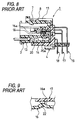
- Figs. 6 to 8 show a conventional half-fitting detection connector provided with a connection detection device for checking whether or not male and female connectors are completely fitted together.
- This half-fitting detection connector 1 is disclosed in Unexamined Japanese Patent Publication No. Hei. 7-142122.
- a lock projection 8 on an elastic lock arm 7, formed on a housing 13 of the male connector 3 is engaged in a retaining hole 11 in a housing 14 of the female connector 4, so that the pair of housings 13 and 14 are locked together in a connected condition, and also connection detection contacts (contact elements) 16 and 17, held respectively in predetermined corresponding positions in the male and female connectors 3 and 4, contact each other simultaneously when the engagement of the lock arm 7 is completed.
- the male and female connectors 3 and 4 are multi-pole connectors each having a plurality of connection terminals received and retained therein at predetermined intervals.
- One of the plurality of connection terminals, retained in the housing 13, serves as the connection detection contact 16 whereas one of the plurality of connection terminals, retained in the housing 14, serves as the connection detection contact 17.
- a resilient contact piece portion 16a of the connection detection contact 16 in the male connector 3 is connected at one end to the lock arm 7, and this contact piece portion 16a is displaced in accordance with the flexing (elastic deformation) of the lock arm 7.
- the lock arm 7 on the male connector 3 is flexed (elastically deformed) toward the housing 13 as shown in Fig. 7 until the amount of fitting of the two connectors relative to each other reaches a predetermined amount.
- the connection detection contacts 16 and 17 are kept out of contact with each other as shown in the drawings.
- connection detection terminal 17 and the connection terminals 18 and 19, provided at the female connector 4 are plate-like tab terminals.
- connection detection contact 16 has the leaf spring-like, resilient contact piece portion 16a which is displaced in a direction of the thickness thereof in accordance with the flexing of the lock arm 7, and is pressed against the surface of the connection detection contact 17.
- connection detection contacts 16 and 17 fail to be electrically connected together. Accordingly, since the detection electric circuit detects a non-electrically-connected condition, there is a possibility of erroneously judging the two connectors to be in a half-fitted condition.
- connection detection device comprising the connection detection contacts 16 and 17
- the reliability of the connection detection device is lowered, for example, by the intrusion of a foreign matter.
- connection detection contacts mounted respectively in predetermined positions
- a half-fitting detection connector which comprises a first connector housing including a fitting port formed therein, a first connection-detection terminal receivable in the first connector housing, a second connector housing fittable to the first connector housing, the second connector housing including an engagement portion, a second connection-detection terminal receivable in the second connector housing, and fittable to the first connection-detection terminal, the second connection-detection terminal including a spring portion which can be compressively deformed along a terminal fitting direction, a lock arm formed on the first connector housing, and substantially extending in a fitting direction of the first and second connector housings, the lock arm including a retaining projection, the lock arm retaining the first and second connector housings in a fitted condition when the retaining projection is engaged with the engagement portion of the second connector housing, and a screen plate formed on a distal end of the lock arm, the screen plate closing the fitting port of the first connector housing when the retaining projection is
- the half-fitting detection connector further comprises a third connection terminal receivable in the first connector housing, and a fourth connection terminal receivable in the second connector housing, and fittable to the third connection terminal, wherein a complete fitting between the third and fourth connection terminals is prevented when a fitting between the first and the second connection-detection terminals through the fitting port is obstructed by the screen plate.
- a half-fitted condition of the first and second connector housings is detected by a condition of electrical connection between the first connection-detection terminal and the second connection-detection terminal.
- the spring portion is formed integrally with the second connection-detection terminal.
- the second connection-detection terminal includes a contact portion for connecting with the first connection-detection terminal, and a wire clamping portion for clamping a wire, and wherein the spring portion is formed between the contact portion and the wire clamping portion.
- the lock arm is formed in a cantilever-like manner on an outer surface of the first connector housing to extend obliquely upwardly from the outer surface of the first connector housing in a natural condition in which no external force acts on the lock arm, so that the screen plate opens the fitting port of the first connector housing.
- the retaining projection of the lock arm abuts against an inner surface of the second connector housing so that the lock arm is downwardly urged toward the outer surface of the first connector housing thereby closing the fitting port with the screen plate, and the second connection-detection terminal is abutted against the screen plate, and when the first and second connector housings are in a completely-fitted condition, the retaining projection is engaged with the engagement portion formed in the inner surface of the second connector housing so that the screen plate opens the fitting port to allow the first connection-detection terminal to fit to the second connection-detection terminal through the fitting port.
- the spring portion of the second connection-detection terminal is compressively deformed along the terminal fitting direction, and the first and second connector housings are pushed back away from each other by a resilient force of the spring portion.
- the retaining projection of the lock arm is not engaged in the engagement portion of the second connector housing, and is urged by the inner surface of the second connector housing, and therefore the fitting port is closed by the screen plate formed on the distal end of the lock arm.
- the second connection-detection terminal, received in the second connector housing can not enter the fitting port in the first connector housing, so that the spring portion is compressively deformed along the terminal fitting direction, with its distal end held against the screen plate. Therefore, the first connection-detection terminal and the second connection-detection terminal, received and held in their respective connector housings, are positively kept out of contact with each other.
- a detection electric circuit detects a non-electrically-connected condition of the first and second connection-detection terminals, and therefore a half-fitted condition of the two connector housings can be positively detected.
- the distal end portion of the second connection-detection terminal, received in the second connector housing projects through the fitting port in the first connector housing by the resilient force of the spring portion, so that the second connection-detection terminal is positively fittingly connected to the first connection-detection terminal received in the first connector housing. Therefore, this electrical connection between the first and second connection-detection terminals is detected, thus positively detecting the completely-fitted condition of the two connector housings.
- the contact of the first and second connection-detection terminals with each other is achieved by the fitting operation effected along the connector fitting direction, and therefore even if a foreign matter is deposited on the surface of the first and second connection-detection terminals, this foreign matter is removed from the surface as a result of sliding movement between the first and second connection-detection terminals, and therefore the foreign matter will not be held between the two connection-detection terminals.
- the first connection-detection terminal and the second connection-detection terminal will not fail to properly contact with each other because of the intrusion of a foreign matter, and the fitted condition of the two connector housings can be accurately detected, and therefore the reliability of detection of a half-fitted condition can be enhanced.
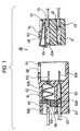
- Fig. 1 is an exploded, vertical cross-sectional view roughly showing one preferred embodiment of the half-fitting detection connector of the present invention
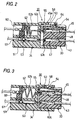
- Fig. 2 is a vertical cross-sectional view of the half-fitting detection connector of Fig. 1 in a half-fitted condition
- Fig. 3 is a vertical cross-sectional view of the half-fitting detection connector of Fig. 1 in a completely-fitted condition.
- the half-fitting detection connector 30 of this embodiment is a multi-pole connector comprising a pair of male and female connectors 33 and 34 to be fitted together in a male-female manner.
- Plural rows of juxtaposed terminal receiving chambers 45 are formed in a housing 43 of the male connector (first connector) 33, and extend therethrough in a direction of fitting of the two connectors, and female terminals 47 are received and held respectively in the associated terminal receiving chambers 45.
- a female connection-detection terminal 48 identical in construction to the female terminal 47, is received and held in one of the terminal receiving chambers 45.
- This female connection-detection terminal 48 cooperates with a male connection-detection terminal 62 (described later) to provide a connection detection device for detecting a half-fitted condition of the two connectors.
- Each of the female terminals 47, as well as the female connection-detection terminal 48, is retained in the associated terminal receiving chamber 45 against withdrawal by a retaining lance (not shown) or the like.
- a lock arm 53 is formed (molded) integrally on an outer surface (upper surface in Fig. 1) of the housing 43, and extends in the direction of fitting of the male connector into the female connector (second connector) 34.
- the lock arm 53 is an elastic arm of the cantilever type extending from a rear end portion of the housing 43 toward a front end thereof.
- a retaining projection 54 formed on an upper surface of this lock arm, is engaged in an engagement hole 58 in the female connector 34 (described later), thereby locking the two connectors to each other in a fitted condition.
- a shutter 55 in the form of a screen plate is formed integrally at a distal end of the lock arm 53.
- the lock arm 53 When the lock arm 53 is in a natural condition in which no external force acts on the lock arm, the lock arm 53 extends obliquely upwardly in such a manner that the shutter 55, extending downwardly from the distal end of the lock arm 53, opens a fitting port 45a at a front end of the terminal receiving chamber 45 receiving the female connection-detection terminal 48, as shown in Fig. 1.
- the shutter 55 closes the fitting port 45a at the front end of the terminal receiving chamber 45 receiving the female connection-detection terminal 48.
- the shutter 55 is formed (molded) integrally at the distal end of the lock arm 53, the shutter may be molded into a separate member, in which case this separate member is connected to the lock arm to provide a unitary construction.
- Another alternative is to provide an integrally-molded structure in which the proximal end portion of the lock arm 53 is formed into a thin hinge portion, and the lock arm 53 extends perpendicularly from the upper surface of the housing 43, and in use, the lock arm 53 thus molded is tilted toward the front end portion of the housing 43.
- Terminal receiving chambers 60 and 61 are formed longitudinally through a housing 51 of the female connector 34, and are arranged in corresponding relation to the terminal receiving chambers 45 in the male connector 33.
- Male terminals 63 to be received in the second connector are received and held respectively in the terminal receiving chambers 61 corresponding respectively to the terminal receiving chambers 45 receiving the female terminals 47, respectively.
- the male connection-detection terminal 62 to be received in the second connector is received and held in the terminal receiving chamber 60 corresponding to the terminal receiving chamber 45 receiving the female connection-detection terminal 48.
- the engagement hole 58 is formed in a connector fitting portion of the housing 51 defined by a front portion thereof, and when the male connector 33 is completely fitted in the female connector 34, the retaining projection 54 is fitted in the engagement hole 58, thereby locking the two connectors to each other in this completely-fitted condition.
- This engagement portion is not limited to the engagement hole 58, but may be a step portion or the like recessed in the inner surface of the connector fitting portion.
- the male connection-detection terminal 62 of an integral construction includes a wire clamping portion 62a for clamping connection to an end portion of a wire, a spring portion 62b formed into a wavy shape, and a tongue-like portion 62c for fitting into the female connection-detection terminal 48.
- the spring portion 62b can be compressively deformed along a terminal fitting direction.
- the male connection-detection terminal 62 is fixed to the housing 51 at that portion thereof disposed adjacent to the wire clamping portion 62a, and the wavy spring portion 62b is resiliently deformed in the direction of compression thereof in accordance with the amount of a pressing force applied to the tongue-like portion 62c defining the distal end portion of this male terminal.
- the male connection-detection terminal 62 is inserted into the terminal receiving chamber 60, and thereafter terminal holders 65 and 66 are inserted into the housing 51 to hold the male connection-detection terminal 62 therebetween to thereby retain the same in a predetermined position in the terminal receiving chamber 60.
- the male terminals 63 corresponding respectively to the female terminals 47 received in the male connector 33, are of the ordinary type, and each of these male terminals 63 has an integral construction, and includes a wire clamping portion 63a for clamping connection to an end portion of a wire, and a tongue-like portion 63c for fitting into the female terminal 47.
- the retaining projection 54 formed on the lock arm 53 of the male connector 33, abuts against an inner surface 64 of the housing 51, lying between the engagement hole 58 in the housing 51 and the front end of the housing 51, so that the lock arm 53 is urged or pressed toward the terminal receiving chambers 45 to be disposed generally parallel to the upper surface of the housing 43.
- the male connector 33 is inserted into the connector fitting portion of the female connector 34, with the shutter 55 closing the fitting port 45a of the terminal receiving chamber 45 receiving the female connection-detection terminal 48.
- the male connection-detection terminal 62 received in the female connector 34, can not enter the fitting port 45a of the terminal receiving chamber 45, receiving the female connection-detection terminal 48, so that the spring portion 62b is compressively deformed along the terminal fitting direction, with the tongue-like portion 62c held against the shutter 55. Therefore, the female connection-detection terminal 48 and the male connection-detection terminal 62, received and held respectively in the male and female connectors 33 and 34, are positively kept out of contact with each other.
- a detection electric circuit (not shown) detects a non-electrically-connected condition of the female and male connection-detection terminals 48 and 62, and therefore a half-fitted condition of the two connectors can be positively detected.
- the detection electric circuit detects this electrical connection between the female and male connection-detection terminals 48 and 62, thus positively detecting the completely-fitted condition of the two connectors.
- the contact of the female and male connection-detection terminals 48 and 62 with each other is achieved by the fitting operation effected along the connector fitting direction, and therefore even if a foreign matter is deposited on the surface of the female connection-detection terminal 48 or the surface of the male connection-detection terminal 62, this foreign matter is removed from the surface as a result of sliding movement between the two terminals 48 and 62, and therefore the foreign matter will not be held between the two terminals 48 and 62.
- the female connection-detection terminal 48 and the male connection-detection terminal 62 will not fail to properly contact with each other because of the intrusion of a foreign matter, and the fitted condition of the two connectors can be accurately detected, and therefore the reliability of detection of a half-fitted condition can be enhanced.
- the housings, the lock arm, the screen plate, the spring portion and so on are not limited to their respective structures in the half-fitting detection connector 30 of this embodiment, but can be modified in various ways without departing from the scope of the present invention.
- a male connection-detection terminal 68 shown in Figs. 4A and 4B, is a male connection-detection terminal to be received in the second connector, and this male connection-detection terminal of an integral construction includes a wire clamping portion 68a for clamping connection to the end portion of the wire, a spring portion 68b, and a tongue-like portion 68c for fitting into the female connection-detection terminal 48.
- the spring portion 68b is in the form of a volute spring (a conical coil spring having a rectangular cross-section) which can be compressively deformed along the terminal fitting direction.
- the spring portion 68b is resiliently deformed in the direction of compression thereof in accordance with the amount of a pressing force applied to the tongue-like portion 68c defining the distal end portion of the male connection-detection terminal.
- a male connection-detection terminal 70 shown in Fig. 5, is a male connection-detection terminal to be received in the second connector, and this male connection-detection terminal of an integral construction includes a wire clamping portion 70a for clamping connection to the end portion of the wire, a spring portion 70b, and a tongue-like portion 70c for fitting into the female connection-detection terminal 48.
- the spring portion 70b is in the form of a compression coil spring which can be compressively deformed along the terminal fitting direction.
- the spring portion 70b is resiliently deformed in the direction of compression thereof in accordance with the amount of a pressing force applied to the tongue-like portion 70c defining the distal end portion of the male connection-detection terminal.
- the spring portion of the male connection-detection terminal, received in the second connector can be compressed in the predetermined amount in a half-fitted condition of the two connectors, and can also provide the predetermined resilient force necessary for connecting the male connection-detection terminal to the female connection-detection terminal, received in the first connector, in the connector fitting operation
- the spring portion which can be compressively deformed along the terminal fitting direction, can have any suitable structure, and is not limited to the structure in the above embodiment, and can take any suitable form.
- the male connection-detection terminal-fitting port in the first connector is closed by the screen plate formed at the distal end of the lock arm. Therefore, the male connection-detection terminal, received in the second connector, can not enter the fitting port for the female connection-detection terminal in the first connector, so that the spring portion is compressively deformed along the terminal fitting direction, with its distal end held against the screen plate. Therefore, the female connection-detection terminal and the male connection-detection terminal are positively kept out of contact with each other.
- the detection electric circuit detects a non-electrically-connected condition of the female and male connection-detection terminals, and therefore a half-fitted condition of the two connectors can be positively detected.
- the distal end portion of the male connection-detection terminal, received in the second connector projects through the fitting port in the first connector by the resilient force of the spring portion, so that the male connection-detection terminal is positively fittingly connected to the female connection-detection terminal received in the first connector. Therefore, this electrical connection between the female and male connection-detection terminals is detected, thus positively detecting the completely-fitted condition of the two connectors.
- the contact of the female and male connection-detection terminals with each other is achieved by the fitting operation effected along the connector fitting direction, and therefore even if a foreign matter is deposited on the surface of the terminals, this foreign matter is removed from the surface as a result of sliding movement between the female and male connection-detection terminals, and therefore the foreign matter will not be held between the two terminals.
- the female connection-detection terminal and the male connection-detection terminal will not fail to properly contact with each other because of the intrusion of a foreign matter, and the fitted condition of the two connectors can be accurately detected, and therefore the reliability of detection of a half-fitted condition can be enhanced.
Landscapes
- Details Of Connecting Devices For Male And Female Coupling (AREA)
Abstract
Description
Claims (10)
- A half-fitting detection connector, comprising:a first connector housing including a fitting port formed therein;a first connection-detection terminal receivable in the first connector housing;a second connector housing fittable to the first connector housing, the second connector housing including an engagement portion;a second connection-detection terminal receivable in the second connector housing, and fittable to the first connection-detection terminal, the second connection-detection terminal including a spring portion which can be compressively deformed along a terminal fitting direction;a lock arm formed on the first connector housing, and substantially extending in a fitting direction of the first and second connector housings, the lock arm including a retaining projection, the lock arm retaining the first and second connector housings in a fitted condition when the retaining projection is engaged with the engagement portion of the second connector housing; anda screen plate formed on a distal end of the lock arm, the screen plate closing the fitting port of the first connector housing when the retaining projection is urged by the second connector housing, and opening the fitting port to allow the first connection-detection terminal to fit to the second connection-detection terminal through the fitting port when the retaining projection is engaged with the engagement portion.
- A half-fitting detection connector according to claim 1, further comprising:a third connection terminal receivable in the first connector housing; anda fourth connection terminal receivable in the second connector housing, and fittable to the third connection terminal,
wherein a complete fitting between the third and fourth connection terminals is prevented when a fitting between the first and the second connection-detection terminals through the fitting port is obstructed by the screen plate. - A half-fitting detection connector according to claim 1, wherein a half-fitted condition of the first and second connector housings is detected by a condition of electrical connection between the first connection-detection terminal and the second connection-detection terminal.
- A half-fitting detection connector according to claim 1, wherein the spring portion is formed integrally with the second connection-detection terminal.
- A half-fitting detection connector according to claim 1, wherein the second connection-detection terminal includes a contact portion for connecting with the first connection-detection terminal, and a wire clamping portion for clamping a wire, and wherein the spring portion is formed between the contact portion and the wire clamping portion.
- A half-fitting detection connector according to claim 1, wherein the lock arm is formed in a cantilever-like manner on an outer surface of the first connector housing to extend obliquely upwardly from the outer surface of the first connector housing in a natural condition in which no external force acts on the lock arm, so that the screen plate opens the fitting port of the first connector housing.
- A half-fitting detection connector according to claim 6, wherein, when the first and second connector housings are in a half-fitted condition, the retaining projection of the lock arm abuts against an inner surface of the second connector housing so that the lock arm is downwardly urged toward the outer surface of the first connector housing thereby closing the fitting port with the screen plate, and the second connection-detection terminal is abutted against the screen plate, and when the first and second connector housings are in a completely-fitted condition, the retaining projection is engaged with the engagement portion formed in the inner surface of the second connector housing so that the screen plate opens the fitting port to allow the first connection-detection terminal to fit to the second connection-detection terminal through the fitting port.
- A half-fitting detection connector according to claim 7, wherein when the first and second connector housings are in a half-fitted condition, the spring portion of the second connection-detection terminal is compressively deformed along the terminal fitting direction, and the first and second connector housings are pushed back away from each other by a resilient force of the spring portion.
- A half-fitting detection connector according to claim 1, wherein, when the first and second connector housings are in a half-fitted condition, the retaining projection of the lock arm abuts against an inner surface of the second connector housing so that the screen plate closes the fitting port, and the second connection-detection terminal is abutted against the screen plate, and when the first and second connector housings are in a completely-fitted condition, the retaining projection is engaged with the engagement portion formed in the inner surface of the second connector housing so that the screen plate opens the fitting port to allow the first connection-detection terminal to fit to the second connection-detection terminal through the fitting port.
- A half-fitting detection connector according to claim 9, wherein when the first and second connector housings are in a half-fitted condition, the spring portion of the second connection-detection terminal is compressively deformed along the terminal fitting direction, and the first and second connector housings are pushed back away from each other by a resilient force of the spring portion.
Applications Claiming Priority (2)
| Application Number | Priority Date | Filing Date | Title |
|---|---|---|---|
| JP18203799 | 1999-06-28 | ||
| JP11182037A JP2001015213A (en) | 1999-06-28 | 1999-06-28 | Half mating detection connector |
Publications (3)
| Publication Number | Publication Date |
|---|---|
| EP1065757A2 true EP1065757A2 (en) | 2001-01-03 |
| EP1065757A3 EP1065757A3 (en) | 2002-02-27 |
| EP1065757B1 EP1065757B1 (en) | 2005-11-30 |
Family
ID=16111243
Family Applications (1)
| Application Number | Title | Priority Date | Filing Date |
|---|---|---|---|
| EP00304670A Expired - Lifetime EP1065757B1 (en) | 1999-06-28 | 2000-06-01 | Half-fitting detection connector |
Country Status (4)
| Country | Link |
|---|---|
| US (1) | US6254424B1 (en) |
| EP (1) | EP1065757B1 (en) |
| JP (1) | JP2001015213A (en) |
| DE (1) | DE60024359T2 (en) |
Cited By (2)
| Publication number | Priority date | Publication date | Assignee | Title |
|---|---|---|---|---|
| WO2013021624A1 (en) * | 2011-08-08 | 2013-02-14 | Yazaki Corporation | Connector |
| EP3624276A4 (en) * | 2017-05-09 | 2021-01-13 | Iriso Electronics Co., Ltd. | CONNECTOR |
Families Citing this family (11)
| Publication number | Priority date | Publication date | Assignee | Title |
|---|---|---|---|---|
| JP2001345147A (en) * | 2000-05-31 | 2001-12-14 | Yazaki Corp | Half mating prevention connector |
| JP2001351738A (en) * | 2000-06-06 | 2001-12-21 | Yazaki Corp | Half mating prevention connector |
| KR100463180B1 (en) * | 2002-05-24 | 2004-12-23 | 삼성에스디아이 주식회사 | Electric Connector Assembly |
| JP4075543B2 (en) * | 2002-09-11 | 2008-04-16 | 市光工業株式会社 | Mirror drive device |
| JP4444289B2 (en) * | 2004-07-09 | 2010-03-31 | 株式会社村上開明堂 | Mirror surface adjustment actuator and manufacturing method thereof |
| US7214086B1 (en) * | 2006-03-06 | 2007-05-08 | Yu-Chu Hsieh | Large current connector |
| TW200926539A (en) * | 2007-12-14 | 2009-06-16 | Asustek Comp Inc | Portable electronic apparatus, power detection terminal and power detection method |
| JP2009199859A (en) * | 2008-02-21 | 2009-09-03 | Elpida Memory Inc | Wiping socket |
| JP5528853B2 (en) * | 2010-03-04 | 2014-06-25 | 本田技研工業株式会社 | Valve body mounting structure |
| DE102010037498B4 (en) | 2010-09-13 | 2013-11-07 | Hachadorian Design & Calculation Gmbh | Electric contact |
| JP6899268B2 (en) * | 2017-07-05 | 2021-07-07 | 矢崎エナジーシステム株式会社 | Semi-fitting prevention connector |
Family Cites Families (6)
| Publication number | Priority date | Publication date | Assignee | Title |
|---|---|---|---|---|
| JP2573753B2 (en) * | 1991-04-01 | 1997-01-22 | 矢崎総業株式会社 | connector |
| JP2725759B2 (en) | 1993-11-18 | 1998-03-11 | 矢崎総業株式会社 | Connector coupling detection device and short-circuit contact |
| JP3247031B2 (en) * | 1995-06-16 | 2002-01-15 | 矢崎総業株式会社 | Connector tester |
| JP3159053B2 (en) * | 1996-05-31 | 2001-04-23 | 住友電装株式会社 | connector |
| JP3327178B2 (en) * | 1997-08-26 | 2002-09-24 | 住友電装株式会社 | connector |
| BR9803554A (en) * | 1997-09-09 | 1999-11-16 | Sumitomo Wiring Systems | Connector |
-
1999
- 1999-06-28 JP JP11182037A patent/JP2001015213A/en active Pending
-
2000
- 2000-06-01 DE DE60024359T patent/DE60024359T2/en not_active Expired - Fee Related
- 2000-06-01 EP EP00304670A patent/EP1065757B1/en not_active Expired - Lifetime
- 2000-06-21 US US09/598,514 patent/US6254424B1/en not_active Expired - Fee Related
Cited By (3)
| Publication number | Priority date | Publication date | Assignee | Title |
|---|---|---|---|---|
| WO2013021624A1 (en) * | 2011-08-08 | 2013-02-14 | Yazaki Corporation | Connector |
| US9112297B2 (en) | 2011-08-08 | 2015-08-18 | Yazaki Corporation | Connector having terminal accommodating chambers |
| EP3624276A4 (en) * | 2017-05-09 | 2021-01-13 | Iriso Electronics Co., Ltd. | CONNECTOR |
Also Published As
| Publication number | Publication date |
|---|---|
| US6254424B1 (en) | 2001-07-03 |
| DE60024359T2 (en) | 2006-06-08 |
| EP1065757B1 (en) | 2005-11-30 |
| EP1065757A3 (en) | 2002-02-27 |
| DE60024359D1 (en) | 2006-01-05 |
| JP2001015213A (en) | 2001-01-19 |
Similar Documents
| Publication | Publication Date | Title |
|---|---|---|
| US7556539B2 (en) | Connector | |
| US5562486A (en) | Lock detection connector | |
| US6638109B2 (en) | Connector with a side retainer | |
| US6705881B2 (en) | Lever-type connector | |
| EP1065757B1 (en) | Half-fitting detection connector | |
| US6439914B2 (en) | Connector having a short-circuiting element | |
| EP3751675B1 (en) | Housing comprising an engaging piece inserted into a seal mounting portion and abutting said seal mounting portion | |
| US6171124B1 (en) | Connector | |
| EP1570548B1 (en) | Electrical connector with terminal position assurance system | |
| JP2001155810A (en) | connector | |
| US5910028A (en) | Connector | |
| EP1077513B1 (en) | A terminal fitting, a connector housing and a connector comprising the same | |
| EP1801931B1 (en) | A connector and a method for controlling the assembly thereof | |
| US6250945B1 (en) | Half-fitting prevention connector | |
| EP0836251A2 (en) | Electrical connector with shunt | |
| EP0871253B1 (en) | Lock detection connector | |
| JPH09306582A (en) | Connector | |
| US6551146B2 (en) | Connector and a method for assembling a connector | |
| US6416345B1 (en) | Connector lock mechanism with elastic arm portion | |
| JPH04118877A (en) | Connection confirming device for connector | |
| JPH08148215A (en) | Locking structure of short-circuiting contact in connector | |
| EP0967686B1 (en) | Electrical connector with terminal position assurance device | |
| JP3666087B2 (en) | Connector with half-mating detection function | |
| JP3284200B2 (en) | Electrical connector assembly | |
| JPH11167949A (en) | Connector |
Legal Events
| Date | Code | Title | Description |
|---|---|---|---|
| PUAI | Public reference made under article 153(3) epc to a published international application that has entered the european phase |
Free format text: ORIGINAL CODE: 0009012 |
|
| AK | Designated contracting states |
Kind code of ref document: A2 Designated state(s): AT BE CH CY DE DK ES FI FR GB GR IE IT LI LU MC NL PT SE Kind code of ref document: A2 Designated state(s): DE FR GB |
|
| AX | Request for extension of the european patent |
Free format text: AL;LT;LV;MK;RO;SI |
|
| PUAL | Search report despatched |
Free format text: ORIGINAL CODE: 0009013 |
|
| AK | Designated contracting states |
Kind code of ref document: A3 Designated state(s): AT BE CH CY DE DK ES FI FR GB GR IE IT LI LU MC NL PT SE |
|
| AX | Request for extension of the european patent |
Free format text: AL;LT;LV;MK;RO;SI |
|
| RIC1 | Information provided on ipc code assigned before grant |
Free format text: 7H 01R 13/629 A, 7H 01R 13/627 B |
|
| 17P | Request for examination filed |
Effective date: 20020806 |
|
| AKX | Designation fees paid |
Free format text: DE FR GB |
|
| GRAP | Despatch of communication of intention to grant a patent |
Free format text: ORIGINAL CODE: EPIDOSNIGR1 |
|
| GRAS | Grant fee paid |
Free format text: ORIGINAL CODE: EPIDOSNIGR3 |
|
| GRAA | (expected) grant |
Free format text: ORIGINAL CODE: 0009210 |
|
| AK | Designated contracting states |
Kind code of ref document: B1 Designated state(s): DE FR GB |
|
| REG | Reference to a national code |
Ref country code: GB Ref legal event code: FG4D |
|
| REF | Corresponds to: |
Ref document number: 60024359 Country of ref document: DE Date of ref document: 20060105 Kind code of ref document: P |
|
| PGFP | Annual fee paid to national office [announced via postgrant information from national office to epo] |
Ref country code: DE Payment date: 20060525 Year of fee payment: 7 |
|
| PG25 | Lapsed in a contracting state [announced via postgrant information from national office to epo] |
Ref country code: GB Free format text: LAPSE BECAUSE OF NON-PAYMENT OF DUE FEES Effective date: 20060601 |
|
| PGFP | Annual fee paid to national office [announced via postgrant information from national office to epo] |
Ref country code: FR Payment date: 20060608 Year of fee payment: 7 |
|
| ET | Fr: translation filed | ||
| PLBE | No opposition filed within time limit |
Free format text: ORIGINAL CODE: 0009261 |
|
| STAA | Information on the status of an ep patent application or granted ep patent |
Free format text: STATUS: NO OPPOSITION FILED WITHIN TIME LIMIT |
|
| 26N | No opposition filed |
Effective date: 20060831 |
|
| GBPC | Gb: european patent ceased through non-payment of renewal fee |
Effective date: 20060601 |
|
| REG | Reference to a national code |
Ref country code: FR Ref legal event code: ST Effective date: 20080229 |
|
| PG25 | Lapsed in a contracting state [announced via postgrant information from national office to epo] |
Ref country code: DE Free format text: LAPSE BECAUSE OF NON-PAYMENT OF DUE FEES Effective date: 20080101 |
|
| PG25 | Lapsed in a contracting state [announced via postgrant information from national office to epo] |
Ref country code: FR Free format text: LAPSE BECAUSE OF NON-PAYMENT OF DUE FEES Effective date: 20070702 |