EP1065688A2 - Sheet with movable contacts and sheet switch - Google Patents
Sheet with movable contacts and sheet switch Download PDFInfo
- Publication number
- EP1065688A2 EP1065688A2 EP00113672A EP00113672A EP1065688A2 EP 1065688 A2 EP1065688 A2 EP 1065688A2 EP 00113672 A EP00113672 A EP 00113672A EP 00113672 A EP00113672 A EP 00113672A EP 1065688 A2 EP1065688 A2 EP 1065688A2
- Authority
- EP
- European Patent Office
- Prior art keywords
- sheet
- movable contacts
- adhesive
- affixed
- holes
- Prior art date
- Legal status (The legal status is an assumption and is not a legal conclusion. Google has not performed a legal analysis and makes no representation as to the accuracy of the status listed.)
- Withdrawn
Links
- 239000000853 adhesive Substances 0.000 claims abstract description 45
- 230000001070 adhesive effect Effects 0.000 claims abstract description 45
- 230000001681 protective effect Effects 0.000 claims description 5
- 230000000994 depressogenic effect Effects 0.000 description 13
- 239000000428 dust Substances 0.000 description 6
- 229920000139 polyethylene terephthalate Polymers 0.000 description 4
- 239000005020 polyethylene terephthalate Substances 0.000 description 4
- 230000000881 depressing effect Effects 0.000 description 3
- 239000011810 insulating material Substances 0.000 description 3
- 229920003002 synthetic resin Polymers 0.000 description 3
- 239000000057 synthetic resin Substances 0.000 description 3
- 238000005260 corrosion Methods 0.000 description 2
- 230000007797 corrosion Effects 0.000 description 2
- 239000007789 gas Substances 0.000 description 2
- -1 polyethylene terephthalate Polymers 0.000 description 2
- KXGFMDJXCMQABM-UHFFFAOYSA-N 2-methoxy-6-methylphenol Chemical compound [CH]OC1=CC=CC([CH])=C1O KXGFMDJXCMQABM-UHFFFAOYSA-N 0.000 description 1
- 229910000906 Bronze Inorganic materials 0.000 description 1
- OKTJSMMVPCPJKN-UHFFFAOYSA-N Carbon Chemical compound [C] OKTJSMMVPCPJKN-UHFFFAOYSA-N 0.000 description 1
- RYGMFSIKBFXOCR-UHFFFAOYSA-N Copper Chemical compound [Cu] RYGMFSIKBFXOCR-UHFFFAOYSA-N 0.000 description 1
- OAICVXFJPJFONN-UHFFFAOYSA-N Phosphorus Chemical compound [P] OAICVXFJPJFONN-UHFFFAOYSA-N 0.000 description 1
- 239000010974 bronze Substances 0.000 description 1
- 229910052799 carbon Inorganic materials 0.000 description 1
- 239000011889 copper foil Substances 0.000 description 1
- KUNSUQLRTQLHQQ-UHFFFAOYSA-N copper tin Chemical compound [Cu].[Sn] KUNSUQLRTQLHQQ-UHFFFAOYSA-N 0.000 description 1
- 238000005530 etching Methods 0.000 description 1
- 239000002184 metal Substances 0.000 description 1
- 229910052751 metal Inorganic materials 0.000 description 1
- 239000007769 metal material Substances 0.000 description 1
- 238000000034 method Methods 0.000 description 1
- 230000002093 peripheral effect Effects 0.000 description 1
- 229920001568 phenolic resin Polymers 0.000 description 1
- 239000005011 phenolic resin Substances 0.000 description 1
- 229910001220 stainless steel Inorganic materials 0.000 description 1
- 239000010935 stainless steel Substances 0.000 description 1
Images


Classifications
-
- H—ELECTRICITY
- H01—ELECTRIC ELEMENTS
- H01H—ELECTRIC SWITCHES; RELAYS; SELECTORS; EMERGENCY PROTECTIVE DEVICES
- H01H13/00—Switches having rectilinearly-movable operating part or parts adapted for pushing or pulling in one direction only, e.g. push-button switch
- H01H13/50—Switches having rectilinearly-movable operating part or parts adapted for pushing or pulling in one direction only, e.g. push-button switch having a single operating member
- H01H13/52—Switches having rectilinearly-movable operating part or parts adapted for pushing or pulling in one direction only, e.g. push-button switch having a single operating member the contact returning to its original state immediately upon removal of operating force, e.g. bell-push switch
-
- H—ELECTRICITY
- H01—ELECTRIC ELEMENTS
- H01H—ELECTRIC SWITCHES; RELAYS; SELECTORS; EMERGENCY PROTECTIVE DEVICES
- H01H13/00—Switches having rectilinearly-movable operating part or parts adapted for pushing or pulling in one direction only, e.g. push-button switch
- H01H13/70—Switches having rectilinearly-movable operating part or parts adapted for pushing or pulling in one direction only, e.g. push-button switch having a plurality of operating members associated with different sets of contacts, e.g. keyboard
- H01H13/7006—Switches having rectilinearly-movable operating part or parts adapted for pushing or pulling in one direction only, e.g. push-button switch having a plurality of operating members associated with different sets of contacts, e.g. keyboard comprising a separate movable contact element for each switch site, all other elements being integrated in layers
-
- H—ELECTRICITY
- H01—ELECTRIC ELEMENTS
- H01H—ELECTRIC SWITCHES; RELAYS; SELECTORS; EMERGENCY PROTECTIVE DEVICES
- H01H2205/00—Movable contacts
- H01H2205/016—Separate bridge contact
- H01H2205/024—Means to facilitate positioning
- H01H2205/026—Adhesive sheet
-
- H—ELECTRICITY
- H01—ELECTRIC ELEMENTS
- H01H—ELECTRIC SWITCHES; RELAYS; SELECTORS; EMERGENCY PROTECTIVE DEVICES
- H01H2213/00—Venting
- H01H2213/01—Venting with internal pressure of other switch sites
Definitions
- the present invention relates to a sheet with movable contacts and a sheet switch using the same, which are for use in operating panels of various electronic devices for example.
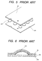
- FIG. 5 is an exploded perspective view of the sheet with movable contacts
- Fig. 6 is a sectional view thereof
- Fig. 7 is an exploded perspective view of the sheet switch
- Fig. 8 is a sectional view thereof.
- the sheet with movable contacts is made up of movable contacts 23 formed in a dome shape using metal, a sheet 21 formed by an insulating film, the sheet 21 covering upper surfaces of the movable contacts 23 and having an adhesive 22 applied to a lower surface thereof, and a separator sheet 24 affixed to the lower surface of the sheet 21 to close lower surfaces of the movable contacts 23, the separator sheet 24 being formed by paper or an insulating film.
- the domed upper surfaces of the movable contacts 23 are covered with and fixed to the adhesive 22 which is applied to the lower surface of the sheet 21.
- the separator sheet 24 affixed to the lower surface of the sheet 21 is for preventing corrosion of the movable contacts 23 caused by gases contained in air or for preventing the adhesion of foreign matters to the movable contacts, during storage or transport of the sheet.
- the separator 24 can be peeled off.
- the sheet switch is made up of the above sheet with movable contacts and a circuit board 28 provided on an upper surface thereof with central fixed contacts 30 and outer fixed contacts 29.
- the movable contacts 23 are affixed onto the circuit board 28 using the adhesive applied to the lower surface of the sheet 21 in such a manner that lower ends of outer peripheries of the movable contacts 23 are respectively brought into abutment with the outer fixed contacts 29 and that central portions thereof are opposed to the central fixed contacts 30.
- the movable contacts 23 are covered with and fixed to a single sheet 21 of an insulating film with the adhesive 22 applied to the lower surface of the sheet, so when the sheet with movable contacts is affixed onto the circuit board 28 and when any of the domed movable contacts 23 located near the outer periphery of the sheet 21 is depressed, the air present within the dome of the movable contact is forced out and causes an end portion of the sheet to float, thus giving rise to the problem that dust enters through the floating end portion and causes an incomplete state of contact.
- the portions of the sheet 21 which surround the domed movable contacts 23 are fixed with the adhesive 22, so when any of the movable contacts 23 is depressed, the air present within the dome of the depressed movable contact cannot escape anywhere, thus giving rise to the problem that the operation feeling is deteriorated.
- a sheet with movable contacts comprising a first sheet formed by an insulating film, the first sheet having an adhesive surface formed by applying an adhesive to a lower surface of the first sheet, a plurality of domed, metallic, movable contacts whose upper surfaces are covered with and affixed to the adhesive surface of the first sheet, and a second sheet formed by an insulating film, the second sheet being affixed to the lower surface of the first sheet and having a plurality of receptacle holes for receiving the movable contacts therein, with an adhesive being applied to a lower surface of the second sheet, wherein the second sheet has connecting slots formed therein for connecting adjacent such receptacle holes with each other.
- a separator sheet whose upper surface has been subjected to a release treatment is affixed to the lower surface of the second sheet so as to be releasable from the second sheet.
- through holes are formed in the separator sheet opposedly to the plural receptacle holes formed in the second sheet, and a protective sheet is affixed to a lower surface of the separator sheet to close the through holes.
- a sheet switch comprising the sheet with movable contacts first referred to above and a circuit board having a plurality of fixed contacts, wherein, with the movable contacts arranged opposedly to the fixed contacts, the sheet with movable contacts is affixed onto the circuit board with the adhesive applied to the lower surface of the second sheet.
- FIGS. 1 and 2 show a structure of a sheet with movable contacts embodying the present invention, of which Fig. 1 is a partially cut-away perspective view of the sheet and Fig. 2 is a sectional view of a movable contact portion.
- a first sheet 1 is formed by a film of an insulating material such as a synthetic resin, e.g. PET (polyethylene terephthalate), with an adhesive 2 being applied throughout a lower surface of the first sheet 1 to form an adhesive surface.
- an insulating material such as a synthetic resin, e.g. PET (polyethylene terephthalate)
- PET polyethylene terephthalate
- Movable contacts 3 are each formed in the shape of a dome having a central portion 3a with use of a resilient metallic material such as stainless steel or phosphor bronze.
- the central portion 3a is inverted to the opposite side when depressed with an external force.
- a second sheet 4 like the first sheet 1, is also formed by a film of an insulating material such as a synthetic resin, e.g. PET (polyethylene terephthalate). Also throughout a lower surface of the second sheet 4 is applied an adhesive 5 to form an adhesive surface.
- an adhesive 5 to form an adhesive surface.
- the second sheet 4 are formed a plurality of circular receptacle holes 4a for receiving the movable contacts 3 therein.
- the receptacle holes 4a are formed with connecting slots 4b for connecting adjacent receptacle holes 4a with each other.
- a separator sheet 6 is formed by a film of an insulating material such as paper or a synthetic resin. An upper surface of the separator sheet 6 has been subjected to a release treatment so as to be releasable from the adhesive surface formed on the second sheet 4 using the adhesive 5. As in the second sheet 4, a plurality of circular through holes 6a are formed in the separator sheet 6, with connecting slots 6b being formed in the through holes 6a for connecting adjacent through holes 6a with each other.
- a protective sheet 7 is formed by an insulating film having an adhesive upper surface and is affixed to a lower surface of the separator sheet 6 so as to close the plural through holes 6a.
- the sheet with movable contacts constructed as above is assembled in the following manner. First, the adhesive surface of the adhesive 5 applied to the lower surface of the second sheet 4 is registered with the upper surface of the separator sheet 6 and in this state the second sheet is affixed to the separator sheet upper surface. Next, in the thus-laminated sheets are formed the receptacle holes 4a, through holes 6a, and connecting slots 4b, 6b in plural positions as necessary. In this case, the receptacle holes 4a, through holes 6a, and connecting slots 4b, 6b formed in the second sheet 4 and separator sheet 6 are of the same shape because they are formed at a time using a single punch.
- the adhesive surface of the adhesive 2 applied to the lower surface of the first sheet 1 is registered with the upper surface of the second sheet 4 and in this state the first sheet is affixed to the second sheet upper surface.
- the movable contacts 3 are inserted through the plural through holes 6a from the underside of the separator sheet 6 and the domed upper surfaces thereof are affixed to the adhesive surface of the adhesive 2 applied to the lower surface of the first sheet 1. In this state the movable contacts are received respectively in the receptacle holes 4a of the second sheet 4.
- the adhesive upper surface of the protective sheet 7 is registered with and affixed to the lower surface of the separator sheet 6 to complete the assembly.
- the adhesive surfaces of the adhesives 2 and 5 applied to the first and second sheets 1, 4, respectively, are not exposed to the exterior when affixing the movable contacts 3 to the first sheet 1, so there is no fear of adhesion of dust or the like to the adhesive surfaces and thus the occurrence of an incomplete state of contact can be prevented.
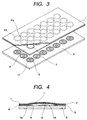
- Figs. 3 and 4 show a structure of a sheet switch using the sheet with movable contacts according to the present invention, of which Fig. 3 is a partially cut-away exploded perspective view of the sheet switch and Fig. 4 is a sectional view of a movable contact portion and a fixed contact portion.
- Figs. 1 and 2 the same components as in Figs. 1 and 2 are identified by the same reference numerals as in Figs. 1 and 2 and explanations thereof will here be omitted.
- a circuit board 8 is formed, for example, by an insulating laminate such as a phenolic resin laminate. On the circuit board 8 are formed a plurality of circuit patterns of outer fixed contacts 9 and central fixed contacts 10 by, for example, printing carbon or etching copper foil.
- the sheet switch is assembled in the following manner.
- the separator sheet 6 is peeled off from the sheet with movable contacts, for example, by pulling it with hands. Thereafter, the sheet with movable contacts is positioned onto the circuit board 8 and the movable contacts, whose upper surfaces are affixed to the first sheet 1 and which are received in the receptacle holes 4a, are affixed onto the circuit board 8 through the adhesive surface of the adhesive 5 applied to the lower surface of the second sheet 4 in such a manner that lower ends 3b of outer peripheries of the movable contacts 3 are abutted against the outer fixed contacts 9 and that the central portions 3a of the movable contacts are opposed to the central fixed contacts 10.
- the assembly is now over.
- a plurality of circular receptacle holes 4a for receiving the movable contacts 3 therein are formed in the second sheet 4 and connecting slots 4b for connecting adjacent receptacle holes 4a with each other are formed in the receptacle holes 4a, so when any of the movable contacts 3 is depressed through the first sheet 1, air 11 present in the dome of the movable contact 3 which is dome-shaped is conducted to the next receptacle hole 4a through the connecting slot 4b located therebetween.
- the second sheet having plural receptacle holes for receiving domed movable contacts therein is affixed to the lower surface of the first sheet and is formed with connecting slots for connecting adjacent receptacle holes with each other, the air present in the dome of each domed movable contact can pass through the associated connecting slot and escape to the next receptacle hole, thus ensuring an inverting motion of the movable contact within the receptacle hole and affording a good operation feeling.
- the separator sheet whose upper surface has been subjected to a release treatment is affixed to the lower surface of the second sheet so as to be releasable from the second sheet, so that the adhesive surfaces of adhesives applied to the first and second sheets are not exposed to the exterior when the movable contacts are affixed to the first sheet, so that there is no fear of adhesion of dust or the like to the adhesive surfaces and hence it is possible to prevent the occurrence of an incomplete state of contact.
- the sheet with movable contacts comprising the first sheet and the second sheet affixed to the lower surface of the first sheet and having plural receptacle holes for receiving domed movable contacts therein, with connecting slots for connecting adjacent receptacle holes with each other being formed in the second sheet, is affixed onto a circuit board having fixed contacts through the adhesive applied to the lower surface of the second sheet, the air present in the dome of each domed movable contact can escape into the next receptacle hole through the associated connecting slot and therefore the movable contact can surely be inverted within the associated receptacle hole, thus affording a good operation feeling. Additionally, also when any of the movable contacts located near the outer periphery of the sheet switch is depressed, it is possible to prevent floating of the sheet and hence possible to prevent the entry of dust.
Landscapes
- Push-Button Switches (AREA)
Abstract
Description
The
Claims (4)
- A sheet with movable contacts, comprising:a first sheet of an insulating film, the first sheet having an adhesive surface formed by applying an adhesive to a lower surface of the first sheet;a plurality of domed, metallic, movable contacts whose upper surfaces are covered with and affixed to the adhesive surface of the first sheet; anda second sheet formed by an insulating film, the second film being affixed to the lower surface of the first sheet and having a plurality of receptacle holes for receiving the movable contacts therein, with an adhesive being applied to a lower surface of the second sheet,
wherein the second sheet has connecting slots formed therein for connecting the adjacent receptacle holes with each other. - A sheet with movable contacts according to claim 1, wherein a separator sheet whose upper surface has been subjected to a release treatment is affixed to the lower surface of the second sheet so as to be releasable from the second sheet.
- A sheet with movable contacts according to claim 2, wherein through holes are formed in the separator sheet opposedly to the plural receptacle holes formed in the second sheet, and a protective sheet is affixed to a lower surface of the separator sheet to close the through holes.
- A sheet switch in which a sheet with movable contacts are affixed onto a circuit board provided with a plurality of fixed contacts such that the movable contacts are arranged oppositely to the fixed contacts,the sheet with movable contacts comprising:a first sheet of an insulating film, the first sheet having an adhesive surface formed by applying an adhesive to a lower surface of the first sheet;a plurality of domed, metallic, movable contacts whose upper surfaces are covered with and affixed to the adhesive surface of the first sheet; anda second sheet formed by an insulating film, the second film being affixed to the lower surface of the first sheet and having a plurality of receptacle holes for receiving the movable contacts and connecting slots for connecting the adjacent receptacle holes with each other, with an adhesive being applied to a lower surface of the second sheet.
Applications Claiming Priority (2)
| Application Number | Priority Date | Filing Date | Title |
|---|---|---|---|
| JP18323699 | 1999-06-29 | ||
| JP11183236A JP2001014973A (en) | 1999-06-29 | 1999-06-29 | Sheet with movable contact, and sheet switch |
Publications (2)
| Publication Number | Publication Date |
|---|---|
| EP1065688A2 true EP1065688A2 (en) | 2001-01-03 |
| EP1065688A3 EP1065688A3 (en) | 2002-05-08 |
Family
ID=16132168
Family Applications (1)
| Application Number | Title | Priority Date | Filing Date |
|---|---|---|---|
| EP00113672A Withdrawn EP1065688A3 (en) | 1999-06-29 | 2000-06-28 | Sheet with movable contacts and sheet switch |
Country Status (6)
| Country | Link |
|---|---|
| US (1) | US6417467B1 (en) |
| EP (1) | EP1065688A3 (en) |
| JP (1) | JP2001014973A (en) |
| KR (1) | KR100381941B1 (en) |
| CN (1) | CN1193392C (en) |
| TW (1) | TW503414B (en) |
Cited By (5)
| Publication number | Priority date | Publication date | Assignee | Title |
|---|---|---|---|---|
| WO2002103731A1 (en) * | 2001-06-15 | 2002-12-27 | Nokia Corporation | A switch arrangement |
| EP1239501A3 (en) * | 2001-03-08 | 2004-09-08 | Alps Electric Co., Ltd. | Easily peelable sheet having contact plates and switch device employing the same |
| EP1406276A4 (en) * | 2001-06-07 | 2005-03-09 | Fujikura Ltd | Metal dome sheet, its manufacturing method, and metal dome system |
| DE10236436B4 (en) * | 2001-08-08 | 2005-12-08 | Yazaki Corp. | switch |
| WO2006094868A1 (en) * | 2005-03-10 | 2006-09-14 | Siemens Aktiengesellschaft | Contact film keyboard |
Families Citing this family (10)
| Publication number | Priority date | Publication date | Assignee | Title |
|---|---|---|---|---|
| JP2003151393A (en) * | 2001-11-15 | 2003-05-23 | Matsushita Electric Ind Co Ltd | Movable contact body, panel switch using the same, and electronic device equipped with the panel switch |
| US7075025B2 (en) * | 2002-08-09 | 2006-07-11 | Fujikura Ltd. | Switch sheet and switch |
| KR100512374B1 (en) * | 2003-01-27 | 2005-09-05 | 삼성전자주식회사 | Key pattern connecting device for metal dome switch |
| JP4171713B2 (en) * | 2004-03-23 | 2008-10-29 | ホシデン株式会社 | Push-on switch |
| TWI286333B (en) * | 2004-03-26 | 2007-09-01 | Hon Hai Prec Ind Co Ltd | A dome sheet and a switch using the same |
| JP4612361B2 (en) * | 2004-08-31 | 2011-01-12 | ポリマテック株式会社 | Key switch |
| JP4317806B2 (en) * | 2004-10-19 | 2009-08-19 | アルプス電気株式会社 | Contact structure |
| JP2006216291A (en) * | 2005-02-02 | 2006-08-17 | Matsushita Electric Ind Co Ltd | Movable contact body and panel switch configured using the same |
| TWI417015B (en) * | 2008-09-19 | 2013-11-21 | Chi Mei Comm Systems Inc | Electronic device |
| USD809467S1 (en) | 2015-03-23 | 2018-02-06 | Citizen Electronics Co., Ltd. | Switch |
Family Cites Families (14)
| Publication number | Priority date | Publication date | Assignee | Title |
|---|---|---|---|---|
| US4375018A (en) * | 1980-06-16 | 1983-02-22 | Sheldahl, Inc. | Membrane switch having adhesive label as edge seal |
| US4367385A (en) * | 1981-01-26 | 1983-01-04 | W. H. Brady Co. | Capacitance switch |
| US4684767A (en) * | 1985-05-30 | 1987-08-04 | Phalen Robert F | Tactile affirmative response membrane switch |
| US4771139A (en) * | 1986-06-27 | 1988-09-13 | Desmet Gregory L | Keyboard with metal cover and improved switches |
| EP0322515A3 (en) * | 1987-12-30 | 1990-09-12 | Hewlett-Packard Company | Keyboard venting |
| JPH05234459A (en) * | 1991-03-19 | 1993-09-10 | Fujitsu Ltd | Membrane switch |
| JPH06176659A (en) * | 1992-12-07 | 1994-06-24 | Matsushita Electric Ind Co Ltd | Push button switch |
| US5399823A (en) * | 1993-11-10 | 1995-03-21 | Minimed Inc. | Membrane dome switch with tactile feel regulator shim |
| JPH0917278A (en) * | 1995-06-29 | 1997-01-17 | Idec Izumi Corp | Push button sheet of display operation panel |
| JP3988203B2 (en) * | 1996-10-22 | 2007-10-10 | 松下電器産業株式会社 | Movable contact for panel switch |
| JPH10125173A (en) * | 1996-10-23 | 1998-05-15 | Matsushita Electric Ind Co Ltd | Movable contact body for panel switch and panel switch using the same |
| JPH10233141A (en) * | 1997-02-18 | 1998-09-02 | Mitsumi Electric Co Ltd | Switch and its installation structure |
| US5845766A (en) | 1997-04-17 | 1998-12-08 | Matsushita Electric Industrial Co., Ltd. | Movable contact element for panel switch and method of manufacturing panel switch with movable contact element |
| JP3256471B2 (en) * | 1997-08-04 | 2002-02-12 | ホシデン株式会社 | Switch sheet for key switch unit, method of manufacturing the same, and key switch unit |
-
1999
- 1999-06-29 JP JP11183236A patent/JP2001014973A/en active Pending
-
2000
- 2000-05-29 TW TW089110404A patent/TW503414B/en not_active IP Right Cessation
- 2000-06-23 CN CNB001078283A patent/CN1193392C/en not_active Expired - Fee Related
- 2000-06-26 KR KR10-2000-0035363A patent/KR100381941B1/en not_active Expired - Fee Related
- 2000-06-27 US US09/604,223 patent/US6417467B1/en not_active Expired - Fee Related
- 2000-06-28 EP EP00113672A patent/EP1065688A3/en not_active Withdrawn
Cited By (7)
| Publication number | Priority date | Publication date | Assignee | Title |
|---|---|---|---|---|
| EP1239501A3 (en) * | 2001-03-08 | 2004-09-08 | Alps Electric Co., Ltd. | Easily peelable sheet having contact plates and switch device employing the same |
| EP1406276A4 (en) * | 2001-06-07 | 2005-03-09 | Fujikura Ltd | Metal dome sheet, its manufacturing method, and metal dome system |
| US6917007B2 (en) | 2001-06-07 | 2005-07-12 | Fujikura, Ltd. | Metal dome sheet, its manufacturing method, and metal dome system |
| WO2002103731A1 (en) * | 2001-06-15 | 2002-12-27 | Nokia Corporation | A switch arrangement |
| US7102086B2 (en) | 2001-06-15 | 2006-09-05 | Nokia Corporation | Switch arrangement |
| DE10236436B4 (en) * | 2001-08-08 | 2005-12-08 | Yazaki Corp. | switch |
| WO2006094868A1 (en) * | 2005-03-10 | 2006-09-14 | Siemens Aktiengesellschaft | Contact film keyboard |
Also Published As
| Publication number | Publication date |
|---|---|
| EP1065688A3 (en) | 2002-05-08 |
| JP2001014973A (en) | 2001-01-19 |
| CN1288245A (en) | 2001-03-21 |
| CN1193392C (en) | 2005-03-16 |
| US6417467B1 (en) | 2002-07-09 |
| TW503414B (en) | 2002-09-21 |
| KR20010021030A (en) | 2001-03-15 |
| KR100381941B1 (en) | 2003-05-01 |
Similar Documents
| Publication | Publication Date | Title |
|---|---|---|
| US6259046B1 (en) | Sheet with movable contacts and sheet switch | |
| KR100456825B1 (en) | A movable contact body for a panel switch | |
| US6417467B1 (en) | Sheet with movable contacts and sheet switch | |
| US6271491B1 (en) | Push button switch including dome-shaped movable contact having reverse function | |
| US3973091A (en) | Pushbutton keyboard assembly having pole and inner contacts simultaneously engaged by a bridging contact | |
| US6548779B2 (en) | Sheet having moving contacts and sheet switch | |
| US6664901B1 (en) | Keyboard input device | |
| US4289940A (en) | Keyboard switch covering pads | |
| US20100230267A1 (en) | Push switch | |
| JP2003124583A (en) | Flexible circuit board | |
| US7329823B2 (en) | Movable contact element and panel switch formed using the same | |
| US7075026B2 (en) | Movable contact body and panel switch using the same | |
| US20070170645A1 (en) | Sheet and sheet switch | |
| JP4279129B2 (en) | Sheet with movable contact and push button switch using the same | |
| GB1593414A (en) | Keyboard switch assemblies | |
| KR100384252B1 (en) | Movable contact and switch device using the same | |
| JP2009117222A (en) | Movable contact body and switch using the same | |
| JP4486012B2 (en) | Switch device | |
| JP2872304B2 (en) | Keyboard switch | |
| JP2002260486A (en) | Key switch structure of electric equipment | |
| JPH0721875A (en) | Push button switch | |
| JPH01186720A (en) | Push-button switch | |
| JP2007109674A (en) | Movable contact body for panel switch and panel switch using the same |
Legal Events
| Date | Code | Title | Description |
|---|---|---|---|
| PUAI | Public reference made under article 153(3) epc to a published international application that has entered the european phase |
Free format text: ORIGINAL CODE: 0009012 |
|
| AK | Designated contracting states |
Kind code of ref document: A2 Designated state(s): AT BE CH CY DE DK ES FI FR GB GR IE IT LI LU MC NL PT SE |
|
| AX | Request for extension of the european patent |
Free format text: AL;LT;LV;MK;RO;SI |
|
| PUAL | Search report despatched |
Free format text: ORIGINAL CODE: 0009013 |
|
| AK | Designated contracting states |
Kind code of ref document: A3 Designated state(s): AT BE CH CY DE DK ES FI FR GB GR IE IT LI LU MC NL PT SE |
|
| AX | Request for extension of the european patent |
Free format text: AL;LT;LV;MK;RO;SI |
|
| 17P | Request for examination filed |
Effective date: 20021010 |
|
| 17Q | First examination report despatched |
Effective date: 20021204 |
|
| AKX | Designation fees paid |
Designated state(s): DE FI FR GB |
|
| STAA | Information on the status of an ep patent application or granted ep patent |
Free format text: STATUS: THE APPLICATION IS DEEMED TO BE WITHDRAWN |
|
| 18D | Application deemed to be withdrawn |
Effective date: 20030415 |