EP1065369B1 - Improvements to a high-pressure pump for feeding fuel to an internal combustion engine - Google Patents
Improvements to a high-pressure pump for feeding fuel to an internal combustion engine Download PDFInfo
- Publication number
- EP1065369B1 EP1065369B1 EP00113949A EP00113949A EP1065369B1 EP 1065369 B1 EP1065369 B1 EP 1065369B1 EP 00113949 A EP00113949 A EP 00113949A EP 00113949 A EP00113949 A EP 00113949A EP 1065369 B1 EP1065369 B1 EP 1065369B1
- Authority
- EP
- European Patent Office
- Prior art keywords
- seal
- pressure pump
- cylinder
- head
- inlet
- Prior art date
- Legal status (The legal status is an assumption and is not a legal conclusion. Google has not performed a legal analysis and makes no representation as to the accuracy of the status listed.)
- Expired - Lifetime
Links
- 238000002485 combustion reaction Methods 0.000 title claims description 6
- 239000000446 fuel Substances 0.000 title claims description 5
- 230000013011 mating Effects 0.000 claims description 14
- 239000013536 elastomeric material Substances 0.000 claims description 4
- 238000007789 sealing Methods 0.000 description 2
- 230000004913 activation Effects 0.000 description 1
- 230000006835 compression Effects 0.000 description 1
- 238000007906 compression Methods 0.000 description 1
- 230000000694 effects Effects 0.000 description 1
- 230000001788 irregular Effects 0.000 description 1
- 230000003014 reinforcing effect Effects 0.000 description 1
Images

Classifications
-
- F—MECHANICAL ENGINEERING; LIGHTING; HEATING; WEAPONS; BLASTING
- F02—COMBUSTION ENGINES; HOT-GAS OR COMBUSTION-PRODUCT ENGINE PLANTS
- F02M—SUPPLYING COMBUSTION ENGINES IN GENERAL WITH COMBUSTIBLE MIXTURES OR CONSTITUENTS THEREOF
- F02M63/00—Other fuel-injection apparatus having pertinent characteristics not provided for in groups F02M39/00 - F02M57/00 or F02M67/00; Details, component parts, or accessories of fuel-injection apparatus, not provided for in, or of interest apart from, the apparatus of groups F02M39/00 - F02M61/00 or F02M67/00; Combination of fuel pump with other devices, e.g. lubricating oil pump
-
- F—MECHANICAL ENGINEERING; LIGHTING; HEATING; WEAPONS; BLASTING
- F02—COMBUSTION ENGINES; HOT-GAS OR COMBUSTION-PRODUCT ENGINE PLANTS
- F02M—SUPPLYING COMBUSTION ENGINES IN GENERAL WITH COMBUSTIBLE MIXTURES OR CONSTITUENTS THEREOF
- F02M63/00—Other fuel-injection apparatus having pertinent characteristics not provided for in groups F02M39/00 - F02M57/00 or F02M67/00; Details, component parts, or accessories of fuel-injection apparatus, not provided for in, or of interest apart from, the apparatus of groups F02M39/00 - F02M61/00 or F02M67/00; Combination of fuel pump with other devices, e.g. lubricating oil pump
- F02M63/02—Fuel-injection apparatus having several injectors fed by a common pumping element, or having several pumping elements feeding a common injector; Fuel-injection apparatus having provisions for cutting-out pumps, pumping elements, or injectors; Fuel-injection apparatus having provisions for variably interconnecting pumping elements and injectors alternatively
- F02M63/0225—Fuel-injection apparatus having a common rail feeding several injectors ; Means for varying pressure in common rails; Pumps feeding common rails
-
- F—MECHANICAL ENGINEERING; LIGHTING; HEATING; WEAPONS; BLASTING
- F02—COMBUSTION ENGINES; HOT-GAS OR COMBUSTION-PRODUCT ENGINE PLANTS
- F02M—SUPPLYING COMBUSTION ENGINES IN GENERAL WITH COMBUSTIBLE MIXTURES OR CONSTITUENTS THEREOF
- F02M59/00—Pumps specially adapted for fuel-injection and not provided for in groups F02M39/00 -F02M57/00, e.g. rotary cylinder-block type of pumps
- F02M59/44—Details, components parts, or accessories not provided for in, or of interest apart from, the apparatus of groups F02M59/02 - F02M59/42; Pumps having transducers, e.g. to measure displacement of pump rack or piston
-
- F—MECHANICAL ENGINEERING; LIGHTING; HEATING; WEAPONS; BLASTING
- F04—POSITIVE - DISPLACEMENT MACHINES FOR LIQUIDS; PUMPS FOR LIQUIDS OR ELASTIC FLUIDS
- F04B—POSITIVE-DISPLACEMENT MACHINES FOR LIQUIDS; PUMPS
- F04B1/00—Multi-cylinder machines or pumps characterised by number or arrangement of cylinders
- F04B1/04—Multi-cylinder machines or pumps characterised by number or arrangement of cylinders having cylinders in star- or fan-arrangement
- F04B1/0404—Details or component parts
-
- F—MECHANICAL ENGINEERING; LIGHTING; HEATING; WEAPONS; BLASTING
- F04—POSITIVE - DISPLACEMENT MACHINES FOR LIQUIDS; PUMPS FOR LIQUIDS OR ELASTIC FLUIDS
- F04B—POSITIVE-DISPLACEMENT MACHINES FOR LIQUIDS; PUMPS
- F04B53/00—Component parts, details or accessories not provided for in, or of interest apart from, groups F04B1/00 - F04B23/00 or F04B39/00 - F04B47/00
- F04B53/007—Cylinder heads
Definitions
- the present invention relates to improvements to a high-pressure pump for feeding fuel to an internal combustion engine, in particular a vehicle engine.
- High-pressure pumps of the above type normally comprise a body housing at least one cylinder in which a piston slides; and a head having a surface engaging a corresponding surface of the body to fix the cylinder.
- the head also has an intake conduit, the inlet of which is located at the head surface next to the cylinder seat.
- each cylinder is fixed by a corresponding head; a single seal of elastomeric material is inserted between the surface of each head and the body surface, and comprises an arc-shaped portion of a given diameter, which fits about the cylinder, and a smaller-diameter arc-shaped portion, which fits about the intake conduit inlet; and the section of the seal is normally elongated in a direction parallel to the head surface.
- a major drawback of the above known pump lies in the seal stretching when subjected to high temperature. At pump temperatures of over 140°C, in particular, the seal tends to close at the connecting regions of the two arc-shaped portions, thus possibly choking or closing the inlet of the intake conduit. Moreover, since the choking effect differs from one cylinder to another, both activation and delivery of the pump are unbalanced, thus resulting in possible damage to the pump and in irregular supply to the engine.
- a high-pressure pump for feeding fuel to an internal combustion engine, and which comprises a body housing at least one cylinder in which a piston slides, and a head having a mating surface facing a corresponding mating surface on said body to fix said cylinder; said head having an intake conduit and a delivery conduit; said intake conduit having an inlet located at the mating surface of said head; and said body having a feed conduit having an outlet located at the mating surface of said body and at said inlet; characterized in that, between said mating surfaces, a first seal is placed about said cylinder, and a second seal about said inlet; said seals being separate and made of elastomeric material.
- Number 5 in Figure 1 indicates as a whole a high-pressure pump for feeding fuel to an internal combustion engine, e.g. of a vehicle.
- Pump 5 is of the type comprising three radial pistons 6 sliding inside three cylinders 7 arranged radially inside a hollow body 8; and each cylinder 7 is closed at the top by a substantially oval plate 9.
- Plate 9 has two flat parallel surfaces 10, and supports an intake valve 11 coaxial with cylinder 7, and a delivery valve 12 eccentric with respect to cylinder 7.
- Each cylinder 7 has a cylindrical lateral surface 13 defined by a flat surface 14 engaging one of flat surfaces 10 of plate 9; and each cylinder 7 and respective plate 9 are locked to body 8 by a corresponding lock head 16 fitted removably to body 8.
- Pistons 6 are activated in sequence by a single cam 17 integral with a shaft 18 activated by the internal combustion engine drive shaft; cam 17 acts on pistons 6 via a ring 19 having, for each piston 6, a faced portion 21 cooperating with a shoe 22 fixed to piston 6; and each shoe 22 is pushed towards cam 17 by a corresponding compression spring 23.
- Each head 16 comprises a preferably flat mating surface 24 facing a corresponding flat mating surface 26 of body 8; and a cylindrical seat 27 (see also Figure 2) for housing a portion of cylinder 7 defined by lateral surface 13.
- Body 8 comprises a further cylindrical seat 28 for housing the rest of cylinder 7 defined by surface 13;
- seat 27 comprises a flat surface 29 in which is formed a depression 31 forming an oval seat for housing corresponding plate 9; and a flat surface 32 of depression 31 engages the other of flat surfaces 10 of plate 9.
- Each head 16 has an intake conduit 33 and a delivery conduit 34; intake conduit 33 comprises a portion defined by a groove 35 in surface 32; groove 35 is closed at the bottom by plate 9, and is aligned with a portion 36 of conduit 33 perpendicular to the axis of cylinder 7; and conduit 34 comprises a portion 30 also perpendicular to the axis of cylinder 7.
- Intake conduit 33 also comprises a portion 37 parallel to the axis of cylinder 7, and which has an inlet 38 located at surface 24 of head 16; and body 8 comprises a feed conduit 39 having an outlet 41 located at surface 26, and which is positioned, in use, at inlet 38.
- a first seal 42 is fitted about cylinder 7
- a second seal 43 is fitted about inlet 38 of conduit 33 and outlet 41 of conduit 39. Seals 42 and 43 are separate and made of elastomeric material.
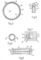
- Seal 42 (see also Figure 3) is annular and housed in a circular depression 44 formed in surface 24 of head 16, adjacent to seat 27, so that seal 42 engages both flat surface 26 of body 8 and cylindrical surface 13 of cylinder 7.
- Seal 42 ( Figure 4) has a substantially rectangular section with two major sides 45 perpendicular to, and two minor sides 46 parallel to, the axis of seal 42.
- Seal 43 ( Figures 1 and 5) is also annular but smaller in diameter than seal 42, and is housed inside a circular groove 49 formed in surface 24 of head 16 and concentric with inlet 38. Groove 49 is completely separate from depression 44 to prevent seals 42 and 43 contacting each other.
- Seal 43 has an oblong section with a major axis parallel to the axis of seal 43 ( Figure 6) and perpendicular to surface 24 of head 16.
- the oblong section is substantially hexagonal, and comprises two major sides 51 parallel to each other and to the major axis of the section, so that each of sides 51 defines the section of a corresponding cylindrical wall.
- the oblong section also comprises two pairs of sides 52 at an angle to each other and connected by a fillet 53; and the cylindrical surface corresponding to each side 51 has a central annular reinforcing rib 54.
- cylinder 7, together with piston 6 and spring 23, is first inserted inside seat 28 in body 8 (Figure 1); plate 9, together with valves 11 and 12, is then inserted inside oval depression 31 in head 16; seals 42 and 43 are inserted inside depression 44 (see also Figure 2) and groove 49 respectively; and, finally, head 16 is fitted to body 8 by means of screws inserted inside corresponding seats 55 on head 16.
- seals 42 and 43 are prevented from clogging intake conduit 33; seal 42 seals the entire cylindrical surface 13 of cylinder 7; and the in-service shape of the section of seal 43 ensures effective sealing of the connection between conduit 39 of body 8 and conduit 33 of head 16.
- the pump may comprise only one cylinder 7 or a number of in-line cylinders; plate 9 may be dispensed with and valves 11 and 12 located directly on head 16; at least one of seats 44 and 49 of seals 42 and 43 may be formed wholly or partly in flat surface 26 of body 8; and seal 43 may have an oblong section other than that shown in Figure 6.
Landscapes
- Engineering & Computer Science (AREA)
- Mechanical Engineering (AREA)
- General Engineering & Computer Science (AREA)
- Chemical & Material Sciences (AREA)
- Combustion & Propulsion (AREA)
- Fuel-Injection Apparatus (AREA)
- Details Of Reciprocating Pumps (AREA)
Description
- The present invention relates to improvements to a high-pressure pump for feeding fuel to an internal combustion engine, in particular a vehicle engine.
- High-pressure pumps of the above type normally comprise a body housing at least one cylinder in which a piston slides; and a head having a surface engaging a corresponding surface of the body to fix the cylinder. The head also has an intake conduit, the inlet of which is located at the head surface next to the cylinder seat.
- In one known radial-cylinder pump, each cylinder is fixed by a corresponding head; a single seal of elastomeric material is inserted between the surface of each head and the body surface, and comprises an arc-shaped portion of a given diameter, which fits about the cylinder, and a smaller-diameter arc-shaped portion, which fits about the intake conduit inlet; and the section of the seal is normally elongated in a direction parallel to the head surface.
- A major drawback of the above known pump lies in the seal stretching when subjected to high temperature. At pump temperatures of over 140°C, in particular, the seal tends to close at the connecting regions of the two arc-shaped portions, thus possibly choking or closing the inlet of the intake conduit. Moreover, since the choking effect differs from one cylinder to another, both activation and delivery of the pump are unbalanced, thus resulting in possible damage to the pump and in irregular supply to the engine.
- It is an object of the present invention to provide straightforward, reliable improvements to the seals of a high-pressure pump, to eliminate the aforementioned drawbacks typically associated with known pumps.
- According to the present invention, there is provided a high-pressure pump for feeding fuel to an internal combustion engine, and which comprises a body housing at least one cylinder in which a piston slides, and a head having a mating surface facing a corresponding mating surface on said body to fix said cylinder; said head having an intake conduit and a delivery conduit; said intake conduit having an inlet located at the mating surface of said head; and said body having a feed conduit having an outlet located at the mating surface of said body and at said inlet; characterized in that, between said mating surfaces, a first seal is placed about said cylinder, and a second seal about said inlet; said seals being separate and made of elastomeric material.
- A preferred, non-limiting embodiment of the invention will be described by way of example with reference to the accompanying drawings, in which:
- Figure 1 shows a partly sectioned view of a high-pressure pump incorporating the improvements according to the invention;
- Figure 2 shows a larger-scale view, along line II-II in Figure 1, of a head on the pump;
- Figure 3 shows a plan view of a first seal of the Figure 1 pump;
- Figure 4 shows a larger-scale partial section along line IV-IV in Figure 3;
- Figure 5 shows a plan view of a second seal of the Figure 1 pump;
- Figure 6 shows a larger-scale partial section along line VI-VI in Figure 5;
- Figure 7 shows the Figure 6 section in use.
-
-
Number 5 in Figure 1 indicates as a whole a high-pressure pump for feeding fuel to an internal combustion engine, e.g. of a vehicle.Pump 5 is of the type comprising threeradial pistons 6 sliding inside three cylinders 7 arranged radially inside a hollow body 8; and each cylinder 7 is closed at the top by a substantially oval plate 9. - Plate 9 has two flat
parallel surfaces 10, and supports an intake valve 11 coaxial with cylinder 7, and a delivery valve 12 eccentric with respect to cylinder 7. Each cylinder 7 has a cylindricallateral surface 13 defined by a flat surface 14 engaging one offlat surfaces 10 of plate 9; and each cylinder 7 and respective plate 9 are locked to body 8 by acorresponding lock head 16 fitted removably to body 8. - Pistons 6 are activated in sequence by a
single cam 17 integral with a shaft 18 activated by the internal combustion engine drive shaft;cam 17 acts onpistons 6 via aring 19 having, for eachpiston 6, a faced portion 21 cooperating with ashoe 22 fixed topiston 6; and eachshoe 22 is pushed towardscam 17 by acorresponding compression spring 23. - Each
head 16 comprises a preferablyflat mating surface 24 facing a correspondingflat mating surface 26 of body 8; and a cylindrical seat 27 (see also Figure 2) for housing a portion of cylinder 7 defined bylateral surface 13. Body 8 comprises a furthercylindrical seat 28 for housing the rest of cylinder 7 defined bysurface 13;seat 27 comprises aflat surface 29 in which is formed adepression 31 forming an oval seat for housing corresponding plate 9; and aflat surface 32 ofdepression 31 engages the other offlat surfaces 10 of plate 9. - Each
head 16 has anintake conduit 33 and a delivery conduit 34;intake conduit 33 comprises a portion defined by agroove 35 insurface 32;groove 35 is closed at the bottom by plate 9, and is aligned with aportion 36 ofconduit 33 perpendicular to the axis of cylinder 7; and conduit 34 comprises a portion 30 also perpendicular to the axis of cylinder 7. -
Intake conduit 33 also comprises a portion 37 parallel to the axis of cylinder 7, and which has aninlet 38 located atsurface 24 ofhead 16; and body 8 comprises afeed conduit 39 having anoutlet 41 located atsurface 26, and which is positioned, in use, atinlet 38. - According to the invention, between
surface 24 ofhead 16 andsurface 26 of body 8, afirst seal 42 is fitted about cylinder 7, and asecond seal 43 is fitted aboutinlet 38 ofconduit 33 andoutlet 41 ofconduit 39.Seals - Seal 42 (see also Figure 3) is annular and housed in a
circular depression 44 formed insurface 24 ofhead 16, adjacent toseat 27, so thatseal 42 engages bothflat surface 26 of body 8 andcylindrical surface 13 of cylinder 7. - Seal 42 (Figure 4) has a substantially rectangular section with two
major sides 45 perpendicular to, and twominor sides 46 parallel to, the axis ofseal 42. The surfaces ofseal 42, whose section forms the twomajor sides 45, each have aconvex rib 47 of a thickness ranging between 1/3 and 1/4 of theminor side 46 of the section; and the cylindrical surface forming theouter side 46 of the section has a number of small projections 48 (Figure 3) for preventingseal 42 from rotating insidedepression 44. - Seal 43 (Figures 1 and 5) is also annular but smaller in diameter than
seal 42, and is housed inside acircular groove 49 formed insurface 24 ofhead 16 and concentric withinlet 38. Groove 49 is completely separate fromdepression 44 to preventseals -
Seal 43 has an oblong section with a major axis parallel to the axis of seal 43 (Figure 6) and perpendicular tosurface 24 ofhead 16. The oblong section is substantially hexagonal, and comprises twomajor sides 51 parallel to each other and to the major axis of the section, so that each ofsides 51 defines the section of a corresponding cylindrical wall. The oblong section also comprises two pairs ofsides 52 at an angle to each other and connected by afillet 53; and the cylindrical surface corresponding to eachside 51 has a central annular reinforcingrib 54. - To assemble the pump, cylinder 7, together with
piston 6 andspring 23, is first inserted insideseat 28 in body 8 (Figure 1); plate 9, together with valves 11 and 12, is then inserted insideoval depression 31 inhead 16;seals groove 49 respectively; and, finally,head 16 is fitted to body 8 by means of screws inserted insidecorresponding seats 55 onhead 16. - The screws are tightened so that
surface 10 of plate 9 engages flat surface 14 of cylinder 7, andseals flat surface 26 of body 8.Seal 42 tends to deform radially and is forced againstsurface 13 of cylinder 7. Seal 43 (Figure 7), on the other hand, is deformed so that the two major sides (51) of the section arc into a C shape, with the concavity of the deformed section facing the axis ofseal 43, thus greatly improving sealing performance. - Tests have shown that, for a given pressure in
feed conduit 39, the volumetric efficiency of the pump is greatly improved with respect to a known pump featuring a common seal for the cylinder and the intake conduit. - As compared with known pumps, the advantages of the high-pressure pump according to the invention will be clear from the foregoing description. In particular, deformation of
seals clogging intake conduit 33;seal 42 seals the entirecylindrical surface 13 of cylinder 7; and the in-service shape of the section ofseal 43 ensures effective sealing of the connection betweenconduit 39 of body 8 andconduit 33 ofhead 16. - Clearly, changes may be made to the pump as described herein without, however, departing from the scope of the accompanying Claims. For example, the pump may comprise only one cylinder 7 or a number of in-line cylinders; plate 9 may be dispensed with and valves 11 and 12 located directly on
head 16; at least one ofseats seals flat surface 26 of body 8; andseal 43 may have an oblong section other than that shown in Figure 6.
Claims (10)
- A high-pressure pump for feeding fuel to an internal combustion engine, and which comprises a body (8) housing at least one cylinder (7) in which a piston (6) slides, and a head (16) having a mating surface (24) facing a corresponding mating surface (26) on said body (8) to fix said cylinder (7); said head (16) having an intake conduit (33) and a delivery conduit (34); said intake conduit (33) having an inlet (38) located at the mating surface (24) of said head (16); and said body (8) having a feed conduit (39) having an outlet (41) located at the mating surface (26) of said body (8) and at said inlet (38); characterized in that, between said mating surfaces (24, 26), a first seal (42) is placed about said cylinder (7), and a second seal (43) about said inlet (38); said seals (42, 43) being separate and made of elastomeric material.
- A high-pressure pump as claimed in Claim 1, wherein said cylinder (7) comprises a lateral surface (13) engaging a seat (27) in said head (16) and a seat (28) in said body (8); characterized in that said first seal (42) is housed in a circular depression (44) formed in one of or both said mating surfaces (24, 26), so as to enable said first seal (42) to engage said lateral surface (13).
- A high-pressure pump as claimed in Claim 2, characterized in that said second seal (43) is housed inside a circular groove (49) formed in one of or both said mating surfaces (24, 26) and concentric with said inlet (38) and said outlet (41); said groove (49) being separate from said depression (44).
- A high-pressure pump as claimed in Claim 2 or 3, characterized in that said first seal (42) has a substantially rectangular section with two major sides (45) perpendicular to the axis of said first seal (42); each of said major sides (45) having a rib (47) of a thickness ranging between 1/3 and 1/4 of the minor side (46) of said section.
- A high-pressure pump as claimed in Claim 4, characterized in that said first seal (42) has a cylindrical outer surface having a number of projections (48) for preventing said first seal (42) from rotating in said depression (44).
- A high-pressure pump as claimed in one of Claims 3 to 5, characterized in that said second seal (43) has an oblong section having a major axis parallel to the axis of said second seal (43).
- A high-pressure pump as claimed in Claim 6, characterized in that said oblong section is substantially hexagonal and comprises two parallel major sides (51), and two pairs of sides (52) at an angle to each other; said major sides (51) of said oblong section being parallel to said major axis; and the sides (52) in each of said pairs being connected by a fillet (53).
- A high-pressure pump as claimed in Claim 7, characterized in that, in use, said oblong section is deformed to arc said two major sides (51) of said oblong section.
- A high-pressure pump as claimed in one of the foregoing Claims, characterized in that, between said head (16) and said cylinder (7), there is inserted a plate (9) supporting an intake valve (11) and a delivery valve (12); each of said conduits (33, 34) comprising at least one portion (36, 30) perpendicular to the axis of said cylinder (7); said intake conduit (33) comprising a further portion (37) parallel to the axis of said cylinder (7) and having said inlet (38).
- A high-pressure pump as claimed in Claim 9, characterized by comprising a number of cylinders (7) arranged radially inside said body (8); and a number of pistons (6) associated with said cylinders (7) and sliding radially; each of said cylinders (7) being fixed to said body (8) by a corresponding head (16); and said body (8) comprising a feed conduit (39) associated with each of said cylinders (7).
Applications Claiming Priority (2)
| Application Number | Priority Date | Filing Date | Title |
|---|---|---|---|
| ITTO990574 | 1999-07-02 | ||
| IT1999TO000574A IT1308782B1 (en) | 1999-07-02 | 1999-07-02 | IMPROVEMENTS TO A HIGH PRESSURE PUMP FOR THE FUEL SUPPLY TO AN INTERNAL COMBUSTION ENGINE. |
Publications (3)
| Publication Number | Publication Date |
|---|---|
| EP1065369A2 EP1065369A2 (en) | 2001-01-03 |
| EP1065369A3 EP1065369A3 (en) | 2001-08-22 |
| EP1065369B1 true EP1065369B1 (en) | 2005-03-16 |
Family
ID=11417934
Family Applications (1)
| Application Number | Title | Priority Date | Filing Date |
|---|---|---|---|
| EP00113949A Expired - Lifetime EP1065369B1 (en) | 1999-07-02 | 2000-06-30 | Improvements to a high-pressure pump for feeding fuel to an internal combustion engine |
Country Status (8)
| Country | Link |
|---|---|
| US (1) | US6439859B1 (en) |
| EP (1) | EP1065369B1 (en) |
| JP (1) | JP4598244B2 (en) |
| KR (1) | KR100728741B1 (en) |
| CN (1) | CN1138916C (en) |
| DE (1) | DE60018640T2 (en) |
| IT (1) | IT1308782B1 (en) |
| RU (1) | RU2247256C2 (en) |
Families Citing this family (4)
| Publication number | Priority date | Publication date | Assignee | Title |
|---|---|---|---|---|
| FR2794811B1 (en) * | 1999-06-08 | 2003-02-07 | Peugeot Citroen Automobiles Sa | HIGH PRESSURE PUMP WITH IMPROVED SEALING |
| DE10310124B4 (en) * | 2003-03-07 | 2009-09-10 | Continental Automotive Gmbh | gasket |
| DE10310123A1 (en) * | 2003-03-07 | 2004-09-23 | Siemens Ag | Radial piston pump |
| DE102007048853A1 (en) * | 2007-10-11 | 2009-04-16 | Robert Bosch Gmbh | Flange of a high pressure fuel pump |
Family Cites Families (9)
| Publication number | Priority date | Publication date | Assignee | Title |
|---|---|---|---|---|
| US5102312A (en) * | 1990-08-30 | 1992-04-07 | Butterworth Jetting System, Inc. | Pump head |
| DE9013630U1 (en) * | 1990-09-28 | 1991-01-31 | Speck-Kolbenpumpenfabrik Otto Speck GmbH & Co. KG, 8192 Geretsried | High pressure liquid pump |
| RU2003823C1 (en) * | 1991-06-21 | 1993-11-30 | Центральный научно-исследовательский дизельный институт | Fuel-injecting high-pressure pump for internal combustion engine |
| US5215449A (en) * | 1991-12-05 | 1993-06-01 | Stanadyne Automotive Corp. | Distributor type fuel injection pump |
| DE4401074B4 (en) * | 1994-01-15 | 2007-01-18 | Robert Bosch Gmbh | Pump arrangement, in particular for conveying fuel from a reservoir to an internal combustion engine |
| DE19652831B4 (en) * | 1996-12-18 | 2011-02-24 | Continental Automotive Gmbh | Pressure fluid feed system for the supply of high pressure manifolds |
| DE19729789A1 (en) * | 1997-07-11 | 1999-01-14 | Bosch Gmbh Robert | Radial piston pump for high-pressure fuel supply |
| DE19758485B4 (en) * | 1997-07-11 | 2006-03-09 | Robert Bosch Gmbh | Sealing element for pressure medium lines |
| US6173965B1 (en) * | 1998-12-28 | 2001-01-16 | Leopold J. Niessen | Actuator seal bearing assembly and method |
-
1999
- 1999-07-02 IT IT1999TO000574A patent/IT1308782B1/en active
-
2000
- 2000-06-30 RU RU2000117612/06A patent/RU2247256C2/en not_active IP Right Cessation
- 2000-06-30 EP EP00113949A patent/EP1065369B1/en not_active Expired - Lifetime
- 2000-06-30 KR KR1020000037211A patent/KR100728741B1/en not_active Expired - Fee Related
- 2000-06-30 US US09/608,381 patent/US6439859B1/en not_active Expired - Lifetime
- 2000-06-30 CN CNB00121702XA patent/CN1138916C/en not_active Expired - Fee Related
- 2000-06-30 DE DE60018640T patent/DE60018640T2/en not_active Expired - Lifetime
- 2000-07-03 JP JP2000201011A patent/JP4598244B2/en not_active Expired - Fee Related
Also Published As
| Publication number | Publication date |
|---|---|
| EP1065369A3 (en) | 2001-08-22 |
| EP1065369A2 (en) | 2001-01-03 |
| ITTO990574A1 (en) | 2001-01-02 |
| CN1284604A (en) | 2001-02-21 |
| US6439859B1 (en) | 2002-08-27 |
| DE60018640D1 (en) | 2005-04-21 |
| DE60018640T2 (en) | 2006-04-27 |
| RU2247256C2 (en) | 2005-02-27 |
| KR100728741B1 (en) | 2007-06-19 |
| IT1308782B1 (en) | 2002-01-10 |
| KR20010015124A (en) | 2001-02-26 |
| CN1138916C (en) | 2004-02-18 |
| JP4598244B2 (en) | 2010-12-15 |
| JP2001050138A (en) | 2001-02-23 |
Similar Documents
| Publication | Publication Date | Title |
|---|---|---|
| US5626121A (en) | Fuel pump for high-pressure fuel injection system | |
| US6289875B1 (en) | Fuel injection pump | |
| US7152518B2 (en) | Structure of fuel injection pump for extending service life | |
| JP4384043B2 (en) | High pressure pumps, especially for fuel injection devices of internal combustion engines | |
| JP4199930B2 (en) | Piston pump for high-pressure fuel supply | |
| JP5862580B2 (en) | High pressure fuel pump | |
| US10876509B2 (en) | High-pressure fuel pump | |
| US20160138489A1 (en) | High-pressure pump and fuel injection system having a high-pressure pump | |
| JP2004537005A (en) | High pressure supply pump | |
| US6439859B1 (en) | High-pressure pump for feeding fuel to an internal combustion engine | |
| EP0843091A1 (en) | Injector mounting structure for engines | |
| CN102844559B (en) | High-pressure service pump | |
| CN115698505A (en) | Gas supply pump for dual-fuel engine of ship | |
| JP2001500223A (en) | Radial piston pump for high pressure fuel supply | |
| US20020034452A1 (en) | High-pressure hydraulic fuel pump | |
| US10584700B1 (en) | High-pressure fuel pump | |
| JP2002509224A (en) | Radial piston pump for high pressure fuel supply | |
| US20040247464A1 (en) | Fuel supply apparatus | |
| JP2000087824A (en) | Radial piston pump | |
| RU2000117612A (en) | IMPROVEMENTS IN A HIGH PRESSURE PUMP FOR SUPPLYING FUEL TO THE INTERNAL COMBUSTION ENGINE | |
| JP2002317730A (en) | Fuel injection device | |
| US20260139646A1 (en) | Gas supply pump for ship dual fuel engine | |
| JPH09209931A (en) | Piston type compressor | |
| JPH08232852A (en) | Fuel pump | |
| JP2002364480A (en) | Fuel supply device |
Legal Events
| Date | Code | Title | Description |
|---|---|---|---|
| PUAI | Public reference made under article 153(3) epc to a published international application that has entered the european phase |
Free format text: ORIGINAL CODE: 0009012 |
|
| AK | Designated contracting states |
Kind code of ref document: A2 Designated state(s): DE ES FR GB IT SE Kind code of ref document: A2 Designated state(s): AT BE CH CY DE DK ES FI FR GB GR IE IT LI LU MC NL PT SE |
|
| AX | Request for extension of the european patent |
Free format text: AL;LT;LV;MK;RO;SI |
|
| RAP1 | Party data changed (applicant data changed or rights of an application transferred) |
Owner name: ROBERT BOSCH GMBH |
|
| PUAL | Search report despatched |
Free format text: ORIGINAL CODE: 0009013 |
|
| AK | Designated contracting states |
Kind code of ref document: A3 Designated state(s): AT BE CH CY DE DK ES FI FR GB GR IE IT LI LU MC NL PT SE |
|
| AX | Request for extension of the european patent |
Free format text: AL;LT;LV;MK;RO;SI |
|
| RIC1 | Information provided on ipc code assigned before grant |
Free format text: 7F 02M 59/44 A, 7F 02M 63/02 B, 7F 04B 53/00 B, 7F 04B 1/04 B |
|
| 17P | Request for examination filed |
Effective date: 20020219 |
|
| AKX | Designation fees paid |
Free format text: DE ES FR GB IT SE |
|
| GRAP | Despatch of communication of intention to grant a patent |
Free format text: ORIGINAL CODE: EPIDOSNIGR1 |
|
| GRAA | (expected) grant |
Free format text: ORIGINAL CODE: 0009210 |
|
| GRAS | Grant fee paid |
Free format text: ORIGINAL CODE: EPIDOSNIGR3 |
|
| AK | Designated contracting states |
Kind code of ref document: B1 Designated state(s): DE ES FR GB IT SE |
|
| REG | Reference to a national code |
Ref country code: GB Ref legal event code: FG4D |
|
| REF | Corresponds to: |
Ref document number: 60018640 Country of ref document: DE Date of ref document: 20050421 Kind code of ref document: P |
|
| PG25 | Lapsed in a contracting state [announced via postgrant information from national office to epo] |
Ref country code: ES Free format text: LAPSE BECAUSE OF FAILURE TO SUBMIT A TRANSLATION OF THE DESCRIPTION OR TO PAY THE FEE WITHIN THE PRESCRIBED TIME-LIMIT Effective date: 20050627 |
|
| PLBE | No opposition filed within time limit |
Free format text: ORIGINAL CODE: 0009261 |
|
| STAA | Information on the status of an ep patent application or granted ep patent |
Free format text: STATUS: NO OPPOSITION FILED WITHIN TIME LIMIT |
|
| ET | Fr: translation filed | ||
| 26N | No opposition filed |
Effective date: 20051219 |
|
| PG25 | Lapsed in a contracting state [announced via postgrant information from national office to epo] |
Ref country code: SE Free format text: LAPSE BECAUSE OF FAILURE TO SUBMIT A TRANSLATION OF THE DESCRIPTION OR TO PAY THE FEE WITHIN THE PRESCRIBED TIME-LIMIT Effective date: 20050616 |
|
| PGFP | Annual fee paid to national office [announced via postgrant information from national office to epo] |
Ref country code: GB Payment date: 20130620 Year of fee payment: 14 |
|
| PGFP | Annual fee paid to national office [announced via postgrant information from national office to epo] |
Ref country code: FR Payment date: 20130703 Year of fee payment: 14 |
|
| PGFP | Annual fee paid to national office [announced via postgrant information from national office to epo] |
Ref country code: IT Payment date: 20130621 Year of fee payment: 14 |
|
| GBPC | Gb: european patent ceased through non-payment of renewal fee |
Effective date: 20140630 |
|
| REG | Reference to a national code |
Ref country code: FR Ref legal event code: ST Effective date: 20150227 |
|
| PG25 | Lapsed in a contracting state [announced via postgrant information from national office to epo] |
Ref country code: IT Free format text: LAPSE BECAUSE OF NON-PAYMENT OF DUE FEES Effective date: 20140630 |
|
| PG25 | Lapsed in a contracting state [announced via postgrant information from national office to epo] |
Ref country code: FR Free format text: LAPSE BECAUSE OF NON-PAYMENT OF DUE FEES Effective date: 20140630 Ref country code: GB Free format text: LAPSE BECAUSE OF NON-PAYMENT OF DUE FEES Effective date: 20140630 |
|
| PGFP | Annual fee paid to national office [announced via postgrant information from national office to epo] |
Ref country code: DE Payment date: 20180807 Year of fee payment: 19 |
|
| REG | Reference to a national code |
Ref country code: DE Ref legal event code: R119 Ref document number: 60018640 Country of ref document: DE |
|
| PG25 | Lapsed in a contracting state [announced via postgrant information from national office to epo] |
Ref country code: DE Free format text: LAPSE BECAUSE OF NON-PAYMENT OF DUE FEES Effective date: 20200101 |