EP1065143A1 - Cigarette packing machine - Google Patents
Cigarette packing machine Download PDFInfo
- Publication number
- EP1065143A1 EP1065143A1 EP00113506A EP00113506A EP1065143A1 EP 1065143 A1 EP1065143 A1 EP 1065143A1 EP 00113506 A EP00113506 A EP 00113506A EP 00113506 A EP00113506 A EP 00113506A EP 1065143 A1 EP1065143 A1 EP 1065143A1
- Authority
- EP
- European Patent Office
- Prior art keywords
- machine
- carriage
- conveyor
- guide
- along
- Prior art date
- Legal status (The legal status is an assumption and is not a legal conclusion. Google has not performed a legal analysis and makes no representation as to the accuracy of the status listed.)
- Granted
Links
- 235000019504 cigarettes Nutrition 0.000 title claims abstract description 29
- 238000012856 packing Methods 0.000 title claims abstract description 16
- 239000000463 material Substances 0.000 claims description 3
- 230000003287 optical effect Effects 0.000 claims 1
- 230000001360 synchronised effect Effects 0.000 claims 1
- 238000004804 winding Methods 0.000 description 2
- 230000000694 effects Effects 0.000 description 1
- 239000000284 extract Substances 0.000 description 1
- 230000003993 interaction Effects 0.000 description 1
- 238000005192 partition Methods 0.000 description 1
Images

Classifications
-
- B—PERFORMING OPERATIONS; TRANSPORTING
- B65—CONVEYING; PACKING; STORING; HANDLING THIN OR FILAMENTARY MATERIAL
- B65B—MACHINES, APPARATUS OR DEVICES FOR, OR METHODS OF, PACKAGING ARTICLES OR MATERIALS; UNPACKING
- B65B19/00—Packaging rod-shaped or tubular articles susceptible to damage by abrasion or pressure, e.g. cigarettes, cigars, macaroni, spaghetti, drinking straws or welding electrodes
- B65B19/02—Packaging cigarettes
- B65B19/04—Arranging, feeding, or orientating the cigarettes
- B65B19/10—Arranging cigarettes in layers each comprising a predetermined number
-
- B—PERFORMING OPERATIONS; TRANSPORTING
- B65—CONVEYING; PACKING; STORING; HANDLING THIN OR FILAMENTARY MATERIAL
- B65G—TRANSPORT OR STORAGE DEVICES, e.g. CONVEYORS FOR LOADING OR TIPPING, SHOP CONVEYOR SYSTEMS OR PNEUMATIC TUBE CONVEYORS
- B65G2201/00—Indexing codes relating to handling devices, e.g. conveyors, characterised by the type of product or load being conveyed or handled
- B65G2201/02—Articles
- B65G2201/0226—Cigarettes
Definitions
- the present invention relates to a cigarette packing machine.
- Known cigarette packing machines such as the type described in Patent US 3,707,219, comprise a conveyor for step feeding a number of forming and conveying pockets along a path extending parallel to a number of hopper outlets.
- a reciprocating pusher extracts one or more layers of cigarettes from each outlet of the hopper into a respective pocket arrested in front of the hopper; which operation may be repeated at successive stops of the conveyor until a complete group of cigarettes defining the content of a packet is formed inside each pocket.
- the complete groups are extracted successively from the conveyor pockets onto a step-operated or continuous wrapping unit.
- group-forming units of the type described above have the drawback of being unable to operate at relatively high speed, on account of intermittent operation of the conveyor, and the difficulty posed in connecting the unit to a continuous wrapping unit. Moreover, such forming units also have a relatively high noise level.
- a cigarette packing machine comprising a conveyor having at least one pocket for forming and conveying a respective group of cigarettes; the machine being characterized in that said conveyor comprises a fixed guide; at least one carriage running along said guide and supporting said pocket; and a linear electric motor having a stator or primary located along at least a portion of the guide, and a cursor or secondary carried by said carriage.
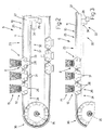
- Number 1 in Figure 1 indicates as a whole a machine for packing cigarettes 2, and comprising a forming unit 3 for forming groups 4 of cigarettes 2, and a known wrapping unit 5 (shown in block form in Figure 1).
- Unit 3 comprises a conveyor 6 in turn comprising two trains 7 of three carriages 8, each of which supports a respective pocket 9 for housing a respective group 4 of cigarettes 2.
- Each carriage 8 runs along a fixed endless guide 10 defining an endless path P lying in the Figure 1 plane and having two straight, parallel, horizontal portions P1 and P2 connected to each other by two semicircular portions P3 and P4.
- Guide 10 of conveyor 6 comprises a pair of parallel rails 11 (only one shown in Figure 1) in which are defined respective grooves 12 engaged transversely and in sliding manner by pins 13 on each carriage 8.
- the three carriages 8 in each train 7 are connected mechanically to one another by means of respective arms 14, each of which is hinged at opposite ends to the facing ends of a respective pair of adjacent carriages 8 to enable carriages 8 to rotate with respect to each other along the curved portions of path P.
- Forming unit 3 comprises a hopper 15 containing a mass (not shown) of cigarettes 2 oriented with their respective axes (not shown) perpendicular to path P and to the Figure 1 plane.
- Hopper 15 comprises two lateral walls 16; a front wall (not shown); a rear wall 17; and three outlets 18, each of which is defined by two lateral walls 19 and by a number of partitions 20 which, together with walls 19, define a number of substantially vertical downfeed channels 21 for cigarettes 2.
- Each outlet 18 is defined in known manner at the bottom end by a respective horizontal platform (not shown) on which the cigarettes 2 issuing from respective channels 21 come to rest to form a respective orderly group 4.
- Outlets 18 are arranged with a given spacing 22 along portion P1 of path P, and pockets 9 of each train 7 are also arranged with the same spacing 22 so that, when train 7 is set to a loading position in front of hopper 15, each pocket 9 is positioned facing and aligned with a respective outlet 18, and groups 4 of cigarettes 2 inside respective outlets 18 may be fed into respective pockets 9 by means of a known extracting device (not shown), in particular a reciprocating pusher.
- the number N of outlets 18 of hopper 15 is other than three, and in particular is a multiple of the number of pockets 9 in each train 7.
- the known extracting device (not shown) feeds only one layer of cigarettes 2 at a time into a respective pocket 9, so that each pocket 9 must be arrested successively in front of three different outlets 18 to receive a respective layer of cigarettes 2 from each.
- carriages 8 are run along guide 10 by an actuating device 23 comprising a linear electric motor 24 having a primary or stator 25 located along guide 10, and a series of secondaries or cursors 26, each carried by a respective carriage 8.
- actuating device 23 comprising a linear electric motor 24 having a primary or stator 25 located along guide 10, and a series of secondaries or cursors 26, each carried by a respective carriage 8.
- each train 7 is provided with only one secondary 26 carried by a drive carriage 8, which drives the other nonpowered carriages 8.
- primary 25 of linear electric motor 24 comprises a pair of longitudinal members 27 (only one shown in the accompanying drawings) extending parallel to and inside rails 11, and supporting a series of known electric windings (not shown) for generating a variable magnetic field between members 27; each secondary 26 comprises a pair of permanent magnets 28 spaced a given distance D apart and connected mechanically to a respective carriage 8 so as to be located between members 27; and the gap between magnets 28 and members 27 is relatively small (about 1-2 millimeters) to achieve relatively powerful driving forces on carriages 8 while at the same time preventing magnets 28 from sliding against members 27.
- actuating device 23 also comprises a control unit 29, which drives the windings of primary 25 by means of a closed-loop (i.e. feedback) control system; for which purpose, control unit 29 is connected to a sensor 30 for detecting, instant by instant, the position of each carriage 8 or each train 7 of carriages 8 along path P.
- control unit 29 is connected to a sensor 30 for detecting, instant by instant, the position of each carriage 8 or each train 7 of carriages 8 along path P.
- Sensor 30 comprises a reference member 31 carried by one carriage 8 in each train 7; and a fixed reading system 32 connected to reference member 31.
- each carriage 8 carries a respective reference member 31 for redundant control of the position of trains 7 along path P.
- reference member 31 is defined by a permanent magnet connected magnetically to a bar 33 of magnetostrictive material forming part of reading system 32, which comprises a measuring unit 34 connected to one end of bar 33 to accurately determine the position of member 31 and, hence, of respective train 7.
- measuring unit 34 produces a mechanical stress which travels like a sound wave along bar 33; at member 31, bar 33 is of uneven shape on account of the magnetostrictive effect induced by the magnetic field produced by member 31; and the unevenness produces in the sound wave a reflection component which travels, at the speed of sound in bar 33, back to measuring unit 34, which determines the distance between itself and reference member 31 by measuring the time interval between the instant the wave is emitted and the instant the reflected component is received.
- reference member 31 is defined by a permanent magnet connected magnetically to a bar 33 forming part of reading system 32 and having a number of known magnetoresistors (not shown) equally spaced along bar 33 with a relatively small spacing; and reading system 32 comprises a measuring unit 34 connected electrically to one end of bar 33 to accurately determine the position of member 31 and, hence, of respective train 7 by cyclically measuring the resistance value of the magnetoresistors on bar 33, and so determining the point at which the resistance value changes as a result of the magnetic field produced by reference member 31.
- reference member 31 is defined by a reflecting prism for reflecting a laser light pulse emitted by a measuring unit 34, which forms part of reading system 32 and provides for determining the distance between itself and reference member 31 by measuring the time interval between the instant the laser pulse is emitted and the instant the reflected component is received.
- a sensor 30 comprising a magnet 31 connected to a bar 33 of magnetostrictive material, or to a bar 33 with magnetoresistors, may be used to determine the position of a train 7 along straight path portions such as P1 and P2, as well as along nonstraight path portions such as P4; whereas a sensor 30 comprising a prism 31 connected to a laser emitter 34 may only be used to determine the position of a train 7 along straight path portions such as P1 and P2.
- Sensors 30 as described above provide for controlling the position of a train 7 of carriages 8 along path P to a fairly high degree of accuracy, as required along the portions of path P in which pockets 9 carried by train 7 are called upon to cooperate with other parts of packing machine 1, such as hopper 15 and wrapping unit 5.
- control unit 29 may drive primary 25 by means of an open-loop control system (i.e. with no feedback signal).
- each carriage 8 cooperates with, and transfers a respective group 4 of cigarettes 2 to, wrapping unit 5.
- portion P3 therefore, the law of motion of each train 7 of carriages 8 must be extremely precise, in that any error in the positioning of a carriage 8 may result in damage to the known transfer members (not shown) of wrapping unit 5.
- timing device 36 comprises a powered shaft 37 coaxial with axis 35; and two disks 38 (only one shown in Figure 4) fitted to shaft 37 and each supporting a number of permanent magnets 39, each facing a permanent magnet 39 on the other disk 38.
- Magnets 39 of each disk 38 are divided into pairs 40 equally spaced along disk 38 with the magnets 39 in each pair 40 separated by a distance equal to distance D; and disks 38 define, in between, a semicircular passage 41 through which travels the bottom portion of each carriage 8 supporting permanent magnets 28.
- Actuating device 23 moves train 7 successively, and at substantially constant speed, along straight portion P2, semicircular portion P4, and straight portion P1 up to hopper 15, in front of which, actuating device 23 stops train 7 temporarily in said loading position wherein each pocket 9 is positioned facing and aligned with a respective outlet 18, and wherein groups 4 of cigarettes 2 in respective outlets 18 are fed into respective pockets 9 by said known extracting device (not shown).
- Actuating device 23 then accelerates train 7 along the rest of portion P1 towards timing device 36, until the first carriage 8 in train 7 engages portion P3, where the bottom portion of carriage 8 engages passage 41, and the interacting magnetic forces established between the two permanent magnets 28 of carriage 8 and two corresponding pairs 40 of permanent magnets 39 on the two disks 38 move and lock carriage 8 into a given fixed position with respect to disks 38. From this moment on, train 7 is fed along portion P3 in perfect time with the rotation of disks 38, by each pair 40 of magnets 39 acting as a timing member to time carriages 8 with disks 38 along portion P3.
- the polarities of a permanent magnet 28 and of the two respective permanent magnets 39 facing magnet 28 in use must obviously be opposite at all times, so that the forces between magnets 28 and 39 are always of attraction and never of repulsion. This condition is met substantially at all times, by the positioning error of a train 7 of carriages 8 with respect to disks 38 being relatively small (about a few millimeters) at all times, and such as never to result in a relative position in which opposite polarities are positioned facing.
- Permanent magnets 28 therefore form part of both actuating device 23, as a secondary of linear electric motor 24, and timing device 36, as a magnetic connecting means, thus reducing the number of components involved.
- conveyor 6 comprises mechanical or magnetic stop means for arresting a train 7 of carriages 8 in a given position along path P, in particular in said loading position.
- each carriage 8 is connected to disks 38 by mechanical connecting means, e.g. a series of pins carried by disks 38, and each of which is movable axially to engage a respective seat defined on a respective carriage 8.
- mechanical connecting means e.g. a series of pins carried by disks 38, and each of which is movable axially to engage a respective seat defined on a respective carriage 8.
- Conveyor 6 as described above - for feeding a carriage 8 along a path P by means of a linear electric motor 24 comprising a primary or stator 25 located along at least one portion of path P, and a secondary or cursor 26 carried by carriage 8 - may be employed in various parts of the packing machine.
- a conveyor may be used to advantage for feeding an article along a path at speeds varying from one portion to another of the path, e.g. for feeding the article at constant speed (continuous operation) along one portion, and in steps (intermittent operation) along another portion.
- the law of motion of each carriage is independent of the position of the carriage along the path and of the law of motion of the other carriages.
Landscapes
- Engineering & Computer Science (AREA)
- Mechanical Engineering (AREA)
- Wrapping Of Specific Fragile Articles (AREA)
Abstract
Description
- The present invention relates to a cigarette packing machine.
- Known cigarette packing machines, such as the type described in Patent US 3,707,219, comprise a conveyor for step feeding a number of forming and conveying pockets along a path extending parallel to a number of hopper outlets. At each stop of the conveyor, a reciprocating pusher extracts one or more layers of cigarettes from each outlet of the hopper into a respective pocket arrested in front of the hopper; which operation may be repeated at successive stops of the conveyor until a complete group of cigarettes defining the content of a packet is formed inside each pocket.
- At a transfer station, the complete groups are extracted successively from the conveyor pockets onto a step-operated or continuous wrapping unit.
- Though perfectly functional, group-forming units of the type described above have the drawback of being unable to operate at relatively high speed, on account of intermittent operation of the conveyor, and the difficulty posed in connecting the unit to a continuous wrapping unit. Moreover, such forming units also have a relatively high noise level.
- It is an object of the present invention to provide a cigarette packing machine designed to eliminate the aforementioned drawbacks, and which, in particular, is straightforward mechanically.
- According to the present invention, there is provided a cigarette packing machine comprising a conveyor having at least one pocket for forming and conveying a respective group of cigarettes; the machine being characterized in that said conveyor comprises a fixed guide; at least one carriage running along said guide and supporting said pocket; and a linear electric motor having a stator or primary located along at least a portion of the guide, and a cursor or secondary carried by said carriage.
- A number of non-limiting embodiments of the present invention will be described by way of example with reference to the accompanying drawings, in which:
- Figure 1 shows a schematic side view, with parts removed for clarity, of a packing machine in accordance with the present invention;
- Figures 2 and 3 show side views of two different embodiments of the Figure 1 machine;
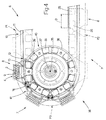
- Figure 4 shows a larger-scale side view, with parts removed for clarityity, of a detail of the conveyor in Figure 1, 2 or 3.
-
-
Number 1 in Figure 1 indicates as a whole a machine for packingcigarettes 2, and comprising a forming unit 3 for forminggroups 4 ofcigarettes 2, and a known wrapping unit 5 (shown in block form in Figure 1). - Unit 3 comprises a
conveyor 6 in turn comprising twotrains 7 of threecarriages 8, each of which supports arespective pocket 9 for housing arespective group 4 ofcigarettes 2. Eachcarriage 8 runs along a fixedendless guide 10 defining an endless path P lying in the Figure 1 plane and having two straight, parallel, horizontal portions P1 and P2 connected to each other by two semicircular portions P3 and P4.Guide 10 ofconveyor 6 comprises a pair of parallel rails 11 (only one shown in Figure 1) in which are definedrespective grooves 12 engaged transversely and in sliding manner bypins 13 on eachcarriage 8. - The three
carriages 8 in eachtrain 7 are connected mechanically to one another by means ofrespective arms 14, each of which is hinged at opposite ends to the facing ends of a respective pair ofadjacent carriages 8 to enablecarriages 8 to rotate with respect to each other along the curved portions of path P. - Forming unit 3 comprises a
hopper 15 containing a mass (not shown) ofcigarettes 2 oriented with their respective axes (not shown) perpendicular to path P and to the Figure 1 plane.Hopper 15 comprises twolateral walls 16; a front wall (not shown); arear wall 17; and threeoutlets 18, each of which is defined by twolateral walls 19 and by a number ofpartitions 20 which, together withwalls 19, define a number of substantially verticaldownfeed channels 21 forcigarettes 2. Eachoutlet 18 is defined in known manner at the bottom end by a respective horizontal platform (not shown) on which thecigarettes 2 issuing fromrespective channels 21 come to rest to form a respectiveorderly group 4. -
Outlets 18 are arranged with a givenspacing 22 along portion P1 of path P, andpockets 9 of eachtrain 7 are also arranged with thesame spacing 22 so that, whentrain 7 is set to a loading position in front ofhopper 15, eachpocket 9 is positioned facing and aligned with arespective outlet 18, andgroups 4 ofcigarettes 2 insiderespective outlets 18 may be fed intorespective pockets 9 by means of a known extracting device (not shown), in particular a reciprocating pusher. - In an alternative embodiment not shown, the number N of
outlets 18 ofhopper 15 is other than three, and in particular is a multiple of the number ofpockets 9 in eachtrain 7. In yet a further embodiment not shown, the known extracting device (not shown) feeds only one layer ofcigarettes 2 at a time into arespective pocket 9, so that eachpocket 9 must be arrested successively in front of threedifferent outlets 18 to receive a respective layer ofcigarettes 2 from each. - Along portions P1, P2 and P4 of path P,
carriages 8 are run alongguide 10 by an actuatingdevice 23 comprising a linearelectric motor 24 having a primary orstator 25 located alongguide 10, and a series of secondaries orcursors 26, each carried by arespective carriage 8. In an alternative embodiment not shown, eachtrain 7 is provided with only one secondary 26 carried by adrive carriage 8, which drives the othernonpowered carriages 8. - In the preferred embodiment shown in the accompanying drawings, primary 25 of linear
electric motor 24 comprises a pair of longitudinal members 27 (only one shown in the accompanying drawings) extending parallel to and insiderails 11, and supporting a series of known electric windings (not shown) for generating a variable magnetic field betweenmembers 27; each secondary 26 comprises a pair ofpermanent magnets 28 spaced a given distance D apart and connected mechanically to arespective carriage 8 so as to be located betweenmembers 27; and the gap betweenmagnets 28 andmembers 27 is relatively small (about 1-2 millimeters) to achieve relatively powerful driving forces oncarriages 8 while at the sametime preventing magnets 28 from sliding againstmembers 27. - As shown in Figures 2 and 3,
actuating device 23 also comprises acontrol unit 29, which drives the windings of primary 25 by means of a closed-loop (i.e. feedback) control system; for which purpose,control unit 29 is connected to asensor 30 for detecting, instant by instant, the position of eachcarriage 8 or eachtrain 7 ofcarriages 8 along path P. -
Sensor 30 comprises areference member 31 carried by onecarriage 8 in eachtrain 7; and afixed reading system 32 connected toreference member 31. In an alternative embodiment not shown, eachcarriage 8 carries arespective reference member 31 for redundant control of the position oftrains 7 along path P. - In one embodiment shown in Figure 2,
reference member 31 is defined by a permanent magnet connected magnetically to abar 33 of magnetostrictive material forming part ofreading system 32, which comprises ameasuring unit 34 connected to one end ofbar 33 to accurately determine the position ofmember 31 and, hence, ofrespective train 7. - More specifically, measuring
unit 34 produces a mechanical stress which travels like a sound wave alongbar 33; atmember 31,bar 33 is of uneven shape on account of the magnetostrictive effect induced by the magnetic field produced bymember 31; and the unevenness produces in the sound wave a reflection component which travels, at the speed of sound inbar 33, back to measuringunit 34, which determines the distance between itself andreference member 31 by measuring the time interval between the instant the wave is emitted and the instant the reflected component is received. - In an alternative embodiment shown in Figure 2,
reference member 31 is defined by a permanent magnet connected magnetically to abar 33 forming part ofreading system 32 and having a number of known magnetoresistors (not shown) equally spaced alongbar 33 with a relatively small spacing; andreading system 32 comprises ameasuring unit 34 connected electrically to one end ofbar 33 to accurately determine the position ofmember 31 and, hence, ofrespective train 7 by cyclically measuring the resistance value of the magnetoresistors onbar 33, and so determining the point at which the resistance value changes as a result of the magnetic field produced byreference member 31. - In an alternative embodiment shown in Figure 3,
reference member 31 is defined by a reflecting prism for reflecting a laser light pulse emitted by ameasuring unit 34, which forms part ofreading system 32 and provides for determining the distance between itself andreference member 31 by measuring the time interval between the instant the laser pulse is emitted and the instant the reflected component is received. - A
sensor 30 comprising amagnet 31 connected to abar 33 of magnetostrictive material, or to abar 33 with magnetoresistors, may be used to determine the position of atrain 7 along straight path portions such as P1 and P2, as well as along nonstraight path portions such as P4; whereas asensor 30 comprising aprism 31 connected to alaser emitter 34 may only be used to determine the position of atrain 7 along straight path portions such as P1 and P2. -
Sensors 30 as described above provide for controlling the position of atrain 7 ofcarriages 8 along path P to a fairly high degree of accuracy, as required along the portions of path P in whichpockets 9 carried bytrain 7 are called upon to cooperate with other parts ofpacking machine 1, such ashopper 15 and wrappingunit 5. - Along other portions of path P (e.g. P2 and P4), on the other hand, train 7 of
carriages 8 simply travels through with no interaction with other parts ofpacking machine 1, so that other known types of sensors 30 (less precise but cheaper) may be used along such portions of path P to determine the position oftrain 7 and generate the feedback signal to controlunit 29. Alternatively, along such portions of path P,control unit 29 may drive primary 25 by means of an open-loop control system (i.e. with no feedback signal). - Along semicircular portion P3 extending about a horizontal
central axis 35 perpendicular to the Figure 1 plane, eachcarriage 8 cooperates with, and transfers arespective group 4 ofcigarettes 2 to,wrapping unit 5. Along portion P3, therefore, the law of motion of eachtrain 7 ofcarriages 8 must be extremely precise, in that any error in the positioning of acarriage 8 may result in damage to the known transfer members (not shown) ofwrapping unit 5. For this reason, whereas, along portions P1, P2 and P4 of path P,carriages 8 are fed alongguide 10 by actuatingdevice 23,trains 7 ofcarriages 8 are fed along portion P3 by atiming device 36, which provides for feeding eachtrain 7 along portion P3 with a given law of motion and in time with the known transfer members (not shown) of wrappingunit 5 cooperating withcarriages 8 along portion P3. - As shown in Figure 4,
timing device 36 comprises a poweredshaft 37 coaxial withaxis 35; and two disks 38 (only one shown in Figure 4) fitted toshaft 37 and each supporting a number ofpermanent magnets 39, each facing apermanent magnet 39 on theother disk 38.Magnets 39 of eachdisk 38 are divided intopairs 40 equally spaced alongdisk 38 with themagnets 39 in eachpair 40 separated by a distance equal to distance D; anddisks 38 define, in between, asemicircular passage 41 through which travels the bottom portion of eachcarriage 8 supportingpermanent magnets 28. - Operation of
packing machine 1 will now be described with reference to Figures 1 and 4, and to onetrain 7 of threecarriages 8 traveling along portion P2 of path P. - Actuating
device 23 moves train 7 successively, and at substantially constant speed, along straight portion P2, semicircular portion P4, and straight portion P1 up to hopper 15, in front of which, actuatingdevice 23 stopstrain 7 temporarily in said loading position wherein eachpocket 9 is positioned facing and aligned with arespective outlet 18, and whereingroups 4 ofcigarettes 2 inrespective outlets 18 are fed intorespective pockets 9 by said known extracting device (not shown). - Actuating
device 23 then acceleratestrain 7 along the rest of portion P1 towardstiming device 36, until thefirst carriage 8 intrain 7 engages portion P3, where the bottom portion ofcarriage 8 engagespassage 41, and the interacting magnetic forces established between the twopermanent magnets 28 ofcarriage 8 and twocorresponding pairs 40 ofpermanent magnets 39 on the twodisks 38 move and lockcarriage 8 into a given fixed position with respect todisks 38. From this moment on,train 7 is fed along portion P3 in perfect time with the rotation ofdisks 38, by eachpair 40 ofmagnets 39 acting as a timing member totime carriages 8 withdisks 38 along portion P3. - Along portion P3,
groups 4 ofcigarettes 2 are transferred fromrespective pockets 9 ontrain 7 to wrappingunit 5, andtrain 7 is gradually released fromtiming device 36 on reaching portion P2. - The above operations are repeated cyclically.
- For
timing device 36 to work properly, the polarities of apermanent magnet 28 and of the two respectivepermanent magnets 39 facingmagnet 28 in use must obviously be opposite at all times, so that the forces betweenmagnets train 7 ofcarriages 8 with respect todisks 38 being relatively small (about a few millimeters) at all times, and such as never to result in a relative position in which opposite polarities are positioned facing. -
Permanent magnets 28 therefore form part of both actuatingdevice 23, as a secondary of linearelectric motor 24, andtiming device 36, as a magnetic connecting means, thus reducing the number of components involved. - In an alternative embodiment not shown,
conveyor 6 comprises mechanical or magnetic stop means for arresting atrain 7 ofcarriages 8 in a given position along path P, in particular in said loading position. - In a further embodiment not shown, each
carriage 8 is connected todisks 38 by mechanical connecting means, e.g. a series of pins carried bydisks 38, and each of which is movable axially to engage a respective seat defined on arespective carriage 8. -
Conveyor 6 as described above - for feeding acarriage 8 along a path P by means of a linearelectric motor 24 comprising a primary orstator 25 located along at least one portion of path P, and a secondary orcursor 26 carried by carriage 8 - may be employed in various parts of the packing machine. In particular, such a conveyor may be used to advantage for feeding an article along a path at speeds varying from one portion to another of the path, e.g. for feeding the article at constant speed (continuous operation) along one portion, and in steps (intermittent operation) along another portion. In such a conveyor, in fact, the law of motion of each carriage is independent of the position of the carriage along the path and of the law of motion of the other carriages.
Claims (19)
- A cigarette packing machine comprising a conveyor (6) having at least one pocket (9) for forming and conveying a respective group (4) of cigarettes (2); the machine (1) being characterized in that said conveyor (6) comprises a fixed guide (10); at least one carriage (8) running along said guide (10) and supporting said pocket (9); and a linear electric motor (24) having a stator or primary (25) located along at least a portion of the guide (10), and a cursor or secondary (26) carried by said carriage (8).
- A machine as claimed in Claim 1 and having a hopper (15) for feeding cigarettes (2) to said conveyor (6); said hopper (15) comprising a given first number (N) of outlets (18); said conveyor (6) having a number of said pockets (9) arranged in at least one train (7) comprising a given second number of pockets (9); and said first number (N) being equal to said second number.
- A machine as claimed in Claim 1 and having a hopper (15) for feeding cigarettes (2) to said conveyor (6); said hopper (15) comprising a given first number (N) of outlets (18); said conveyor (6) having a number of said pockets (9) arranged in at least one train (7) comprising a given second number of pockets (9); and said first number (N) being a multiple of said second number.
- A machine as claimed in Claim 2 or 3, characterized in that each said train (7) comprises a said second number of carriages (8), each of which supports a respective said pocket (9) and is mechanically connected to at least one other carriage (8) in the same train (7).
- A machine as claimed in any one of Claims 2 to 4 and having an extracting device for extracting a complete group (4) of cigarettes (2) from each said outlet (18); said first number (N) being equal to said second number.
- A machine as claimed in any one of Claims 1 to 5, characterized in that said conveyor (6) comprises stop means for arresting said carriage (8) in a given position along said guide (10).
- A machine as claimed in any one of Claims 1 to 6, characterized in that said conveyor (6) comprises sensor means (30) for determining the position of said carriage (8) along at least one portion of said guide (10); said sensor means (30) comprising a reference member (31) carried by said carriage (8), and a fixed reading system (32) connected to said reference member (31).
- A machine as claimed in Claim 7, characterized in that said reference member (31) comprises optical reflecting means; and said reading system (32) comprises a laser emitter.
- A machine as claimed in Claim 7, characterized in that said reference member (31) comprises generating means (31) for generating a magnetic field, in particular a permanent magnet; and said reading system (32) comprises a bar (33) of magnetostrictive material parallel to at least one portion of said guide (10) and facing said generating means (31).
- A machine as claimed in Claim 7, characterized in that said reference member (31) comprises generating means (31) for generating a magnetic field, in particular a permanent magnet; and said reading system (32) comprises a bar (33) having magnetoresistors and located parallel to at least one portion of said guide (10) and facing said generating means (31).
- A machine as claimed in any one of Claims 1 to 10, characterized in that said conveyor (6) comprises timing means (36) for timing said carriage (8) along a given portion (P3) of said guide (10).
- A machine as claimed in Claim 11, characterized by comprising a wrapping unit (5); and a transfer station located along said given portion (P3) of said guide (10) to transfer a said group (4) of cigarettes (2) from said pocket (9) to the wrapping unit (5).
- A machine as claimed in Claim 11 or 12, characterized in that said timing means (36) comprise a further conveyor (38) having at least one connecting means (28, 39) for establishing a connection between said carriage (8) and the further conveyor (38) to feed the carriage (8) and the further conveyor (38) forward substantially synchronously and in a given position with respect to each other
- A machine as claimed in Claim 13, characterized in that said connecting means (28, 39) comprise first and second magnetic connecting means (28, 39) located respectively on said carriage (8) and said further conveyor (38), and for mechanically connecting the carriage (8) and the further conveyor (38) to each other in response to a magnetic field generated by at least one of said connecting means (28, 39).
- A machine as claimed in Claim 14, characterized in that at least one of said first and second magnetic connecting means (28; 39) comprises a permanent magnet (28; 39).
- A machine as claimed in Claim 14, characterized in that said first and second magnetic connecting means (28, 39) each comprise a respective permanent magnet (28, 39).
- A machine as claimed in any one of Claims 14 to 16, characterized in that said given portion (P3) of the guide (10) is a semicircular portion; said further conveyor (38) comprising at least one powered disk (38) coaxial with the semicircular said given portion (P3) and supporting a number of permanent magnets (39).
- A machine as claimed in Claim 17, characterized in that said further conveyor (38) comprises two identical powered disks (38), each coaxial with the semicircular said given portion (P3) and supporting a number of permanent magnets (39); the two disks (38) being synchronous with each other, and being spaced axially apart to define, in between, a semicircular passage (41); said carriage (8) comprising a bottom portion, which engages said passage (41) and has at least one permanent magnet (28) which interacts with a magnetic field generated by a respective permanent magnet (39) carried by a said disk (38); and said permanent magnets (28, 39) defining said first and second magnetic connecting means (28, 39).
- A packing machine, in particular for packing cigarettes (2), comprising at least one pocket (9) for housing at least one article (4); and a conveyor (6) for feeding the pocket (9) along a path (P); the machine (1) being characterized in that the conveyor (6) comprises a carriage (8) running along said path (P) and supporting said pocket (9); and a linear electric motor (24) comprising a primary or stator (25) located along at least one portion of said path (P), and a secondary or cursor (26) carried by said carriage (8).
Applications Claiming Priority (2)
| Application Number | Priority Date | Filing Date | Title |
|---|---|---|---|
| ITBO990352 | 1999-06-30 | ||
| IT1999BO000352A IT1309303B1 (en) | 1999-06-30 | 1999-06-30 | CIGARETTE PACKING MACHINE. |
Publications (2)
| Publication Number | Publication Date |
|---|---|
| EP1065143A1 true EP1065143A1 (en) | 2001-01-03 |
| EP1065143B1 EP1065143B1 (en) | 2006-10-04 |
Family
ID=11344081
Family Applications (1)
| Application Number | Title | Priority Date | Filing Date |
|---|---|---|---|
| EP00113506A Expired - Lifetime EP1065143B1 (en) | 1999-06-30 | 2000-06-26 | Packing machine, especially for cigarettes |
Country Status (6)
| Country | Link |
|---|---|
| US (1) | US6732497B1 (en) |
| EP (1) | EP1065143B1 (en) |
| CN (1) | CN1165455C (en) |
| DE (1) | DE60031043T2 (en) |
| ES (1) | ES2272218T3 (en) |
| IT (1) | IT1309303B1 (en) |
Cited By (2)
| Publication number | Priority date | Publication date | Assignee | Title |
|---|---|---|---|---|
| EP1772383A1 (en) * | 2005-10-06 | 2007-04-11 | G.D Societ Per Azioni | Method and machine for packing a product in at least one sheet of packing material |
| IT201800009892A1 (en) * | 2018-10-30 | 2020-04-30 | Sasib Spa | Packaging machine |
Families Citing this family (5)
| Publication number | Priority date | Publication date | Assignee | Title |
|---|---|---|---|---|
| US20050172977A1 (en) * | 2004-02-10 | 2005-08-11 | Paul Jadot | Low ignition propensity (lip) paper smoking articles |
| PL216616B1 (en) * | 2010-06-30 | 2014-04-30 | Int Tobacco Machinery Poland | Method for verifying and improving the position of rod-like elements in cartridges or intermediate storehouses and the device for verifying and improving proper position of rod-like elements and ruling of their face surfaces in cartridges or intermediate storehouses |
| CN102806777B (en) * | 2011-05-30 | 2015-01-07 | 深圳市大族激光科技股份有限公司 | Laser marking method |
| IT201600108303A1 (en) | 2016-10-26 | 2018-04-26 | Gd Spa | Packaging machine for making disposable cartridges for electronic cigarettes. |
| DE102023135232A1 (en) * | 2023-12-14 | 2025-06-18 | Audi Aktiengesellschaft | Arrangement and method for automatic synchronization with a conveyor system |
Citations (2)
| Publication number | Priority date | Publication date | Assignee | Title |
|---|---|---|---|---|
| US3707219A (en) | 1970-11-02 | 1972-12-26 | Ariosoto Seragnoli | Conveyor device having containers for storing and assembling overlying layered sets of side by side arranged cigarettes for packing up thereof as packets in cigarette packaging machines |
| EP0425021A1 (en) * | 1989-10-19 | 1991-05-02 | Vanderlande Industries Nederland B.V. | Conveyor |
Family Cites Families (18)
| Publication number | Priority date | Publication date | Assignee | Title |
|---|---|---|---|---|
| FR2117759B1 (en) * | 1970-12-15 | 1974-11-08 | Cytec France | |
| US3917054A (en) * | 1970-12-18 | 1975-11-04 | Ball Corp | Method for handling articles of paramagnetic material |
| US3863658A (en) * | 1972-06-23 | 1975-02-04 | K I C Inc | Empty container washer |
| US4731567A (en) * | 1984-09-11 | 1988-03-15 | The United States Of America As Represented By The Secretary Of The Air Force | Method and apparatus for automated parts for storage and retrieval |
| US4596107A (en) * | 1984-10-30 | 1986-06-24 | Pfleger Sr Fred W | Reject mechanism for bottle capping machine |
| JPH088723B2 (en) * | 1985-11-02 | 1996-01-29 | 日立機電工業株式会社 | Conveyor device using linear motor |
| GB8718085D0 (en) * | 1987-07-30 | 1987-09-03 | Molins Plc | Forming groups of rod-like articles |
| US5284001A (en) * | 1992-10-16 | 1994-02-08 | Anchor Hocking Packaging Co. | Spindle type straight line capper |
| IT1266280B1 (en) * | 1993-03-05 | 1996-12-27 | Gd Spa | HOPPER FOR EXTENDED ELEMENTS, IN PARTICULAR SMOKE ARTICLES. |
| US5878865A (en) * | 1994-02-15 | 1999-03-09 | Molins Plc | Variable speed conveying apparatus |
| US5494172A (en) * | 1994-05-12 | 1996-02-27 | Miller Compressing Company | Magnetic pulley assembly |
| GB9514453D0 (en) * | 1995-07-14 | 1995-09-13 | Molins Plc | Packaging apparatus |
| US5720377A (en) * | 1995-07-14 | 1998-02-24 | Chiron Diagnostics Corporation | Magnetic conveyor system |
| DE19607419A1 (en) * | 1996-02-28 | 1997-09-04 | Topack Verpacktech Gmbh | Device for transferring groups of rod-shaped articles of the tobacco processing industry from a stationary guide channel to a removal means |
| IT1292630B1 (en) * | 1997-06-20 | 1999-02-08 | Gd Spa | CIGARETTE GROUP PACKAGING MACHINE. |
| DE19823938C1 (en) * | 1998-05-28 | 2000-02-10 | Siemens Ag | Linear positioning and position detection method for substrate |
| US6065390A (en) * | 1998-11-24 | 2000-05-23 | Florindez; Augusto | Bakery pan indexing apparatus and method |
| JP2000191140A (en) * | 1998-12-26 | 2000-07-11 | Minebea Co Ltd | Carrier system using linear motor |
-
1999
- 1999-06-30 IT IT1999BO000352A patent/IT1309303B1/en active
-
2000
- 2000-06-26 DE DE60031043T patent/DE60031043T2/en not_active Expired - Fee Related
- 2000-06-26 EP EP00113506A patent/EP1065143B1/en not_active Expired - Lifetime
- 2000-06-26 ES ES00113506T patent/ES2272218T3/en not_active Expired - Lifetime
- 2000-06-30 CN CNB001225847A patent/CN1165455C/en not_active Expired - Fee Related
- 2000-06-30 US US09/607,401 patent/US6732497B1/en not_active Expired - Fee Related
Patent Citations (2)
| Publication number | Priority date | Publication date | Assignee | Title |
|---|---|---|---|---|
| US3707219A (en) | 1970-11-02 | 1972-12-26 | Ariosoto Seragnoli | Conveyor device having containers for storing and assembling overlying layered sets of side by side arranged cigarettes for packing up thereof as packets in cigarette packaging machines |
| EP0425021A1 (en) * | 1989-10-19 | 1991-05-02 | Vanderlande Industries Nederland B.V. | Conveyor |
Cited By (6)
| Publication number | Priority date | Publication date | Assignee | Title |
|---|---|---|---|---|
| EP1772383A1 (en) * | 2005-10-06 | 2007-04-11 | G.D Societ Per Azioni | Method and machine for packing a product in at least one sheet of packing material |
| US7430840B2 (en) | 2005-10-06 | 2008-10-07 | G.D Societa' Per Azioni | Method and machine for packing a product in at least one sheet of packing material |
| CN1974329B (en) * | 2005-10-06 | 2011-08-03 | 吉第联合股份公司 | Method and machine for packing a product in at least one sheet of packing material |
| EP1772383B2 (en) † | 2005-10-06 | 2013-08-21 | G.D Società Per Azioni | Method and machine for packing a product in at least one sheet of packing material |
| IT201800009892A1 (en) * | 2018-10-30 | 2020-04-30 | Sasib Spa | Packaging machine |
| WO2020089754A1 (en) * | 2018-10-30 | 2020-05-07 | Sasib S.P.A. | Packing machine |
Also Published As
| Publication number | Publication date |
|---|---|
| CN1280939A (en) | 2001-01-24 |
| DE60031043D1 (en) | 2006-11-16 |
| DE60031043T2 (en) | 2007-03-15 |
| IT1309303B1 (en) | 2002-01-22 |
| ES2272218T3 (en) | 2007-05-01 |
| EP1065143B1 (en) | 2006-10-04 |
| CN1165455C (en) | 2004-09-08 |
| ITBO990352A0 (en) | 1999-06-30 |
| US6732497B1 (en) | 2004-05-11 |
| ITBO990352A1 (en) | 2000-12-30 |
Similar Documents
| Publication | Publication Date | Title |
|---|---|---|
| EP3461764B1 (en) | Conveying apparatuses | |
| US5487461A (en) | Apparatus for transporting packs | |
| US9856096B2 (en) | Transporting arrangement | |
| EP1719706B1 (en) | Multipurpose cartoning machine | |
| US10751899B2 (en) | Feeding apparatus | |
| US20200079596A1 (en) | Apparatus and method for transporting products, in particular for packaging machines | |
| JP2017165490A (en) | Supply device for packaging machine | |
| EP1065143B1 (en) | Packing machine, especially for cigarettes | |
| EP1721844B1 (en) | Method and unit for grouping products | |
| CN111670023A (en) | Cell for feeding parts in automatic manufacturing machines | |
| JP2018024438A (en) | Article supply device | |
| US20170239906A1 (en) | Method and system for manufacturing medical pouches | |
| JP6453276B2 (en) | Transport device | |
| CN111493355A (en) | Forming and transporting device for conveying and forming rod-shaped article groups and feeding device for feeding rod-shaped article groups | |
| US6425474B2 (en) | Conveyor for conveying articles on an automatic wrapping machine | |
| US5309697A (en) | Chewing gum packaging machine | |
| US6349818B1 (en) | Method and device for dynamic control of an object along a path | |
| EP4421009A1 (en) | An apparatus and method for forming groups of products | |
| JP6495204B2 (en) | Transport device | |
| JP6771770B2 (en) | Conveyor device and packaging system using it | |
| JP6995366B2 (en) | Goods transfer device | |
| EP3752427A1 (en) | Machine and method for filling cartridges of aerosol generators | |
| JPH09104522A (en) | Device which houses obejctives being continuously fed one byone, and arranges said objectives by group | |
| JP2026515982A (en) | A method for supplying a packaging machine and packaging bags to the conveying device of the packaging machine. | |
| CN118302372A (en) | Magnetic conveyor system |
Legal Events
| Date | Code | Title | Description |
|---|---|---|---|
| PUAI | Public reference made under article 153(3) epc to a published international application that has entered the european phase |
Free format text: ORIGINAL CODE: 0009012 |
|
| AK | Designated contracting states |
Kind code of ref document: A1 Designated state(s): DE ES FR GB IT |
|
| AX | Request for extension of the european patent |
Free format text: AL;LT;LV;MK;RO;SI |
|
| AKX | Designation fees paid | ||
| RBV | Designated contracting states (corrected) |
Designated state(s): DE ES FR GB IT |
|
| RAP1 | Party data changed (applicant data changed or rights of an application transferred) |
Owner name: G.D SOCIETA' PER AZIONI |
|
| 17P | Request for examination filed |
Effective date: 20010621 |
|
| GRAP | Despatch of communication of intention to grant a patent |
Free format text: ORIGINAL CODE: EPIDOSNIGR1 |
|
| RTI1 | Title (correction) |
Free format text: PACKING MACHINE, ESPECIALLY FOR CIGARETTES |
|
| GRAS | Grant fee paid |
Free format text: ORIGINAL CODE: EPIDOSNIGR3 |
|
| GRAA | (expected) grant |
Free format text: ORIGINAL CODE: 0009210 |
|
| AK | Designated contracting states |
Kind code of ref document: B1 Designated state(s): DE ES FR GB IT |
|
| PG25 | Lapsed in a contracting state [announced via postgrant information from national office to epo] |
Ref country code: IT Free format text: LAPSE BECAUSE OF FAILURE TO SUBMIT A TRANSLATION OF THE DESCRIPTION OR TO PAY THE FEE WITHIN THE PRESCRIBED TIME-LIMIT;WARNING: LAPSES OF ITALIAN PATENTS WITH EFFECTIVE DATE BEFORE 2007 MAY HAVE OCCURRED AT ANY TIME BEFORE 2007. THE CORRECT EFFECTIVE DATE MAY BE DIFFERENT FROM THE ONE RECORDED. Effective date: 20061004 |
|
| REG | Reference to a national code |
Ref country code: GB Ref legal event code: FG4D |
|
| REF | Corresponds to: |
Ref document number: 60031043 Country of ref document: DE Date of ref document: 20061116 Kind code of ref document: P |
|
| ET | Fr: translation filed | ||
| REG | Reference to a national code |
Ref country code: ES Ref legal event code: FG2A Ref document number: 2272218 Country of ref document: ES Kind code of ref document: T3 |
|
| PLBE | No opposition filed within time limit |
Free format text: ORIGINAL CODE: 0009261 |
|
| STAA | Information on the status of an ep patent application or granted ep patent |
Free format text: STATUS: NO OPPOSITION FILED WITHIN TIME LIMIT |
|
| 26N | No opposition filed |
Effective date: 20070705 |
|
| PGFP | Annual fee paid to national office [announced via postgrant information from national office to epo] |
Ref country code: ES Payment date: 20090626 Year of fee payment: 10 |
|
| PGFP | Annual fee paid to national office [announced via postgrant information from national office to epo] |
Ref country code: FR Payment date: 20090617 Year of fee payment: 10 |
|
| PGFP | Annual fee paid to national office [announced via postgrant information from national office to epo] |
Ref country code: DE Payment date: 20090629 Year of fee payment: 10 Ref country code: GB Payment date: 20090625 Year of fee payment: 10 |
|
| GBPC | Gb: european patent ceased through non-payment of renewal fee |
Effective date: 20100626 |
|
| REG | Reference to a national code |
Ref country code: FR Ref legal event code: ST Effective date: 20110228 |
|
| PG25 | Lapsed in a contracting state [announced via postgrant information from national office to epo] |
Ref country code: DE Free format text: LAPSE BECAUSE OF NON-PAYMENT OF DUE FEES Effective date: 20110101 |
|
| PG25 | Lapsed in a contracting state [announced via postgrant information from national office to epo] |
Ref country code: FR Free format text: LAPSE BECAUSE OF NON-PAYMENT OF DUE FEES Effective date: 20100630 |
|
| REG | Reference to a national code |
Ref country code: ES Ref legal event code: FD2A Effective date: 20110714 |
|
| PG25 | Lapsed in a contracting state [announced via postgrant information from national office to epo] |
Ref country code: GB Free format text: LAPSE BECAUSE OF NON-PAYMENT OF DUE FEES Effective date: 20100626 Ref country code: ES Free format text: LAPSE BECAUSE OF NON-PAYMENT OF DUE FEES Effective date: 20110704 |
|
| PG25 | Lapsed in a contracting state [announced via postgrant information from national office to epo] |
Ref country code: ES Free format text: LAPSE BECAUSE OF NON-PAYMENT OF DUE FEES Effective date: 20100627 |