EP1065086A2 - Capless fuel tank filler assembly - Google Patents
Capless fuel tank filler assembly Download PDFInfo
- Publication number
- EP1065086A2 EP1065086A2 EP00112991A EP00112991A EP1065086A2 EP 1065086 A2 EP1065086 A2 EP 1065086A2 EP 00112991 A EP00112991 A EP 00112991A EP 00112991 A EP00112991 A EP 00112991A EP 1065086 A2 EP1065086 A2 EP 1065086A2
- Authority
- EP
- European Patent Office
- Prior art keywords
- nozzle
- seal
- passage
- filler
- tube
- Prior art date
- Legal status (The legal status is an assumption and is not a legal conclusion. Google has not performed a legal analysis and makes no representation as to the accuracy of the status listed.)
- Granted
Links
- 239000000945 filler Substances 0.000 title claims abstract description 70
- 239000002828 fuel tank Substances 0.000 title claims description 11
- 239000000446 fuel Substances 0.000 claims abstract description 20
- 238000003780 insertion Methods 0.000 claims abstract description 14
- 230000037431 insertion Effects 0.000 claims abstract description 14
- 238000013022 venting Methods 0.000 claims abstract description 8
- 238000007789 sealing Methods 0.000 claims description 20
- 238000000034 method Methods 0.000 claims description 6
- 210000003739 neck Anatomy 0.000 description 19
- 238000005192 partition Methods 0.000 description 5
- 239000007787 solid Substances 0.000 description 3
- 230000000712 assembly Effects 0.000 description 1
- 238000000429 assembly Methods 0.000 description 1
- 238000013461 design Methods 0.000 description 1
- 238000011161 development Methods 0.000 description 1
- 230000000694 effects Effects 0.000 description 1
- 238000009434 installation Methods 0.000 description 1
- 239000007788 liquid Substances 0.000 description 1
- 238000004519 manufacturing process Methods 0.000 description 1
- 238000012986 modification Methods 0.000 description 1
- 230000004048 modification Effects 0.000 description 1
- 238000011160 research Methods 0.000 description 1
Images


Classifications
-
- B—PERFORMING OPERATIONS; TRANSPORTING
- B60—VEHICLES IN GENERAL
- B60K—ARRANGEMENT OR MOUNTING OF PROPULSION UNITS OR OF TRANSMISSIONS IN VEHICLES; ARRANGEMENT OR MOUNTING OF PLURAL DIVERSE PRIME-MOVERS IN VEHICLES; AUXILIARY DRIVES FOR VEHICLES; INSTRUMENTATION OR DASHBOARDS FOR VEHICLES; ARRANGEMENTS IN CONNECTION WITH COOLING, AIR INTAKE, GAS EXHAUST OR FUEL SUPPLY OF PROPULSION UNITS IN VEHICLES
- B60K15/00—Arrangement in connection with fuel supply of combustion engines or other fuel consuming energy converters, e.g. fuel cells; Mounting or construction of fuel tanks
- B60K15/03—Fuel tanks
- B60K15/04—Tank inlets
Definitions
- the present invention relates to fuel filler necks for motor vehicle fuel tanks and more particularly relates to such filler neck assemblies of the type wherein it is desired not to have a cap or closure on the upper or fuel dispensing nozzle receiving end of the filler neck.
- the present invention provides a capless fuel filler neck or tube for filling a motor vehicle fuel tank from a user inserted dispensing nozzle, which filler neck is of the type having a bulkhead or partition having a reduced diameter nozzle receiving orifice disposed in the filler tube and having a trap door or hinged flapper for sealing the orifice upon removal of the nozzle.
- the filler tube of the present invention has at least one separate venting passage disposed along the filler tube for venting fuel upon opening of the flapper by insertion of a nozzle for refueling.
- the hinged flapper or trap door of the present invention is located between an annular seal in the filler tube, which seals about the nozzle upon user insertion and the end of the filler neck connected to the fuel tank.
- the hinged flapper Upon removal of the nozzle, the hinged flapper effects a seal about the nozzle aperture in the filler neck and also a separate seal about at least one vent passage such that upon user insertion of the nozzle, sealing about the nozzle is effected initially by an annular seal, followed by opening of the flapper seal about the filler aperture and subsequent opening of the flapper seal to the vent passage.
- the vent passage is opened whenever the refueling nozzle is inserted in the filler neck to a depth opening the hinged flapper.
- the hinged flapper is biased shut by a spring sealing both the vent passage and the refueling nozzle aperture in the filler tube.
- the vent passage is discharged through the sidewall of the filler tube; and, in another embodiment the vent passage discharges to a baffled chamber in the filler tube in the upper region thereof.
- the hinged flapper or trap door may include a pressure relief valve.
- the filler tube assembly of the present invention is indicated generally at 10 and includes a tubular member 12 having an open upper end 14 and a transverse partition or bulkhead 16 formed therein which has a reduced diameter aperture 18 disposed therein and has a resilient annular seal indicated generally at 20 provided therein which is operative upon insertion of a refueling nozzle 22, indicated by dashed outline in FIG. 2b and solid outline in FIG. 4, to seal about the periphery of the nozzle 22.
- the resilient annular seal 20 has a bulbous rim portion 26 which is received in an annular groove 28 formed in the lower end of the filler tube 12 and is radially compressed therein for retaining and sealing the resilient seal 20 in its position thereon.
- the annular seal member 20 has a second sealing surface provided on the lower end thereof in the form of a resilient annular lip or rim flange 30 which extends outwardly radially in a downward direction from the filler tube 12 and has sealed thereagainst the upper surface 34 of a flapper or trap door indicated generally at 32.
- the upper surface 34 is biased against the rim flange 30 in sealing engagement by one end 36 of torsion spring 38.
- Spring 38 is received over a shaft or pin 40 anchored in projections 42, 44 provided on the wall or partition 16 of the tube 12.
- a spring anchor lug 46 is provided on the undersurface of the flapper 32 against which the end 36 of spring 38 is registered.
- the opposite end 48 of the torsion spring 38 is registered against another lug or projection 48 provided on the lower surface of the bulkhead 16.
- a pressure relief valve 50 is provided in the flapper 32 to provide emergency relief of any overpressure in the fuel tank which could cause rupture of the tank.
- the pressure relief valve communicates with the interior of a cup-shaped member 52 disposed over the upper surface 34 of the flapper which member 52 has a plurality of apertures 54 provided therein to permit vapors to escape into the upper region of the filler tube upon opening of the valve 50. It will be understood that the pressure relief valve is biased to the closed position by a spring 56 which provides a preset pressure threshold below which valve 50 remains closed.
- the flapper valve 32 has a pair of arms 58, 60 extending outwardly therefrom which have right angle tabs respectively 62, 64 formed thereon which have apertures therein with pin 40 passing therethrough to thereby provide a pivot axis for the flapper 32.
- the filler tube has formed interiorly thereof a smaller diameter tubular region denoted by reference numeral 58 which communicates with the aperture 18 for the filler nozzle with the tubular region 58 sized to guide the filler nozzle into the aperture 18.
- the filler tube structure 12 has auxiliary wall portions formed therein which are outside of the tubular region 58 as denoted by reference numerals 66, 68 and which each respectively form a vent passage 70, 72 in spaced parallel arrangement with the interior 58 of the filler tube nozzle region. It will be understood that each of the passages 64, 66 extends downwardly and terminates at a longitudinal station generally coincident with the seal lip 30.
- passages 70, 72 are open to the interior of the tube 12. Wall portions 66, 68 and the outer periphery of the wall of tube 58 form an open cavity 82.
- a suitable baffle cap 74 is disposed over the upper ends of the passages 70, 72; and, the cap 74 has a pair of fluted projections 76, 78 (see FIG. 5) extending therefrom which frictionally interfit the upper ends of the passages 70, 72 respectively retaining the cap over the ends of the vent passages and providing a baffle plate over the upper end of cavity 82.
- Cap 74 has a flange portion 80 which extends over the open cavity 82 formed between the partitions 66, 68 to baffle the end of the cavity 82.
- Each of the vent passages 70, 72 has provided therein adjacent the upper end thereof a cross port denoted respectively 84, 86, one of which is shown in solid outline in FIG. 2a with both ports 84, 86 shown in dashed outline in FIG. 1.
- Ports 84, 86 thus vent fuel vapor from passages 70, 72 to cavity 82 which is open to the atmosphere, but baffled by flange 80 of cap 74.
- air is allowed to flow from cavity 82 through vent passages 70, 72 to the filler neck tube 12.
- an alternate embodiment of the invention is indicated generally at 100 in which the filler tube 12' has a nozzle tube portion 58' of reduced diameter provided with a resilient annular seal 20' with sealing surface 24' for engaging the exterior of the nozzle.
- a lower-end resilient sealing rim flange 30' is provided upon which is sealed the flapper valve indicated generally at 32'.
- the flapper 32' is shown in solid outline in the closed position in FIG. 4 and in the open position in dashed outline.
- vent passages in the embodiment 100 of FIG. 4 are formed on the interior wall of the tube 12' one of which is shown in FIG. 4 and denoted by reference numeral 70' and has the upper end thereof closed to the interior of the tube 12'.
- the cross port 84' is formed in the wall of the tube 12' to communicate passage 70' with the exterior thereof.
- the lower end of the vent passage 70' is terminated at generally the same longitudinal station as the end flange seal 30'; and, flapper 32' has provided thereon a pair of resilient auxiliary seal members, one of which is shown in FIG. 4 and denoted by reference numeral 88' and which is disposed over the lower end of vent passage 70'. It will be understood that similar resilient seals are also provided on the flapper 32 of the embodiment of FIG. 3 and denoted by reference numerals 88, 90 in FIG. 3 for closing passages 70, 72, respectively.
- auxiliary seal 88' is secured to flapper 32' by a projection 89 formed thereon which extends through an aperture formed in the flapper 32'.
- auxiliary seal 80 is secured to flapper 32 by projection 81 formed thereon extending through the flapper; and, auxiliary seal 90 is secured to flapper 32 by a projection 91 formed thereon extending through an aperture in the flapper 32.
- the filler tube 12' is shown received in a support tube 92 which has a hole 96 provided therein to permit the vent cross-passage 84' to discharge outside the filler tube.
- both embodiments 10 and 100 operate in the same manner.
- auxiliary seal 88', 88, 90 closes the respective vent passages followed by closure of the flapper on the rim seals 30, 30'.
- the present invention thus provides a unique and novel technique for venting and closing a capless fuel tank filler neck by providing auxiliary vent passages disposed in parallel relationship exteriorly of the nozzle receiving tube which vent passages are commonly opened and closed by the nozzle trap door or flapper valve provided in the filler neck.
Landscapes
- Engineering & Computer Science (AREA)
- Life Sciences & Earth Sciences (AREA)
- Sustainable Development (AREA)
- Sustainable Energy (AREA)
- Chemical & Material Sciences (AREA)
- Combustion & Propulsion (AREA)
- Transportation (AREA)
- Mechanical Engineering (AREA)
- Cooling, Air Intake And Gas Exhaust, And Fuel Tank Arrangements In Propulsion Units (AREA)
Abstract
Description
- Not Applicable
- Not Applicable
- Not Applicable
- The present invention relates to fuel filler necks for motor vehicle fuel tanks and more particularly relates to such filler neck assemblies of the type wherein it is desired not to have a cap or closure on the upper or fuel dispensing nozzle receiving end of the filler neck.
- In the design and manufacture of motor vehicles it has become commonplace to provide a fuel filler access door on the outer surface of the vehicle and to provide the fuel dispensing nozzle end of the tank filler neck within a closed cavity formed in the vehicle body structure. Typically the filler neck cavity is accessible through a hinged filler door provided in the exterior of the vehicle body. In such arrangements, the filler neck closure or cap is relied upon for sealing the filler neck to prevent escape of fuel vapors to the atmosphere. However, if, after removal of the cap for refueling the user does not reinstall the cap properly or not completely tight, a not altogether infrequent occurrence, fuel vapors are permitted to escape to the atmosphere.
- Currently most fuel filler neck installations employ a bulkhead or partition within the filler neck having an aperture sized to receive the nozzle for only the appropriate fuel, the aperture being closed by a non sealing trap door or spring biased flapper when the dispensing nozzle is removed.
- It has been proposed to eliminate the cap on the fuel filler tube or neck and to rely on the biased flapper for automatically sealing the filler tube when the refueling operation has been completed and the nozzle withdrawn from the filler tube. The proposal is complicated by the tendency of the fuel to "spray-back" when a refueling nozzle is inserted in the filler tube for refueling with liquid fuel trapped above the bulkhead by the flapper and residual vapor pressure present in the tank.
- Thus, it has been desired to find a way or means of providing a capless fuel tank filler neck which provides spray-back free venting from a pressurized tank condition when a refueling nozzle is inserted in the filler tube. This same structure must provide an air inlet path to support the refueling nozzle aspirator and a vapor tight seal to atmosphere upon removal of the nozzle from the capless filler tube.
- The present invention provides a capless fuel filler neck or tube for filling a motor vehicle fuel tank from a user inserted dispensing nozzle, which filler neck is of the type having a bulkhead or partition having a reduced diameter nozzle receiving orifice disposed in the filler tube and having a trap door or hinged flapper for sealing the orifice upon removal of the nozzle. The filler tube of the present invention has at least one separate venting passage disposed along the filler tube for venting fuel upon opening of the flapper by insertion of a nozzle for refueling.
- The hinged flapper or trap door of the present invention is located between an annular seal in the filler tube, which seals about the nozzle upon user insertion and the end of the filler neck connected to the fuel tank. Upon removal of the nozzle, the hinged flapper effects a seal about the nozzle aperture in the filler neck and also a separate seal about at least one vent passage such that upon user insertion of the nozzle, sealing about the nozzle is effected initially by an annular seal, followed by opening of the flapper seal about the filler aperture and subsequent opening of the flapper seal to the vent passage. Thus the vent passage is opened whenever the refueling nozzle is inserted in the filler neck to a depth opening the hinged flapper. This assures that venting of trapped fuel will be provided during refueling to prevent "spray-back"; and, upon removal of the nozzle from the filler tube the hinged flapper is biased shut by a spring sealing both the vent passage and the refueling nozzle aperture in the filler tube. In one embodiment the vent passage is discharged through the sidewall of the filler tube; and, in another embodiment the vent passage discharges to a baffled chamber in the filler tube in the upper region thereof. If desired, the hinged flapper or trap door may include a pressure relief valve.
-
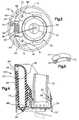
- FIG. 1 is a top view of the nozzle receiving end of the filler tube assembly of the present invention;
- FIG. 2a is a section view taken along
section indicating lines 2a-2a of FIG. 1; - FIG. 2b is a section view taken along
section indicating lines 2b-2b of FIG. 1; - FIG. 3 is a bottom view of the filler tube of FIG. 1;
- FIG. 4 is a section view similar to FIG. 2a of another embodiment of the invention; and,
- FIG. 5 is a perspective view of the plastic baffle insert for the embodiment of FIG. 1.
-
- Referring to FIGS. 1 through 3 and 5, the filler tube assembly of the present invention is indicated generally at 10 and includes a
tubular member 12 having an openupper end 14 and a transverse partition orbulkhead 16 formed therein which has a reduceddiameter aperture 18 disposed therein and has a resilient annular seal indicated generally at 20 provided therein which is operative upon insertion of a refuelingnozzle 22, indicated by dashed outline in FIG. 2b and solid outline in FIG. 4, to seal about the periphery of thenozzle 22. - The resilient
annular seal 20 has abulbous rim portion 26 which is received in anannular groove 28 formed in the lower end of thefiller tube 12 and is radially compressed therein for retaining and sealing theresilient seal 20 in its position thereon. - The
annular seal member 20 has a second sealing surface provided on the lower end thereof in the form of a resilient annular lip orrim flange 30 which extends outwardly radially in a downward direction from thefiller tube 12 and has sealed thereagainst theupper surface 34 of a flapper or trap door indicated generally at 32. Theupper surface 34 is biased against therim flange 30 in sealing engagement by oneend 36 oftorsion spring 38.Spring 38 is received over a shaft orpin 40 anchored inprojections partition 16 of thetube 12. Aspring anchor lug 46 is provided on the undersurface of theflapper 32 against which theend 36 ofspring 38 is registered. Theopposite end 48 of thetorsion spring 38 is registered against another lug orprojection 48 provided on the lower surface of thebulkhead 16. - In the presently preferred practice of the invention, a pressure relief valve 50 is provided in the
flapper 32 to provide emergency relief of any overpressure in the fuel tank which could cause rupture of the tank. The pressure relief valve communicates with the interior of a cup-shaped member 52 disposed over theupper surface 34 of the flapper whichmember 52 has a plurality ofapertures 54 provided therein to permit vapors to escape into the upper region of the filler tube upon opening of the valve 50. It will be understood that the pressure relief valve is biased to the closed position by aspring 56 which provides a preset pressure threshold below which valve 50 remains closed. - Referring to FIG. 3, the
flapper valve 32 has a pair ofarms pin 40 passing therethrough to thereby provide a pivot axis for theflapper 32. - Referring to FIGS. 1, 2a and 2b, the filler tube has formed interiorly thereof a smaller diameter tubular region denoted by
reference numeral 58 which communicates with theaperture 18 for the filler nozzle with thetubular region 58 sized to guide the filler nozzle into theaperture 18. Thefiller tube structure 12 has auxiliary wall portions formed therein which are outside of thetubular region 58 as denoted byreference numerals vent passage interior 58 of the filler tube nozzle region. It will be understood that each of thepassages seal lip 30. The upper end ofpassages tube 12.Wall portions tube 58 form anopen cavity 82. Asuitable baffle cap 74 is disposed over the upper ends of thepassages cap 74 has a pair offluted projections 76, 78 (see FIG. 5) extending therefrom which frictionally interfit the upper ends of thepassages cavity 82.Cap 74 has aflange portion 80 which extends over theopen cavity 82 formed between thepartitions cavity 82. - Each of the
vent passages ports Ports passages cavity 82 which is open to the atmosphere, but baffled byflange 80 ofcap 74. During a refueling event, air is allowed to flow fromcavity 82 throughvent passages filler neck tube 12. - Referring to FIG. 4, an alternate embodiment of the invention is indicated generally at 100 in which the filler tube 12' has a nozzle tube portion 58' of reduced diameter provided with a resilient annular seal 20' with sealing surface 24' for engaging the exterior of the nozzle. A lower-end resilient sealing rim flange 30' is provided upon which is sealed the flapper valve indicated generally at 32'. The flapper 32' is shown in solid outline in the closed position in FIG. 4 and in the open position in dashed outline.
- The vent passages in the
embodiment 100 of FIG. 4 are formed on the interior wall of the tube 12' one of which is shown in FIG. 4 and denoted byreference numeral 70' and has the upper end thereof closed to the interior of the tube 12'. The cross port 84' is formed in the wall of the tube 12' to communicatepassage 70' with the exterior thereof. - With continuing reference to FIG. 4, the lower end of the
vent passage 70' is terminated at generally the same longitudinal station as the end flange seal 30'; and, flapper 32' has provided thereon a pair of resilient auxiliary seal members, one of which is shown in FIG. 4 and denoted by reference numeral 88' and which is disposed over the lower end ofvent passage 70'. It will be understood that similar resilient seals are also provided on theflapper 32 of the embodiment of FIG. 3 and denoted byreference numerals passages - Referring to FIG. 4 in the present practice of the
invention embodiment 100 the auxiliary seal 88' is secured to flapper 32' by aprojection 89 formed thereon which extends through an aperture formed in the flapper 32'. - Similarly with respect to the
embodiment 10 of FIGS. 1 through 3,auxiliary seal 80 is secured toflapper 32 by projection 81 formed thereon extending through the flapper; and,auxiliary seal 90 is secured toflapper 32 by aprojection 91 formed thereon extending through an aperture in theflapper 32. In theembodiment 100 of FIG. 4, the filler tube 12' is shown received in a support tube 92 which has ahole 96 provided therein to permit the vent cross-passage 84' to discharge outside the filler tube. - In operation, both
embodiments nozzle 22 into theseal 20, 20' until the end of the nozzle contacts theflapper 30, 32'; and, upon further insertion by the user thereupon moving the flapper downwardly to the open position shown in dashed outline in FIGS. 2b and 4 opening therim seal 30, 30' and thevent passages - Upon removal of the
nozzle 22auxiliary seal - The present invention thus provides a unique and novel technique for venting and closing a capless fuel tank filler neck by providing auxiliary vent passages disposed in parallel relationship exteriorly of the nozzle receiving tube which vent passages are commonly opened and closed by the nozzle trap door or flapper valve provided in the filler neck.
- Although the invention has hereinabove been described with respect to the illustrated embodiments, it will be understood that the invention is capable of modification and variation and is limited only by the following claims.
Claims (12)
- A filler tube assembly for preventing spray-back during refueling of a vehicle fuel tank comprising:(a) a tube structure defining a fill passage having a first end connected to the fuel tank and a second end opposite said first end open for refueling through an access port on the vehicle;(b) said tube structure also defining a vent passage disposed alongside said filler passage and having a first end communicating with the atmosphere and a second end communicating with said tank;(c) a resilient structure defining a first annular seal in said filler tube, said seal operable, upon insertion of a refueling nozzle in said tube, for sealing about said nozzle, said resilient structure defining a second annular seal disposed along said filler passage between said first seal and said tank;(d) a valve member disposed for movement with respect to said tube structure, said valve member including a first sealing surface operable to seal about said second annular seal and a second sealing surface operable to seal about said second end of said vent passage, wherein upon insertion of said refueling nozzle into said filler passage second end said nozzle initially is sealed about by said first annular seal and upon continued insertion of said nozzle in said filler passage, said valve member is moved progressively to first unseal said second annular seal and then unseal said second end of said vent passage; wherein upon filling of said tank to a full level where fuel enters said vent passage for discharge through said first end of said vent passage, wherein upon withdrawal of said refueling nozzle from said filler passage, said second sealing surface closes second end of said vent passage before said first sealing surface closes said first end of said filler passage.
- The assembly defined in claim 1, wherein said valve member is mounted for pivotal movement on said tube structure.
- The assembly defined in claim 1, wherein said second sealing surface is formed on a resilient sealing member provided on said moveable valve member.
- The assembly defined in claim 1, wherein said second annular seal includes a flexible annular lip.
- The assembly defined in claim 1, further including a plurality of said vent passages with one of said second sealing surface disposed for closing the second end of each of said plurality of vent passages.
- The assembly defined in claim 1, wherein said vent passage is disposed in generally spaced parallel arrangement with said fill passage.
- The assembly defined in claim 1, wherein said first annular seal and said second annular seal are formed integrally in a one piece configuration.
- A method of controlling spray-back during refueling of a vehicle fuel tank from a user operated dispensing nozzle comprising:(a) disposing a first seal in filler tube on the fuel tank and sealing about the dispensing nozzle upon user insertion thereof in the filler tube;(b) disposing a moveable valve member in said filler tube between said first seal and the tank and biasing said valve member to a position closing said filler tube and moving said valve with said nozzle upon further user insertion of said nozzle past said first seal; and,(c) disposing a venting passage communicating the interior of said filler tube with the atmosphere and disposing a seal for closing said vent passage and moving said seal with said valve member upon said further user insertion of said nozzle and opening said vent passage.
- The method defined in claim 8, wherein said step of disposing a valve member includes pivoting said member on said filler tube.
- The method defined in claim 8, wherein said step of disposing a venting passage includes forming a tube having a first passage for said nozzle and a second vent passage in spaced parallel arrangement therewith.
- The method defined in claim 8, wherein said step of disposing a valve member includes disposing an auxiliary pressure relief valve in said moveable valve member.
- The method defined in claim 8, wherein said step of moving said seal member includes closing said vent passage and moving said valve member to the closed position upon user removal of said nozzle from said filler tube.
Applications Claiming Priority (2)
| Application Number | Priority Date | Filing Date | Title |
|---|---|---|---|
| US345232 | 1999-06-30 | ||
| US09/345,232 US6155316A (en) | 1999-06-30 | 1999-06-30 | Capless fuel tank filler assembly |
Publications (3)
| Publication Number | Publication Date |
|---|---|
| EP1065086A2 true EP1065086A2 (en) | 2001-01-03 |
| EP1065086A3 EP1065086A3 (en) | 2002-01-02 |
| EP1065086B1 EP1065086B1 (en) | 2004-02-11 |
Family
ID=23354145
Family Applications (1)
| Application Number | Title | Priority Date | Filing Date |
|---|---|---|---|
| EP00112991A Expired - Lifetime EP1065086B1 (en) | 1999-06-30 | 2000-06-21 | Capless fuel tank filler assembly |
Country Status (13)
| Country | Link |
|---|---|
| US (1) | US6155316A (en) |
| EP (1) | EP1065086B1 (en) |
| JP (1) | JP4775677B2 (en) |
| KR (1) | KR100696559B1 (en) |
| AR (1) | AR025844A1 (en) |
| AT (1) | ATE259308T1 (en) |
| AU (1) | AU759606B2 (en) |
| BR (1) | BR0002833A (en) |
| CA (1) | CA2310394C (en) |
| CO (1) | CO5271749A1 (en) |
| DE (1) | DE60008169T2 (en) |
| ES (1) | ES2213520T3 (en) |
| TW (1) | TW448111B (en) |
Cited By (3)
| Publication number | Priority date | Publication date | Assignee | Title |
|---|---|---|---|---|
| WO2006077491A1 (en) * | 2005-01-21 | 2006-07-27 | Eaton Corporation | Capless filler neck assembly for a fuel tank |
| CN1815594B (en) * | 2005-01-31 | 2010-06-09 | 坦德伯格数据有限公司 | Upgradable and expandable unit for data storage systems |
| WO2016060984A1 (en) * | 2014-10-13 | 2016-04-21 | Srg Global, Inc. | Vehicle fuel filler system seal |
Families Citing this family (40)
| Publication number | Priority date | Publication date | Assignee | Title |
|---|---|---|---|---|
| DE10040310C2 (en) * | 2000-08-17 | 2002-11-21 | Alfmeier Praez Ag | Level control valve |
| US6539990B1 (en) | 2001-11-20 | 2003-04-01 | Illinois Tool Works Inc. | Capless refueling assembly |
| US6648016B2 (en) | 2002-01-24 | 2003-11-18 | Alfmeier Corporation | Valve assembly for a fuel tank |
| US6722407B2 (en) | 2002-08-07 | 2004-04-20 | Daimlerchrysler Corporation | Capless fuel refilling system |
| US6926047B1 (en) * | 2002-12-17 | 2005-08-09 | Paraphase, Inc. | Vehicle fuel intake device |
| US20060213576A1 (en) * | 2002-12-17 | 2006-09-28 | Paraphase, Inc. | Replacement vehicle fuel intake device |
| US7080671B2 (en) * | 2002-12-17 | 2006-07-25 | Paraphase, Inc. | Replacement vehicle fuel intake device |
| DE10307355B4 (en) * | 2003-02-21 | 2006-02-09 | Itw Automotive Products Gmbh & Co. Kg | Closing device for a filler pipe of an automotive tank |
| US6932100B2 (en) * | 2003-05-23 | 2005-08-23 | Eaton Corporation | Flapper type fill tube check valve |
| US6880594B1 (en) * | 2004-03-19 | 2005-04-19 | Eaton Corporation | Method and arrangement for sealing a capless fuel tank filler tube |
| US6968874B1 (en) | 2004-10-07 | 2005-11-29 | Martinrea Industries, Inc. | Capless automotive fueling system |
| US7163037B2 (en) * | 2005-01-21 | 2007-01-16 | Eaton Corporation | Guiding movement of capless filler neck closure |
| DE102005004551A1 (en) * | 2005-01-31 | 2006-08-10 | Kautex Textron Gmbh & Co. Kg | outlet connection |
| US7147019B2 (en) * | 2005-01-31 | 2006-12-12 | Eaton Corporation | Filler neck cover |
| US7165583B1 (en) | 2005-01-31 | 2007-01-23 | Eaton Corporation | Door latch for capless filler neck |
| US7055560B1 (en) | 2005-04-18 | 2006-06-06 | Gaton Corporation | Cover for capless filler tube |
| US7007726B1 (en) | 2005-04-18 | 2006-03-07 | Eaton Corporation | Cover closure assembly and method for fuel tank filler |
| DE112006000847T5 (en) * | 2005-04-19 | 2008-03-06 | Eaton Corp., Cleveland | Coverless closure assembly for a fuel tank filler neck and method for capless closure thereof |
| WO2008013325A1 (en) | 2006-07-28 | 2008-01-31 | Toyoda Gosei Co., Ltd. | Opening/closing device for tank |
| JP4760616B2 (en) * | 2006-08-30 | 2011-08-31 | 豊田合成株式会社 | Tank opening and closing device |
| AT9945U1 (en) * | 2007-03-27 | 2008-06-15 | Magna Steyr Fuel Systems Gesmb | FILLING IN A FUEL TANK WITH PROTECTION BEFORE FAILING |
| JP2009061974A (en) * | 2007-09-07 | 2009-03-26 | Honda Motor Co Ltd | Fuel lid structure |
| JP4379518B2 (en) * | 2007-11-29 | 2009-12-09 | トヨタ自動車株式会社 | Fuel tank fueling part structure |
| US20090139606A1 (en) * | 2007-11-30 | 2009-06-04 | Parker-Hannifin Corporation | Contoured door with seal |
| US20090145899A1 (en) * | 2007-12-07 | 2009-06-11 | Eaton Corporation | Capless refueling system cover with locking mechanism |
| US20100193076A1 (en) * | 2009-01-30 | 2010-08-05 | Walkowski Paul D | Capless fuel tank filler pipe assembly |
| DE102009010406B4 (en) * | 2009-02-26 | 2011-09-22 | Magna Steyr Fuel Systems Gesmbh | Filling head for a fuel tank with a protective device |
| US8413431B2 (en) * | 2009-06-30 | 2013-04-09 | Eaton Corporation | Tank assembly |
| KR101191747B1 (en) | 2010-07-19 | 2012-10-15 | 코리아에프티 주식회사 | Capless filler tube assembly for car |
| EP2679428B1 (en) * | 2011-02-23 | 2017-11-15 | Toyota Jidosha Kabushiki Kaisha | Fuel tank fuel filler structure |
| US10000117B2 (en) | 2012-02-17 | 2018-06-19 | Stant Usa Corp. | Filler neck closure assembly |
| JP6029423B2 (en) * | 2012-11-09 | 2016-11-24 | 株式会社キーレックス | Fuel filler pipe fuel filler structure |
| US9296292B2 (en) | 2013-12-09 | 2016-03-29 | Martinrea Industries, Inc. | Capless fuel system |
| KR101481343B1 (en) * | 2013-12-10 | 2015-01-09 | 현대자동차주식회사 | Misfuelling prevention system for vehicles |
| JP6150772B2 (en) | 2014-08-26 | 2017-06-21 | 株式会社ニフコ | Check valve for fuel tank |
| US9944171B2 (en) * | 2015-01-30 | 2018-04-17 | Martinrea Industries, Inc. | Capless automotive fueling system with miss-fuel inhibitor |
| JP6406055B2 (en) * | 2015-02-26 | 2018-10-17 | 豊田合成株式会社 | Flap valve mechanism |
| DE102016002045B4 (en) | 2015-02-26 | 2022-04-14 | Toyoda Gosei Co., Ltd. | Opening-closing device for a fuel tank |
| US10675970B2 (en) * | 2016-08-15 | 2020-06-09 | Ford Global Technologies, Llc | Vehicle capless refueling system |
| DE202022100364U1 (en) * | 2021-02-04 | 2022-05-25 | Stant Usa Corp. | Capless cap assembly for fuel tank filler neck |
Family Cites Families (12)
| Publication number | Priority date | Publication date | Assignee | Title |
|---|---|---|---|---|
| DE2950640C2 (en) * | 1979-12-15 | 1981-11-12 | Adam Opel AG, 6090 Rüsselsheim | Fuel tank with fuel filler pipe, in particular for motor vehicles |
| JPH0342719U (en) * | 1989-08-29 | 1991-04-23 | ||
| JP2519041Y2 (en) * | 1990-12-27 | 1996-12-04 | エヌオーケー株式会社 | Sealing device for fuel tank filling port |
| JP2520438Y2 (en) * | 1991-07-19 | 1996-12-18 | エヌオーケー株式会社 | Oil filler seal device |
| JPH0589059U (en) * | 1992-05-08 | 1993-12-03 | 本田技研工業株式会社 | Fuel tank injection pipe device |
| FR2693957B1 (en) * | 1992-07-27 | 1994-10-14 | Renault | Fuel tank filler pipe. |
| US5431199A (en) * | 1993-11-30 | 1995-07-11 | Benjey, Robert P | Redundant seal for vehicle filler neck |
| AT403141B (en) * | 1995-09-19 | 1997-11-25 | Blau Automobiltechnik Gmbh | LOCKING DEVICE FOR A VEHICLE TANK FILLER |
| KR970030658U (en) * | 1995-12-31 | 1997-07-24 | Internal structure of fuel injection port for automobile | |
| DE19714813C1 (en) * | 1997-04-10 | 1998-07-23 | Freudenberg Carl Fa | Fuel tank with filling connection and storage chamber for fuel vapour |
| CA2296528C (en) * | 1997-07-17 | 2006-11-28 | Tesma International Inc. | Capless refueling assembly |
| US5960839A (en) * | 1998-08-05 | 1999-10-05 | Ford Global Technologies, Inc. | Fuel tank system |
-
1999
- 1999-06-30 US US09/345,232 patent/US6155316A/en not_active Expired - Fee Related
-
2000
- 2000-05-25 TW TW089110121A patent/TW448111B/en not_active IP Right Cessation
- 2000-06-01 CA CA002310394A patent/CA2310394C/en not_active Expired - Fee Related
- 2000-06-21 AR ARP000103068A patent/AR025844A1/en active IP Right Grant
- 2000-06-21 AT AT00112991T patent/ATE259308T1/en not_active IP Right Cessation
- 2000-06-21 DE DE60008169T patent/DE60008169T2/en not_active Expired - Lifetime
- 2000-06-21 ES ES00112991T patent/ES2213520T3/en not_active Expired - Lifetime
- 2000-06-21 EP EP00112991A patent/EP1065086B1/en not_active Expired - Lifetime
- 2000-06-23 JP JP2000189215A patent/JP4775677B2/en not_active Expired - Fee Related
- 2000-06-27 BR BR0002833-9A patent/BR0002833A/en active Search and Examination
- 2000-06-27 KR KR1020000035527A patent/KR100696559B1/en not_active Expired - Fee Related
- 2000-06-28 AU AU42727/00A patent/AU759606B2/en not_active Ceased
- 2000-06-29 CO CO00048971A patent/CO5271749A1/en not_active Application Discontinuation
Non-Patent Citations (1)
| Title |
|---|
| None |
Cited By (6)
| Publication number | Priority date | Publication date | Assignee | Title |
|---|---|---|---|---|
| WO2006077491A1 (en) * | 2005-01-21 | 2006-07-27 | Eaton Corporation | Capless filler neck assembly for a fuel tank |
| US7306017B2 (en) | 2005-01-21 | 2007-12-11 | Eaton Corporation | Capless filler neck assembly for a fuel tank |
| CN1815594B (en) * | 2005-01-31 | 2010-06-09 | 坦德伯格数据有限公司 | Upgradable and expandable unit for data storage systems |
| WO2016060984A1 (en) * | 2014-10-13 | 2016-04-21 | Srg Global, Inc. | Vehicle fuel filler system seal |
| US9376012B2 (en) | 2014-10-13 | 2016-06-28 | Srg Global, Inc. | Vehicle fuel filler system seal |
| US9862266B2 (en) | 2014-10-13 | 2018-01-09 | Srg Global, Inc. | Vehicle fuel filler system seal |
Also Published As
| Publication number | Publication date |
|---|---|
| AU4272700A (en) | 2001-01-04 |
| JP4775677B2 (en) | 2011-09-21 |
| ATE259308T1 (en) | 2004-02-15 |
| TW448111B (en) | 2001-08-01 |
| CA2310394C (en) | 2005-11-08 |
| US6155316A (en) | 2000-12-05 |
| EP1065086A3 (en) | 2002-01-02 |
| KR20010007533A (en) | 2001-01-26 |
| DE60008169D1 (en) | 2004-03-18 |
| CO5271749A1 (en) | 2003-04-30 |
| AR025844A1 (en) | 2002-12-18 |
| DE60008169T2 (en) | 2004-09-16 |
| KR100696559B1 (en) | 2007-03-19 |
| EP1065086B1 (en) | 2004-02-11 |
| AU759606B2 (en) | 2003-04-17 |
| JP2001047876A (en) | 2001-02-20 |
| BR0002833A (en) | 2002-05-14 |
| CA2310394A1 (en) | 2000-12-30 |
| ES2213520T3 (en) | 2004-09-01 |
Similar Documents
| Publication | Publication Date | Title |
|---|---|---|
| EP1065086B1 (en) | Capless fuel tank filler assembly | |
| US6691750B1 (en) | Floating nozzle collar for capless filler neck | |
| US6561211B2 (en) | Fuel tank vent control valve | |
| US4790349A (en) | Tank pressure control system | |
| US4091959A (en) | Gas cap | |
| US6918405B2 (en) | Fill limit vent valve | |
| US5044389A (en) | High volume fuel vapor release valve | |
| US4991615A (en) | Tank pressure control apparatus | |
| US5195566A (en) | Cap for the filler neck of liquid containers | |
| US5261439A (en) | Vacuum-actuated vent assembly | |
| US4630749A (en) | Fuel fill tube with vapor vent and overfill protection | |
| EP0437053A1 (en) | Non-expulsive fuel filler assembly | |
| US7882862B2 (en) | Fuel and vapor vent management system for filler neck | |
| US5782262A (en) | Gas ventilation apparatus for a fuel tank | |
| US6848463B2 (en) | Vapor vent valve | |
| JPH06156093A (en) | Fuel cut-off valve with float | |
| JPH09126078A (en) | Control valve and device for fuel vapor recovery | |
| US7234452B2 (en) | Controlling vapor emission in a small engine fuel tank system | |
| KR20030086413A (en) | Method of venting fuel vapor from a tank and system therefor | |
| US7287542B2 (en) | Shutoff valve for mechanically sealed ORVR system | |
| US20020112757A1 (en) | Easy opening fuel tank vent valve | |
| JP3337183B2 (en) | Stop valve structure | |
| US5775392A (en) | Motor vehicle tank with filling tube vent | |
| MXPA00006460A (en) | Capless fuel tank filler assembly | |
| JP3036942B2 (en) | Fuel tank evaporative fuel treatment system |
Legal Events
| Date | Code | Title | Description |
|---|---|---|---|
| EUG | Se: european patent has lapsed | ||
| PUAI | Public reference made under article 153(3) epc to a published international application that has entered the european phase |
Free format text: ORIGINAL CODE: 0009012 |
|
| AK | Designated contracting states |
Kind code of ref document: A2 Designated state(s): AT BE CH CY DE DK ES FI FR GB GR IE IT LI LU MC NL PT SE |
|
| AX | Request for extension of the european patent |
Free format text: AL;LT;LV;MK;RO;SI |
|
| PUAL | Search report despatched |
Free format text: ORIGINAL CODE: 0009013 |
|
| AK | Designated contracting states |
Kind code of ref document: A3 Designated state(s): AT BE CH CY DE DK ES FI FR GB GR IE IT LI LU MC NL PT SE |
|
| AX | Request for extension of the european patent |
Free format text: AL;LT;LV;MK;RO;SI |
|
| 17P | Request for examination filed |
Effective date: 20020419 |
|
| AKX | Designation fees paid |
Free format text: AT BE CH CY DE DK ES FI FR GB GR IE IT LI LU MC NL PT SE |
|
| GRAP | Despatch of communication of intention to grant a patent |
Free format text: ORIGINAL CODE: EPIDOSNIGR1 |
|
| GRAS | Grant fee paid |
Free format text: ORIGINAL CODE: EPIDOSNIGR3 |
|
| GRAA | (expected) grant |
Free format text: ORIGINAL CODE: 0009210 |
|
| AK | Designated contracting states |
Kind code of ref document: B1 Designated state(s): AT BE CH CY DE DK ES FI FR GB GR IE IT LI LU MC NL PT SE |
|
| PG25 | Lapsed in a contracting state [announced via postgrant information from national office to epo] |
Ref country code: LI Free format text: LAPSE BECAUSE OF FAILURE TO SUBMIT A TRANSLATION OF THE DESCRIPTION OR TO PAY THE FEE WITHIN THE PRESCRIBED TIME-LIMIT Effective date: 20040211 Ref country code: BE Free format text: LAPSE BECAUSE OF FAILURE TO SUBMIT A TRANSLATION OF THE DESCRIPTION OR TO PAY THE FEE WITHIN THE PRESCRIBED TIME-LIMIT Effective date: 20040211 Ref country code: FI Free format text: LAPSE BECAUSE OF FAILURE TO SUBMIT A TRANSLATION OF THE DESCRIPTION OR TO PAY THE FEE WITHIN THE PRESCRIBED TIME-LIMIT Effective date: 20040211 Ref country code: CH Free format text: LAPSE BECAUSE OF FAILURE TO SUBMIT A TRANSLATION OF THE DESCRIPTION OR TO PAY THE FEE WITHIN THE PRESCRIBED TIME-LIMIT Effective date: 20040211 Ref country code: AT Free format text: LAPSE BECAUSE OF FAILURE TO SUBMIT A TRANSLATION OF THE DESCRIPTION OR TO PAY THE FEE WITHIN THE PRESCRIBED TIME-LIMIT Effective date: 20040211 Ref country code: CY Free format text: LAPSE BECAUSE OF FAILURE TO SUBMIT A TRANSLATION OF THE DESCRIPTION OR TO PAY THE FEE WITHIN THE PRESCRIBED TIME-LIMIT Effective date: 20040211 |
|
| REG | Reference to a national code |
Ref country code: GB Ref legal event code: FG4D |
|
| REG | Reference to a national code |
Ref country code: CH Ref legal event code: EP |
|
| REG | Reference to a national code |
Ref country code: IE Ref legal event code: FG4D |
|
| REF | Corresponds to: |
Ref document number: 60008169 Country of ref document: DE Date of ref document: 20040318 Kind code of ref document: P |
|
| PG25 | Lapsed in a contracting state [announced via postgrant information from national office to epo] |
Ref country code: GR Free format text: LAPSE BECAUSE OF FAILURE TO SUBMIT A TRANSLATION OF THE DESCRIPTION OR TO PAY THE FEE WITHIN THE PRESCRIBED TIME-LIMIT Effective date: 20040511 Ref country code: DK Free format text: LAPSE BECAUSE OF FAILURE TO SUBMIT A TRANSLATION OF THE DESCRIPTION OR TO PAY THE FEE WITHIN THE PRESCRIBED TIME-LIMIT Effective date: 20040511 |
|
| PG25 | Lapsed in a contracting state [announced via postgrant information from national office to epo] |
Ref country code: LU Free format text: LAPSE BECAUSE OF NON-PAYMENT OF DUE FEES Effective date: 20040621 Ref country code: IE Free format text: LAPSE BECAUSE OF NON-PAYMENT OF DUE FEES Effective date: 20040621 |
|
| PG25 | Lapsed in a contracting state [announced via postgrant information from national office to epo] |
Ref country code: MC Free format text: LAPSE BECAUSE OF NON-PAYMENT OF DUE FEES Effective date: 20040630 |
|
| REG | Reference to a national code |
Ref country code: CH Ref legal event code: PL |
|
| REG | Reference to a national code |
Ref country code: ES Ref legal event code: FG2A Ref document number: 2213520 Country of ref document: ES Kind code of ref document: T3 |
|
| ET | Fr: translation filed | ||
| PLBE | No opposition filed within time limit |
Free format text: ORIGINAL CODE: 0009261 |
|
| STAA | Information on the status of an ep patent application or granted ep patent |
Free format text: STATUS: NO OPPOSITION FILED WITHIN TIME LIMIT |
|
| 26N | No opposition filed |
Effective date: 20041112 |
|
| REG | Reference to a national code |
Ref country code: IE Ref legal event code: MM4A |
|
| PGFP | Annual fee paid to national office [announced via postgrant information from national office to epo] |
Ref country code: GB Payment date: 20060505 Year of fee payment: 7 |
|
| PGFP | Annual fee paid to national office [announced via postgrant information from national office to epo] |
Ref country code: NL Payment date: 20060508 Year of fee payment: 7 |
|
| PGFP | Annual fee paid to national office [announced via postgrant information from national office to epo] |
Ref country code: SE Payment date: 20060602 Year of fee payment: 7 |
|
| PGFP | Annual fee paid to national office [announced via postgrant information from national office to epo] |
Ref country code: FR Payment date: 20060605 Year of fee payment: 7 |
|
| PGFP | Annual fee paid to national office [announced via postgrant information from national office to epo] |
Ref country code: ES Payment date: 20060622 Year of fee payment: 7 |
|
| PGFP | Annual fee paid to national office [announced via postgrant information from national office to epo] |
Ref country code: IT Payment date: 20060630 Year of fee payment: 7 |
|
| PG25 | Lapsed in a contracting state [announced via postgrant information from national office to epo] |
Ref country code: PT Free format text: LAPSE BECAUSE OF NON-PAYMENT OF DUE FEES Effective date: 20040711 |
|
| EUG | Se: european patent has lapsed | ||
| GBPC | Gb: european patent ceased through non-payment of renewal fee |
Effective date: 20070621 |
|
| NLV4 | Nl: lapsed or anulled due to non-payment of the annual fee |
Effective date: 20080101 |
|
| REG | Reference to a national code |
Ref country code: FR Ref legal event code: ST Effective date: 20080229 |
|
| PG25 | Lapsed in a contracting state [announced via postgrant information from national office to epo] |
Ref country code: NL Free format text: LAPSE BECAUSE OF NON-PAYMENT OF DUE FEES Effective date: 20080101 |
|
| PG25 | Lapsed in a contracting state [announced via postgrant information from national office to epo] |
Ref country code: GB Free format text: LAPSE BECAUSE OF NON-PAYMENT OF DUE FEES Effective date: 20070621 |
|
| PG25 | Lapsed in a contracting state [announced via postgrant information from national office to epo] |
Ref country code: SE Free format text: LAPSE BECAUSE OF NON-PAYMENT OF DUE FEES Effective date: 20070622 |
|
| REG | Reference to a national code |
Ref country code: ES Ref legal event code: FD2A Effective date: 20070622 |
|
| PG25 | Lapsed in a contracting state [announced via postgrant information from national office to epo] |
Ref country code: FR Free format text: LAPSE BECAUSE OF NON-PAYMENT OF DUE FEES Effective date: 20070702 |
|
| PG25 | Lapsed in a contracting state [announced via postgrant information from national office to epo] |
Ref country code: ES Free format text: LAPSE BECAUSE OF NON-PAYMENT OF DUE FEES Effective date: 20070622 |
|
| PG25 | Lapsed in a contracting state [announced via postgrant information from national office to epo] |
Ref country code: IT Free format text: LAPSE BECAUSE OF NON-PAYMENT OF DUE FEES Effective date: 20070621 |
|
| PGFP | Annual fee paid to national office [announced via postgrant information from national office to epo] |
Ref country code: DE Payment date: 20110630 Year of fee payment: 12 |
|
| REG | Reference to a national code |
Ref country code: DE Ref legal event code: R119 Ref document number: 60008169 Country of ref document: DE Effective date: 20130101 |
|
| PG25 | Lapsed in a contracting state [announced via postgrant information from national office to epo] |
Ref country code: DE Free format text: LAPSE BECAUSE OF NON-PAYMENT OF DUE FEES Effective date: 20130101 |