EP1065076A1 - Tire air pressure estimating device - Google Patents
Tire air pressure estimating device Download PDFInfo
- Publication number
- EP1065076A1 EP1065076A1 EP00114251A EP00114251A EP1065076A1 EP 1065076 A1 EP1065076 A1 EP 1065076A1 EP 00114251 A EP00114251 A EP 00114251A EP 00114251 A EP00114251 A EP 00114251A EP 1065076 A1 EP1065076 A1 EP 1065076A1
- Authority
- EP
- European Patent Office
- Prior art keywords
- air pressure
- tire
- wheel rotation
- rotation sensor
- vibration
- Prior art date
- Legal status (The legal status is an assumption and is not a legal conclusion. Google has not performed a legal analysis and makes no representation as to the accuracy of the status listed.)
- Withdrawn
Links
- 230000008859 change Effects 0.000 claims description 38
- 230000007423 decrease Effects 0.000 claims description 32
- 230000001133 acceleration Effects 0.000 claims description 30
- 238000000034 method Methods 0.000 claims description 30
- 230000004907 flux Effects 0.000 claims description 21
- 238000001514 detection method Methods 0.000 claims description 16
- 238000012937 correction Methods 0.000 claims description 13
- 238000006073 displacement reaction Methods 0.000 claims description 11
- 239000000725 suspension Substances 0.000 claims description 10
- 230000008569 process Effects 0.000 claims description 8
- 238000005452 bending Methods 0.000 claims description 6
- 238000000605 extraction Methods 0.000 claims description 4
- 230000000630 rising effect Effects 0.000 claims description 4
- 230000015572 biosynthetic process Effects 0.000 claims description 3
- 238000003786 synthesis reaction Methods 0.000 claims description 3
- 238000012545 processing Methods 0.000 abstract description 29
- 238000010586 diagram Methods 0.000 description 95
- 238000001228 spectrum Methods 0.000 description 27
- 230000000694 effects Effects 0.000 description 10
- 238000009434 installation Methods 0.000 description 10
- 230000001419 dependent effect Effects 0.000 description 7
- 230000006399 behavior Effects 0.000 description 6
- 230000003247 decreasing effect Effects 0.000 description 6
- 238000005259 measurement Methods 0.000 description 5
- 239000013598 vector Substances 0.000 description 5
- 150000001875 compounds Chemical class 0.000 description 3
- 230000005489 elastic deformation Effects 0.000 description 3
- 230000008030 elimination Effects 0.000 description 3
- 238000003379 elimination reaction Methods 0.000 description 3
- 230000007246 mechanism Effects 0.000 description 2
- 238000012544 monitoring process Methods 0.000 description 2
- 239000011347 resin Substances 0.000 description 2
- 229920005989 resin Polymers 0.000 description 2
- 230000035945 sensitivity Effects 0.000 description 2
- 238000012546 transfer Methods 0.000 description 2
- 230000002542 deteriorative effect Effects 0.000 description 1
- 229910052737 gold Inorganic materials 0.000 description 1
- 230000006872 improvement Effects 0.000 description 1
- 230000005389 magnetism Effects 0.000 description 1
- 239000000463 material Substances 0.000 description 1
- 239000002184 metal Substances 0.000 description 1
- 229910052751 metal Inorganic materials 0.000 description 1
- 238000012986 modification Methods 0.000 description 1
- 230000004048 modification Effects 0.000 description 1
- 230000010363 phase shift Effects 0.000 description 1
- 230000000644 propagated effect Effects 0.000 description 1
- 238000011160 research Methods 0.000 description 1
- 238000000926 separation method Methods 0.000 description 1
- 238000007493 shaping process Methods 0.000 description 1
- 230000002194 synthesizing effect Effects 0.000 description 1
Images










Classifications
-
- B—PERFORMING OPERATIONS; TRANSPORTING
- B60—VEHICLES IN GENERAL
- B60C—VEHICLE TYRES; TYRE INFLATION; TYRE CHANGING; CONNECTING VALVES TO INFLATABLE ELASTIC BODIES IN GENERAL; DEVICES OR ARRANGEMENTS RELATED TO TYRES
- B60C23/00—Devices for measuring, signalling, controlling, or distributing tyre pressure or temperature, specially adapted for mounting on vehicles; Arrangement of tyre inflating devices on vehicles, e.g. of pumps or of tanks; Tyre cooling arrangements
- B60C23/06—Signalling devices actuated by deformation of the tyre, e.g. tyre mounted deformation sensors or indirect determination of tyre deformation based on wheel speed, wheel-centre to ground distance or inclination of wheel axle
- B60C23/061—Signalling devices actuated by deformation of the tyre, e.g. tyre mounted deformation sensors or indirect determination of tyre deformation based on wheel speed, wheel-centre to ground distance or inclination of wheel axle by monitoring wheel speed
- B60C23/062—Frequency spectrum analysis of wheel speed signals, e.g. using Fourier transformation
-
- B—PERFORMING OPERATIONS; TRANSPORTING
- B60—VEHICLES IN GENERAL
- B60C—VEHICLE TYRES; TYRE INFLATION; TYRE CHANGING; CONNECTING VALVES TO INFLATABLE ELASTIC BODIES IN GENERAL; DEVICES OR ARRANGEMENTS RELATED TO TYRES
- B60C23/00—Devices for measuring, signalling, controlling, or distributing tyre pressure or temperature, specially adapted for mounting on vehicles; Arrangement of tyre inflating devices on vehicles, e.g. of pumps or of tanks; Tyre cooling arrangements
- B60C23/06—Signalling devices actuated by deformation of the tyre, e.g. tyre mounted deformation sensors or indirect determination of tyre deformation based on wheel speed, wheel-centre to ground distance or inclination of wheel axle
-
- B—PERFORMING OPERATIONS; TRANSPORTING
- B60—VEHICLES IN GENERAL
- B60C—VEHICLE TYRES; TYRE INFLATION; TYRE CHANGING; CONNECTING VALVES TO INFLATABLE ELASTIC BODIES IN GENERAL; DEVICES OR ARRANGEMENTS RELATED TO TYRES
- B60C23/00—Devices for measuring, signalling, controlling, or distributing tyre pressure or temperature, specially adapted for mounting on vehicles; Arrangement of tyre inflating devices on vehicles, e.g. of pumps or of tanks; Tyre cooling arrangements
- B60C23/06—Signalling devices actuated by deformation of the tyre, e.g. tyre mounted deformation sensors or indirect determination of tyre deformation based on wheel speed, wheel-centre to ground distance or inclination of wheel axle
- B60C23/061—Signalling devices actuated by deformation of the tyre, e.g. tyre mounted deformation sensors or indirect determination of tyre deformation based on wheel speed, wheel-centre to ground distance or inclination of wheel axle by monitoring wheel speed
Definitions
- the present invention relates to a tire air pressure estimating device for indirectly estimating the air pressure of a tire by carrying out a frequency analysis on a signal generated by typically a wheel speed sensor. More particularly, the present invention relates to improvement of an S/N ratio of the signal generated by the wheel speed sensor by substantially eliminating noise included in the signal in indirect estimation of the air pressure of the tire.
- a tire air pressure estimating device whereby variations in rotational speed dependent on the air pressure of a wheel tire are detected by carrying out a frequency analysis on a signal generated by typically a wheel speed sensor as is disclosed for example in JP-A-No. H5-133831.
- a signal generated by a wheel speed sensor for an antilock brake system (ABS) is supplied to an electronic control unit (ECU) as pulses through an ordinary wave shaping circuit to be recognized by the ECU.
- the pulses are used as a base for reproducing the original analog waveform from which the rotational speed of the wheel is found.
- a resonance frequency dependent on a spring constant of the tire is directly found by applying an FFT (Fast Fourier Transform) technique or a linear estimation technique to the rotational speed of the wheel reproduced by approximation.
- FFT Fast Fourier Transform
- variations in resonance frequency are indirectly found. Such variations are dependent on a spring constant of the tire which is found as an estimated value by applying a disturbance observer technique or the like.
- the resonance frequency dependent on the air pressure of the tire or an equivalent quantity of the resonance frequency is computed to find the current air pressure of the tire which is then compared with the normal air pressure of the tire obtained at an initial time. If the result of the comparison indicates a decrease in tire air pressure, a warning is given to the driver.
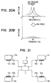
- a decrease in tire air pressure is detected as a change in a resonance frequency of a tire spring unit from about 40 Hz as indicated by a shift from a solid line to a dashed line shown in Fig. 20A and 20B. Such a decrease can then be used to estimate the air pressure of the tire itself.
- the gain of the frequency spectrum of an observed signal is large as shown in Fig. 20A. In this case, a change in air pressure of the tire can be estimated satisfactorily from a variation in resonance frequency.
- the gain of the frequency spectrum of the observed signal is small as shown in Fig. 20B. In this case, it is quite within the bounds of possibility that the air pressure of the tire is difficult to estimate particularly at a high vehicle speed.
- the wheel speed sensor used in such a tire air pressure estimating device is provided on an axle housing of the vehicle. Attached to lower and upper arms, the axle housing experiences propagation of a vibration of a propeller shaft, a drive shaft and a differential.
- the wheel speed sensor is installed to face a rotor which exhibits projections or has slits on the circumferential surface thereof.
- the rotor is attached to an axle or a member which rotates along with the axle.
- the axle housing thus vibrates in accordance with a vibration of an unsprung which is inherent in the vehicle and accompanies a suspension vibration and the like. Accordingly, the wheel speed sensor itself also vibrates inevitably in accordance with the vibration of the unsprung.
- the vibration of the wheel speed sensor itself appears as noise in a signal generated by the sensor, raising a problem of a decreased S/N ratio of the signal.
- the present invention provides a tire air pressure estimating device for estimating the air pressure of a tire or detecting a change in air pressure of the tire by utilizing eccentricity of the shaft center of a wheel.
- the eccentricity of the shaft center of a wheel vibrates at a large amplitude.
- the tire pressure estimating device implements estimation of the air pressure of a tire or detection of a change in air pressure of the tire based on a relation between a vibration component caused by eccentricity and the air pressure of the tire.
- the vibration component caused by the eccentricity of an axle can be extracted by carrying out a frequency analysis on a signal generated by a wheel speed sensor, or by observing a force applied to an axle, a displacement or an acceleration of the axle or a phenomenon which represents the force, the displacement or the acceleration and occurs in the structure of the axle itself or a structure surrounding the axle.
- the present invention provides: a waviness-component extraction means for extracting a waviness component of a vibration of a signal generated by the wheel speed sensor; and a component separation means for separating noise included in a signal output due to a rotational vibration of the wheel speed sensor itself from the signal.
- two wheel speed sensors facing each other are provided on an axle housing serving as a place for installing wheel speed sensors.
- the air pressure of the tire is then found from a value of synthesis of signals output by the two wheel rotation sensors.
- a rotational vibration noise component included in a signal generated by one of the two wheel rotation sensors cancels a rotational vibration noise component included in a signal generated by the other wheel rotation sensor because of the same phase.
- an eccentricity component output as a signal by one of the two wheel rotation sensors enforces an eccentricity component output as a signal by the other wheel rotation sensor due to their more or less mutually opposite phases. As a result, the magnitude of the output eccentricity component is doubled to give an improved S/N ratio.
- a vibration detection sensor for detecting a vibration of an unsprung of the vehicle
- a noise-component estimating means for estimating a noise component caused by a vibration of a wheel rotation sensor itself at the position of the wheel rotation sensor from a signal generated by the vibration detection sensor
- a noise correction means for adding the noised component estimated by the noise-component estimating means to a signal generated by the wheel rotation. sensor.
- a noise a vibration component at the position of the wheel rotation sensor is estimated from a noise component at the position of the wheel rotation sensor, and a noise component included in a signal generated by the wheel rotation sensor and caused by a rotational vibration of the wheel rotation sensor can be eliminated in a time or frequency domain.
- an axle on which a rotor of a wheel rotation sensor provided is magnetized so that a variation in magnetic flux caused by eccentricity of the rotor relative to the wheel rotation sensor is magnified by a magnetic flux of an axle and the behavior of an output signal is thus increased in comparison with a noise component.
- the S/N ratio of a signal generated by the wheel rotation sensor is improved.
- a signal component in a radial component of a rotor which is installed to face a wheel rotation sensor and rotates along with an axle, is increased in a signal generated by the wheel rotation sensor in estimation of the air pressure of a tire by detecting the signal generated by the wheel rotation sensor.
- the air pressure of the tire is estimated by extracting a vibration component attributed by a spring constant of the tire from the signal generated by the wheel rotation sensor and computing the resonance frequency of the tire.
- the vibration component attributed by a spring constant of the tire is a vibration component in the radial direction of the rotor as represented by the forward/backward directions or the upward/downward directions of the wheel.
- a vibration component caused by a vibration of the wheel rotation sensor itself in the rotational direction of the rotor due to suspension a vibration or the like becomes noise in the estimation of the air pressure of the tire.
- the vibration in the radial direction of the rotor in the signal generated by the wheel rotation sensor is increased, the component used in the estimation of the air pressure of the tire is magnified rather than the noise component of the signal generated by the wheel rotation sensor is. As a result, the S/N ratio is raised.
- the vibration in the radial direction of the rotor that is, a vibration component depending on a spring constant of the tire, can be increased with ease.
- a permanent magnet on the wheel rotation sensor can also be vibrated.
- a magnetic vibration system having a permanent magnet movable in the radial direction of the rotor at a location in close proximity to the wheel rotation sensor.
- a wheel rotation sensor is provided at a position in close proximity to a virtual center of rotation of the axle housing by consideration of the phases and the amplitudes of support points for an arm on the vehicle-body side of the axle housing.
- a locus of a rotational vibration of the axle housing can be predicted. If the wheel rotation sensor is installed at a position with a minimum amplitude of the a rotational vibration of the axle housing, that is, if the wheel rotation sensor is installed at the rotational center of the axle housing, the magnitude of a vibration propagated to the wheel rotation sensor can be reduced to a minimum and the amount of noise included in a signal output by the wheel rotation sensor can be decreased most.
- a vibration of a driving system comprising a propeller shaft, a drive shaft, an axle housing and a differential is detected, and a vibration component becoming noise in the estimation of the air pressure of the tire in the vibration is identified.
- the air pressure of the tire can be estimated by taking the noise component into account.
- the precision of the air pressure estimation can be improved.
- an acceleration sensor can be used for detecting a vibration of the driving system. Furthermore, by using an acceleration sensor employed in another device such as an anti-skid device or a car-body behavior control device as the acceleration sensor for detecting a vibration of the driving system, a cost increase caused by the use of a tire air pressure estimating device in a vehicle can be reduced considerably. It should be noted that there are many types of car in which the acceleration sensor used in another device such as an anti-skid device or a car-body behavior control device is installed on a mount portion of the differential so that the vibration of the driving system can be detected as a vibration at a position in close proximity to the mount portion of the differential. Thus, the use of the acceleration sensor employed in such another device as the acceleration sensor for the tire air pressure estimating device is very suitable.
- a first embodiment of the present invention is explained by referring to diagrams as follows.
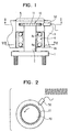
- Fig. 1 is a diagram showing the periphery of the shaft of a wheel employed in a vehicle having an ABS device.
- a tire (not shown in the figure) is fixed on an axle hub 1 in such a way that the tire can be rotated by a bearing 4 having a ball 4c along with an axle 2.
- An axle housing 3 is provided on an outer lace 4b of the bearing 4, being fixed on the car body by typically a steering knuckle which is not shown in the figure either.
- a rotor 10 of a wheel rotation sensor 100 is fixed on an inner lace 4a of the bearing 4. On the edge of the rotor 10, slits or projections 11 are created to serve as members each used for generating changes in magnetic flux.
- a sensor unit 50 of the wheel rotation sensor 100 is fixed on the outer lace 4b.
- the sensor unit 50 comprises a permanent magnet, an electromagnetic pickup, a coil and a terminal which are not shown in the figure.
- the sensor unit 50 transmits a generation current accompanying a change in magnetic flux through the terminal to an ECU which is also not shown in the figure.
- a cover 5 is provided on the end of the axle 2 or on the outer side of the rotor 4. The cover 5 veils the axle 2.
- FIG. 2 A cross section II-II crossing the rotor 10 and the sensor unit 50 as shown in Fig. 1 is shown in Fig. 2.
- the distance between a protrusion 11 and the electromagnetic pickup of the sensor unit 50 facing the protrusion 11 changes as the rotor 10 rotates.
- a current generated in a coil embedded in the sensor unit 50 also changes.
- the changes in such current are output as a signal representing the rotational speed of the wheel.
- the flowchart begins with a step 100 at which pulses to be used in calculation of the rotational speed of the wheel are input, and processing such as reshaping of a waveform is carried out. Then, at a next step 110, Fast-Fourier Transform processing is carried out on a signal representing the rotational speed of the wheel found at the step 100. Subsequently, at the next step 120, frequencies of resonance attributed to a spring constant of the tire is found. For a normal air pressure of the tire at a low or medium vehicle speed in the range 0 to 60 Km/h, a large spectrum peaked at resonance frequencies of about 40 Hz and 80 Hz is observed.
- the resonance frequencies are frequencies of resonance attributed to a spring constant of the carcass of the tire.
- the output level at the resonance frequency of 80 Hz at a low speed is very low.
- the resonance frequencies of about 40 Hz and about 80 Hz are frequencies of a phenomenon of resonance between an introduced vibration caused by roughness of the surface of a road exposed to the spring of the tire or the carcass of the tire, and a vibration inherent in the tire.
- the resonance frequency of about 40 Hz is the frequency of a primary resonance in the rotational direction of the tire.
- the resonance frequency of about 80 Hz is the frequency of a secondary resonance also in the rotational direction of the tire.
- the resonance frequencies in a high-speed region are found.
- a spectrum peaked at resonance frequencies of about 70 Hz and/or 95 Hz is observed.
- the resonance frequencies of about 70 Hz and 95 Hz are frequencies of resonance a resonance vibration based on an eccentricity phenomenon of a rotational center of the axle 2 or the rotor 10 caused by variations in tire air pressure. It should be noted that the reason why there are two resonance frequencies of 70 Hz and 95 Hz is that the resonance frequency in the back & forth direction of the vehicle is different from the resonance frequency in the up & down direction.
- the resonance frequency in the back and forth movements in the radial direction of the wheel is different from the resonance frequency in the up and down movements in the radial direction of the wheel.
- a compound vibration of the two vibration elements exists in the wheel rotation sensor of the ABS device.
- the up & down and back & forth resonance frequencies are used for the sake of convenience because, in a resonance-frequency analysis, two axial sensors are simply installed on the car body by orienting the X-Y axes in the up & down and back & forth directions.
- the up & down and back & forth directions can be changed in accordance with the vector direction in the resonance-frequency analysis.
- frequencies of resonance dependent on the air pressure of a tire are changed.
- frequencies of resonance between an introduced vibration caused by roughness of the surface of a road and a vibration inherent in the spring of the tire are used.
- frequencies of resonance between an eccentricity vibration of an axle and a vibration inherent in the spring of the tire are used.
- the frequencies of both the resonance between an introduced vibration caused by roughness of the surface of a road and a vibration inherent in the spring of the tire and the resonance between an eccentricity vibration of an axle and a vibration inherent in the spring of the tire can also be found for all cases without regard to the speed of the vehicle. Then, resonance frequencies to be used are selected in accordance with the speed of the vehicle. In this case, the commonly known speed of the vehicle used in the ABS device can be utilized for selection of resonance frequencies.
- a resonance phenomenon is determined as a base for estimation of the air pressure of a tire.
- a decrease in tire air pressure is determined based on a resonance frequency found at the step 120.
- the resonance frequencies are frequencies of resonance between an introduced vibration caused by roughness of the surface of a road and a vibration inherent in the spring of the tire.
- Resonance-frequency criterion values for estimating the air pressure of a tire are 40 Hz and 80 Hz.
- the frequency of 40 Hz is a criterion value for the primary resonance and the frequency of 80 Hz is a criterion value for the secondary resonance.
- resonance frequencies found at the step 120 are 35 Hz for the primary resonance component and 75 Hz for the secondary resonance component.
- the resonance frequency of 35 Hz is compared with the criterion value of 40 Hz and the resonance frequency of 75 Hz is compared with the criterion value of 80 Hz.
- a resonance frequency smaller than the criterion value by a difference of typically 5Hz or greater indicates a decrease in tire air pressure.
- the resonance frequencies are frequencies of resonance between an eccentricity vibration of an axle and a vibration inherent in the spring of the tire.
- Resonance-frequency criterion values for estimating the air pressure of a tire are about 70 Hz and about 95 Hz.
- the frequency of about 70 Hz is a criterion value in the up & down direction of the tire relative to the car body, and the frequency of about 95 Hz is a criterion value in the back & forth direction.
- resonance frequencies found at the step 120 are 65 Hz in the up & down direction and 90 Hz in the back & forth direction.
- the resonance frequency of 65 Hz is compared with the criterion value of about 70 Hz and the resonance frequency of 90 Hz is compared with the criterion value of about 95 Hz.
- a resonance frequency smaller than the criterion value by a difference of typically 5Hz or greater indicates a decrease in tire air pressure.
- a decrease in tire air pressure at the present point of time can also be estimated from the resonance frequencies themselves which are found at the step 120.
- An air pressure of a tire lower than an air-pressure criterion value of typically 2.0 kgf/cm 2 by a difference of 0.3 atm is determined to be a decrease in tire air pressure.
- a decrease in tire air pressure is determined to exist, the driver is informed at a step 140 by turning on a lamp, operating a buzzer or the like.
- Fig. 6 is a diagram showing a state in which the axial center of the axle 2 coincides with the rotational center of the bearing 4 due to the fact that components such as the interlace 4a and the ball 4c of the bearing 4 are in a normal state of not being deformed or the like.
- Fig. 7 is a diagram showing a state in which, concretely, the rotational center of the bearing 4 is put at an eccentric position with respect to the rotational center of the axle 2 by a gap of L2 due to the fact that the inner lace 4a or the like of the bearing 4 is deformed due to typically elastic deformation of the ball 4c.
- the eccentricity of the rotational center of the bearing 4 described above occurs at a high speed of the vehicle when the rotational speed of the outer lace 4b relative to the inner lace 4a of the bearing 4b increases.
- This phenomenon was discovered by the applicant for a patent of the present invention through diligent research. For example, such eccentricity occurs at a high speed of the vehicle, that is, when the speed of the vehicle exceeds 60 km/h.
- the output level at a resonance frequency close to 40 Hz decreases substantially.
- the eccentricity of the rotational center of the bearing 4 is capable of allowing a sufficiently high output level to be generated at a resonance frequency different from 40 Hz.
- the discovery was a result of an analysis of acceleration behaviors at the axle housing 3 or an analysis based on measurements of a shaft force typically by using a component-force meter.
- the amplitude of the sinusoidal waveform of the order of L 1.5 (where the symbol L denotes the distance between the projections 11 of the rotor 10 and the sensor unit 50) changes subtly in comparison with the sinusoidal waveform of a signal representing the rotational speed of the wheel picked up by the electromagnetic pickup as shown in Fig. 2 depicting a normal state. That is, in the case of the state shown in Fig. 4, the amplitude and the period of the signal representing the rotational speed of the wheel increase in comparison with the normal state shown in Fig. 2. In the case of the state shown in Fig. 5, on the other hand, the amplitude and the period of the signal representing the rotational speed of the wheel decrease in comparison with the normal state shown in Fig. 2.
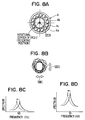
- FIG. 8A A state of superposition of the phenomenon shown in Fig. 4 on that shown in Fig. 5 is shown in Fig. 8.
- Fig. 8B A state of superposition of the phenomenon shown in Fig. 4 on that shown in Fig. 5 is shown in Fig. 8.
- the position of the rotational center of the axle 2 shown in Fig. 8A changes in accordance with loci each resembling a spiral as shown in Fig. 8B which is an enlarged diagram depicting the axle 2. Movements of the position of the rotational center of the axle 2 are measured from two angles, that is, in two directions different from each other by 90 degrees. The two directions are an up & down direction and a left-right direction shown in Figs. 8B, 8C and 8D.
- a resonance frequency of 95 Hz is obtained for the angle of the up & down direction as shown by a solid line in Fig. 8C.
- a resonance frequency of 70 Hz is obtained as shown by a solid line in Fig. 8D.
- the resonance frequency for the angle of the up & down direction decreases from 95 Hz as shown by a change from a solid line to a dashed line in Fig. 8C.
- the resonance frequency for the angle of the left-right direction decreases from 70 Hz as shown by a change from a solid line to a dashed line in Fig. 8D.
- the resonance frequency in the back & forth direction of the vehicle changes from 95 Hz to 80 Hz while the resonance frequency in the left-right direction of the vehicle changes from 70 Hz to 60 Hz.
- the amount and the period of the elastic deformation of the ball 4c or the like employed in the bearing 4 are changed by a variation in tire air pressure.
- the amount of eccentricity or the period of eccentricity of the rotational center of the bearing 4 vary in a range corresponding to a frequency range of about 60 Hz to 120 Hz.
- the rotational center of the axle 2 is also put at an eccentric position with its amount of eccentricity or its period of eccentricity varying in the same way. Due to such an effect, the gap between the sensor unit 50 and the projections 11 of the rotor 10 varies.
- the gap variations are conveyed by a signal generated by the wheel rotation sensor 100 as changes in amplitude and/or period.
- Fig. 9 is a diagram showing movements of the rotational center of the bearing 4 (or the rotational center of the rotor 10) relative to the sensor unit 50 of the wheel rotation sensor 100 with the lapse of time at a high speed of the vehicle. Much like the movements shown in Fig. 8B, the rotational centers move along loci each resembling a spiral.
- Fig. 10 is a diagram showing a signal which represents the rotational speed of a wheel and is picked up by an electromagnetic pickup when the rotational center of the rotor 10 moves.
- the waveform of the signal includes changes caused by movements of the rotational center attributed to eccentricity of the bearing 4 of the rotor 10.
- Fig. 11 is a diagram showing results of a frequency analysis such as the FFT (Fast Fourier Transform) processing carried out on the signal representing the rotational speed of a wheel like one shown in Fig. 10.
- a solid-line curve shown in Fig. 11 represents a resonance waveform for a normal air pressure. When the air pressure decreases, however, the resonance frequencies become lower as indicated by a dashed-line curve.
- the air pressure of a tire can be detected or estimated indirectly at a high speed of the vehicle by using a phenomenon of a varying period of eccentricity of the rotor 10, that is, a varying period of eccentricity of the axle 2.
- the period of eccentricity of the rotor 10 changes at a high speed of the vehicle due to the eccentricity of the bearing 4.
- indirect estimation of the air pressure of a tire can be implemented by using resonance frequencies not only at low and medium speeds of the vehicle, but also in a high-speed range. It should be noted that the detection and/or the estimation of the air pressure of a tire can be implemented by carrying out an analysis based on software without providing a new actuator for estimating the air pressure of a tire.
- this technique can be applied to a vehicle employing an anti-skid control device by monitoring a signal generated by the wheel rotation sensor 100 installed on each wheel in almost all vehicles over the entire speed range, from a practical lower limit of about 10 Km/h to an upper limit permitted by a law.
- a signal generated by a wheel rotation sensor having an electromagnetic-pickup type to represent the rotational speed of a wheel is subjected to a frequency analysis.
- eccentricity of the rotor 10 or the axle 2 can also be detected at a high speed of the vehicle by measuring the eccentricity of the rotor 10 and the axle 2 from a signal generated by a general-purpose displacement sensor 101 of typically a laser type or an eddy-current type shown in Figs. 12 and 13 and analyzing results of the measurement.
- a sensor 102 such as a piezoelectric device or a distortion gage generates a signal which is subjected to a frequency analysis to estimate an air pressure of a tire in the same way as the embodiment described so far.
- the sensor 102 varies its output in accordance with a displacement resulting from an applied force.
- the piezoelectric device 102 can also be used to detect an axial force applied to the axle 2 presumably serving as a base of eccentricity of the rotor 10, or a force ⁇ applied by the axle 2 to the axle housing 3 in the radial direction as shown in Fig. 15 in order to provide the same effects.
- an acceleration sensor 103 for detecting a vibration of the axle housing 3 can also be provided as shown in Figs. 16 and 17 in order to provide the same effects. It should be noted that, in this case, the acceleration sensor 103 can be provided on the cover 5 as shown in Fig. 16 or attached directly to the axle housing 3.
- the eccentricity of the axle 2 can be detected as variations in distance L3 in order to provide the same effects.
- steps 115 and 116 can be inserted into the flowchart shown in Fig. 3 at a location before the step 120 of at which frequencies of resonance attributed to a spring constant are found as described earlier.
- the speed of the vehicle is detected.
- the detected speed of the vehicle is examined to determine whether the speed is included in a predetermined high-speed range. If the detected speed of the vehicle is determined to be not included in the predetermined high-speed range, a resonance frequency close to the normal resonance frequency of 40 Hz is found at the step 120 to be compared with a resonance-frequency criterion value of typically 40 Hz.
- a resonance frequency close to the normal resonance frequency of 70 Hz or 95 Hz that is, a frequency of resonance attributed to eccentricity of the rotational center of the axle 2 or the rotor 10.
- the resonance frequency used in the estimation of the air pressure of a tire or the estimation of variations in tire air pressure based on the eccentricity of the rotational center of the axle 2 in a high-speed range is a frequency close to 70 Hz or 95 Hz. Note, however, that it is quite within the bounds of possibility that the frequency of resonance caused by the eccentricity of the rotational center of the axle 2 changes in accordance with factors like the type of the tire such as a temper tire and a bias tire, the diameter of the tire or the rigidity of a member supporting the bearing 4.
- the frequency of resonance caused by the eccentricity of the rotational center of the axle 2 is identified in accordance with the factors such as the type of the tire to be used in the estimation of the air pressure of a tire or the estimation of variations in tire air pressure.
- Fig. 21 is a block diagram showing the configuration of a monitor device for monitoring the air pressure of a tire.
- rotors 10a to 10d are provided on wheels 6a to 6d of the vehicle respectively. Rotated along with the wheels 6a to 6d, the rotors 10a to 10d each have slits or projections on the outer circumferential surface thereof. Wheel rotation sensors 50a to 50d of the electromagnetic-pickup type are provided to face the outer circumferential surfaces of the rotors 10a to 10d respectively.
- a coil senses a change in magnetic flux passing through a core not shown in the figure and converts the change into an electrical signal supplied to an ECU (Electronic Control Unit) 7.
- the ECU 7 carries out signal processing such as FFT processing on the electrical signal received from wheel rotation sensor 50j to find the resonance frequency of the tire of the wheel 6j.
- the ECU 7 determines whether a drop in tire air pressure exists from a change in resonance frequency.
- a result of the determination indicating a drop in tire air pressure is reported to a passenger through an alarm unit 8.
- An independent alarm indicating a drop in tire air pressure can be reported to a passenger through the alarm unit 8 individually for each of tires 6a to 6d or can be reported only when at least one of the tires 6a to 6d is in a state of a decreased air pressure of a tire 6j.
- a rotor 10 is a representative of the rotors 10a to 10d.
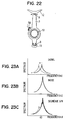
- the wheel rotation sensor 50 is provided on an axle housing 3 which is supported by an upper arm 12 at a support point A on the upper side through a ball joint and supported similarly by an lower arm 13 at a support point B on the lower side also through a ball joint.
- the rotor 10 is provided on an axle or a member which rotates along with the axle. It should be noted that that the axle and the member themselves are not shown in the figure.
- the axle housing 3 itself, on which the wheel rotation sensor 50 is provided, vibrates in the back & forth direction of the vehicle indicated by arrows in the figure at mutually opposite phases at the support points A and B.
- This a vibration is inherent a vibration of an unsprung caused by, among other things, a suspension vibration as described earlier.
- the vibration of the axle housing 3 causes a rotational vibration in the wheel rotation sensor 50 in directions indicated by arrows in the figure.
- the rotational vibration of the wheel rotation sensor 50 in turn brings about a displacement of the wheel rotation sensor 50 relative to the rotor 10.
- the displacement is included in an output signal as frequency-component noise shown in Fig. 23B.
- Fig. 23A is a diagram showing a shift of the waveform of a spectrum peaked at a resonance frequency with no noise included in a signal generated by the wheel rotation sensor 50.
- the shift is caused by a decrease in tire air pressure.
- a solid line represents a waveform before the air pressure of the tire decreases and a dashed line represents a waveform after the air pressure of the tire decreases.
- Fig. 23A shows a case of a high S/N ratio
- the resonance frequency is much shifted by a decrease in tire air pressure.
- Fig. 23B is a diagram showing the waveform of a spectrum obtained as a result of addition of noise to the spectrum shown in Fig. 23A. In this case, a change from a solid line to a dashed line is blocked by the noise component as shown in Fig. 23C and the S/N ratio decreases considerably.
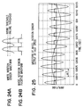
- the sinusoidal waveform of the signal generated by the wheel rotation sensor 50 as shown in Fig. 24A can be reshaped into a pulsative waveform representing the speed of the vehicle as shown in Fig. 24B by using a rising-edge threshold and a falling-edge threshold shown in Fig. 24A.
- Fig. 25 is a diagram showing a typical waveform of a signal generated by the wheel rotation sensor 50 at a high speed of the vehicle. It should be noted that the figure shows a compound waveform of a signal representing the rotational speed of the wheel with a frequency of 800 Hz and a signal representing consecutive eccentricity periods of the wheel rotation sensor 50 occurring at a frequency of 80 Hz. The eccentricity periods occur as relative eccentricity caused by typically an installation error of the wheel rotation sensor 50 relative to the rotor 10. It should be noted that the pulsative waveform shown in Fig. 24B is based on the variation period of a unit time ⁇ T of a compound waveform shown in Fig. 27A.
- the period between the rising edge of a pulse and the falling edge of the pulse varies due to the period of eccentricity so that the apparent waveform can be lengthened and shortened.
- the period ⁇ T between the rising edge of a pulse and the rising edge of the next pulse can also be changed.
- the waveform of the signal is an ideal sinusoidal waveform.
- the aforementioned rotational vibration accompanying a suspension vibration or the like happens to be the same as the eccentricity periods occurring at a frequency of 80 Hz as shown in Fig. 25.
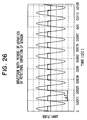
- the variations of ⁇ T itself shown in Fig. 26 approximately match those shown in Fig. 25. That is, the pulsative waveform of the output signal shown in Fig. 25 becomes a waveform shown in Fig. 27A.
- FIG. 27A and the period ⁇ T of a pulsative signal including noise caused by the a rotational vibration of the wheel rotation sensor 50 shown in Fig. 26 represent an equivalent period of variation like one shown in Fig. 27C.
- the rotational vibration of the wheel rotation sensor 50 is caused by a vibration of the axle housing 3 which is attributed to a vibration of an unsprung.
- the output signal of the case shown in Fig. 25 can not be distinguished from the output signal including noise caused by a rotational vibration of the wheel rotation sensor 50 for the case shown in Fig. 26.
- a ratio of ⁇ TL/ ⁇ TH is considered where the symbol ⁇ TH denotes a period of time between a raising edge of a pulse and a falling edge of the same pulse while the symbol ⁇ TH denotes a period of time between a falling edge of a pulse and a raising edge of the next pulse as shown in Figs. 28A to 28D.
- ⁇ TH denotes a period of time between a raising edge of a pulse and a falling edge of the same pulse
- ⁇ TH denotes a period of time between a falling edge of a pulse and a raising edge of the next pulse as shown in Figs. 28A to 28D.
- the ratio of ⁇ TL/ ⁇ TH has a fixed value as shown in Fig. 28D.
- a first modified version of the second embodiment is explained by referring to Fig. 29.
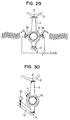
- two wheel rotation sensors 55 and 56 are provided on a rotor 10 with the wheel rotation sensors 55 and 56 facing each other.
- a difference between signals output by the wheel rotation sensors 55 and 56 are used for computing the rotational speed of the wheel. Since noise included in the signal generated by the wheel rotation sensor 55 has the same phase as noise included in the signal generated by the wheel rotation sensor 56, the noise components output by the wheel rotation sensors 55 and 56 cancel each other.
- a component representing eccentricity periods as shown in Fig.
- a second modified version of the second embodiment is explained by referring to Fig. 30.
- noise is eliminated by software in accordance with a flowchart shown in Fig. 31 or 32.
- a height sensor 60 is provided on a low arm 13. It should be noted that, since a vehicle has 4 low arms 13, 4 height sensors 60 are required for the vehicle with each of the height sensors 60 provided for one of the low arms 13.
- the height sensor 60 monitors a stroke which varies due to a back & forth vibration of the low arm 13 in order to detect generation of noise caused by a rotational vibration occurring in a wheel rotation sensor 50.
- Fig. 32 shows a flowchart representing processing to make a correction in a time domain. As shown in the figure, the flowchart begins with a step 10 at an ignition-on time to start the engine. At this step, the rotational speed of each wheel is found from a signal generated by the wheel rotation sensor 50 for the wheel.
- the rotational speed of the wheel is corrected. Details of the correction are represented by steps 21 to 24 of a sub-flowchart shown in the same figure.
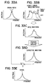
- the waveform of a signal representing variations in height is input from the height sensor 60.
- the waveform is represented by a solid line in Fig. 33B.
- BPF Band-Pass Filter
- frequencies at which noise is generated can be measured and predicted in advance.
- the spectrum of the noise is represented by a dashed line in Fig. 33B.
- With the noise frequencies known, required frequency components can be extracted from a signal generated by the height sensor 60 as if the signal were passed through a band-pass filter.
- a waveform shown in Fig. 33C is obtained.
- the extracted signal is subjected to FFT processing.
- a correction waveform for the signal representing the rotational speed of the wheel is produced based on a transfer function measured in advance for predicting and computing a vibration (a rotational vibration) at the position of the wheel rotation sensor 50 based on a vibration (a rotational vibration) at the position of the height sensor 60.
- the waveform produced at the step 24 is shown in Fig. 33D. This waveform can be regarded as result of wave reshaping of noise included in a signal generated by the height sensor 60.
- a step 30 FFT processing for detecting variations in resonance frequency caused by changes in tire spring constant is carried out for extracting components effective for estimation of the air pressure of a tire based on the corrected signal representing the rotational speed of the wheel.
- the processing carried out at the step 30 results in a waveform shown in Fig. 33E.
- the correction waveform produced at the step 24 is subtracted from a waveform which was obtained from the FFT processing and includes noise caused by the rotational vibration of the wheel rotation sensor 50.
- a step 40 a variation in resonance frequency occurring in a time unit is found.
- the processing goes on to a step 50 to determine whether the air pressure of the tire has decreased from the variation found at the step 40. If the air pressure of the tire has decreased, a warning message is displayed at a step 60.
- the flowchart shown in Fig. 32 represents processing to correct elimination of noise in a frequency domain.
- the flowchart begins with a step 150 at which the rotational speed of each wheel is found in the same way as the step 10. Then, at a step 160, FFT processing for detecting variations in resonance frequency caused by changes in tire spring constant is carried out based on a signal representing the rotational speed of the wheel. At the next step 170, a result of the FFT processing obtained at the step 160 is corrected.
- the basis of the correction is represented by steps 21 to 24 of a sub-flowchart of the same figure which are the same as the steps 21 to 24 respectively of the flowchart shown in Fig. 31.
- a noise component is eliminated from the result of the FFT processing obtained at the step 160 by a vibration of the wheel rotation sensor 50 itself based on a result of the FFT processing carried out on a signal output by the height sensor 60 at the step 23 and a correction waveform produced at the step 24.
- a resonance frequency is found based on the result of the FFT processing corrected at the step 170.
- the processing then goes on to steps 50 and 60 which are the same as the steps 50 and 60 of the flowchart shown in Fig. 31.
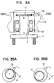
- the axle 2 is magnetized to improve the S/N ratio.
- the axle 2 is magnetized so that one end of the axle 2, that is, a member of the axle 2 attached to the rotor 10, becomes a single pole of magnetism.
- the rotor 10 moves from a position closest to the wheel rotation sensor 50 as shown in Fig. 35A to a position farthest from the wheel rotation sensor 50 as shown in Fig. 35B.
- the change of a flux passing through a coil of the wheel rotation sensor 50 caused by an eccentric rotational movement of the axle 2 or the rotor 10 increases, allowing sensitivity to be improved.
- the strength of the signal can be increased relatively to noise caused by a rotational movement of the wheel rotation sensor 50 itself, allowing the S/N ratio to be increased.
- a wheel rotation sensor 50 is attached to an axle housing 3 connecting an upper arm 12 and a lower arm 13 as described earlier.
- a rotor 10 rotates along with an axle which is not shown in the figure.
- the wheel rotation sensor 50 is installed to face the rotor 10.
- the rotor 10 and the axle have components that vibrate in a direction indicated by an arrow X and a direction indicated by an arrow Y.
- the arrows X and Y indicate the back & forth and the up & down directions respectively of the vehicle.
- the vibrations in the X and Y directions are caused by a vibration of an unsprung such as a suspension vibration and a vibration introduced to the tire from the surface of the road while the vehicle is running.
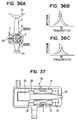
- the frequency of tire resonance caused by a spring constant of the tire can be extracted as vibration components in the X and Y directions of the rotor 10. That is, the frequency of the tire resonance caused by the vibration component in the Y direction is extracted at about 70 Hz for the normal air pressure of the tire as indicated by a solid line in Fig. 36B. On the other hand, the frequency of the tire resonance caused by the vibration component in the X direction is extracted at about 80 Hz for the normal air pressure of the tire as indicated by a solid line in Fig. 36C. It should be noted that, when the air pressure of the tire decreases, the resonance frequencies also decrease as indicated by shifts from the solid lines to dashed lines shown in Figs. 36B and 36C.
- the vibration generated in the wheel rotation sensor 50 itself by the suspension vibration occurs in the rotational direction of the rotor 10 indicated by an arrow Z in the figure. Since the vibration in the rotational direction occurs in the rotational direction of the rotor 10, this vibration becomes noise which lowers the level of a signal representing the rotational speed of the wheel.
- the vibrations in the X and Y directions that is, the vibration in the radial direction of the rotor 10 increase, raising the level of the signal generated by the wheel rotation sensor 50 in comparison with the noise to provide an improved S/N ratio.
- a member affecting the signal generated by the wheel rotation sensor 50 is vibrated in the radial direction of the rotor 10 so that the vibration passing through the wheel rotation sensor 50 in the radial direction of the rotor 10, that is, in the X or Y direction required in the estimation of the tire air pressure, is strengthened to improve the S/N ratio.
- a coil 21 experiencing variations in magnetic flux passing through a yoke core 20 in the wheel rotation sensor 50 is vibrated. A concrete structure of the wheel rotation sensor 50 is explained by referring to Fig. 37.
- the structure comprises the yoke core 20 and the coil 21.
- the yoke core 20 has a member facing the rotor 10.
- the coil 21 generates an electromotive force in accordance with a variation in magnetic flux passing through the yoke core 20 and outputs the electromotive force as a signal generated by the wheel rotation sensor 50 to an ECU.
- the yoke core 20 is magnetized by a permanent magnet 23.
- the yoke core 20, the coil 21 and the permanent magnet 23 are molded and a resin housing 24 is created.
- the coil 21 is installed in such a way that the coil 21 can be moved in the axial direction of the yoke core 20.
- the coil 21 can be slightly vibrated by a spring 22 in the axial direction of the core 20, that is, in the radial direction of the rotor 10 shown in Fig. 36 or the direction indicated by the arrow X in Fig. 37.
- the coil 21 of the wheel rotation sensor 50 is capable of increasing the vibration in the radial direction of the rotor 10 which is dependent on the air pressure of the tire and thus required in the estimation of the air pressure. That is, the vibration of the coil 21 in the radial direction of the rotor 10 results in variations in magnetic flux. Thus, the output is increased in addition to the variations in magnetic flux caused by the vibration of the coil 21 in the radial direction of the rotor 10. It should be noted that the vibration in the rotational direction of the rotor 10 which becomes noise occurs in a direction perpendicular to the movement direction of the coil 21. An effect of preventing the vibration in the rotational direction of the rotor 10 caused by the movement of the coil 21 is very small.
- the S/N ratio of a signal component in the radial direction of the rotor 10 which is included in a signal generated by the wheel rotation sensor 50 and dependent on the air pressure of the tire increases, allowing the sensitivity and the precision of the processing to estimate the air pressure of the tire to be improved.
- the permanent magnet 23 is slightly vibrated in the axial direction of the yoke core 20, that is, the radial direction of the rotor 10, instead of vibrating the coil 21 as implemented in the third embodiment. That is, the permanent magnet 23 supported by a spring 31 can be moved in the housing 24 in the axial direction of the yoke core 20.
- a stopper 30 is provided as a support plane of the spring 31.
- the yoke core 20 penetrates the stopper 30.
- a second modified version of the third embodiment is explained by referring to Fig. 39.
- the coil 21 or the permanent magnet 23 is vibrated in the wheel rotation sensor 50 in the radial direction of the rotor 10 so as to bring about variations in magnetic flux inside the wheel rotation sensor 50 itself.
- a magnetic vibration system 100 is provided at a position in close proximity to the wheel rotation sensor 50 which is a conventional wheel rotation sensor. The magnetic vibration system 100 brings about external variations in magnetic flux in the radial direction of the rotor 10 for the wheel rotation sensor 50.
- a permanent magnet 101 is supported by a spring 103 and vibrated in a housing 104 in the radial direction of the rotor 10, that is, the axial direction of a core 102.
- the vibration of the permanent magnet 101 results in variations in magnetic flux which pass through the coil 21, having an effect on the wheel rotation sensor 50.
- variations in magnetic flux related to the vibration in the radial direction of the rotor 10 in the signal generated by the wheel rotation sensor 50 are magnified by the magnetic vibration system 100.
- the S/N ratio of the signal generated by the wheel rotation sensor 50 is improved.
- Fig. 40 is a diagram showing a wheel periphery surrounding a wheel employed by a vehicle having an ABS system.
- a wheel rotation sensor 50 is attached to an axle housing 3 connecting an upper arm 12 to a lower arm 13.
- a rotor 10 is provided to face the wheel rotation sensor 50. Slits or projections are created over the entire circumference of the rotor 10.
- a magnetic flux of a magnetic circuit formed between the wheel rotation sensor 50 and the rotor 10 changes. The changes in magnetic field are picked up by a coil in the wheel rotation sensor 50. It should be noted that the rotor 10 rotates along with an axle which is not shown in the figure.
- the wheel rotation sensor 50 (representing the wheel rotation sensors 50a to 50d) and the rotor 10 (representing the rotors 10a to 10d) are provided on the wheel 6 (representing the wheels 6a to 6d). Signals picked up at the wheel rotation sensors 50a to 50d are supplied to an ECU (Electronic Control Unit) 7. Through a warning device 8, a passenger is informed of a decrease in tire air pressure detected in the processing carried out at the steps 100 to 140 of flowchart shown in Fig. 3.
- ECU Electronic Control Unit
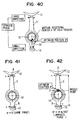
- Fig. 40 is a diagram showing the configuration of a fourth embodiment using a representative front axle housing with two support points.
- the wheel rotation sensor 50 is placed at a position ⁇ closest to an estimated virtual rotational center ⁇ of the axle housing 3.
- a member of the axle housing 3 has a minimum vibration amplitude.
- the vibration of the wheel rotation sensor 50 is also reduced.
- the amount of noise caused by the vibration of the wheel rotation sensor 50 and included in a signal generated by the wheel rotation sensor 50 can be reduced considerably.
- the virtual rotational center ⁇ is found as follows. First of all, a G sensor or a distortion gauge is used for measuring vibration behaviors at a support point A at a junction between the axle housing 3 and an upper arm 12 and at a support point B at a junction between the axle housing 3 and a lower arm 13. To be more specific, the amplitudes and the phases at the support points A and B are each expressed accurately as a vector. In this case, measurements along two axes, namely, an up & down axis and a left-right axis in the figure, are desirable. If the behavior of the vibration such as the amplitude of the vibration becomes obvious from a measurement in only one direction, however, a single-axial measurement is sufficient.
- Vibrations at the support points A and B are sensed in this way and subjected to a frequency analysis. Then, an amplitude (that is, a vibration vector) and a phase difference at a frequency of noise included in a signal generated by the wheel rotation sensor 50 are computed.
- the virtual rotational center ⁇ of the axle housing 3 exists in directions perpendicular to the vibration vectors at the support points A and B. In dependence on the phase difference, the virtual rotational center ⁇ of the axle housing 3 can or can not be determined at 1 point.
- a case in which the virtual rotational center ⁇ of the axle housing 3 can be determined at 1 point is taken into consideration.
- the optimum position ⁇ of the wheel rotation sensor 50 is determined for such a case in accordance with the following order.
- an optimum position ⁇ closest to the virtual rotational center ⁇ of the axle housing 3 is selected by taking, among other things, the shape of the wheel rotation sensor 50 into consideration. Then, if there are a plurality of optimum positions ⁇ closest to the virtual rotational center ⁇ of the axle housing 3, an optimum position close to a support point with a smaller amplitude of the vibration vector is selected.
- the amplitude and the phase at the support point A are the same as those at the support point B as shown in Fig. 41, one may assume that neither vibration on the axle housing 3 nor vibration of the wheel rotation sensor 50 caused by the vibration of the axle housing 3 exists and no noise is included in a signal generated by the wheel rotation sensor 50.
- the sensor wheel 50 can be placed at any position.
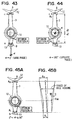
- the virtual rotational center ⁇ moves. From the dynamics-symmetry point of view, however, a middle point between the support points A and B can be regarded as the virtual rotational center ⁇ .
- the virtual rotational center ⁇ slips to a position on an outer side of the support point A or B on an extension of a line connecting the support point A to the support point B. If the virtual rotational center ⁇ slips to a position on the outer side of the support point B on the extension of the line connecting the support point A to the support point B as shown in Fig. 43, for example, an optimum position ⁇ for installing the wheel rotation sensor 50 is located at a position on the outer side of the support point B on the extension of the line connecting the support point A to the support point B.
- the virtual rotational center ⁇ is located at a middle point on the line connecting the support point A to the support point B with a ratio of the distance between the middle point and the support point A to the distance between the middle point and the support point B equal to Au/Al where the symbol Au denotes the amplitude at the support point A and the symbol Al denotes the amplitude at the support point B.
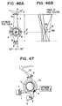
- Figs. 45A, 45B, 46A and 46B are diagrams each showing a case in which the phases at the support points A and B are neither 0 nor 180 degrees and the amplitude at the support point A is different from that at the support point B.
- Figs. 45A and 45B are diagrams each showing a case of (0 degrees ⁇ ⁇ ⁇ 90 degrees) where the symbol ⁇ denotes the phase. In this case, any point between a member X90 and the support point B or between the center of the rotor 10 shown in Fig.
- Figs. 46A and 46B are diagrams each showing a case of (90 degrees ⁇ ⁇ ⁇ 180 degrees) where the symbol ⁇ denotes the phase. In this case, the loci converge from the position X90 to a point X.
- the position X is determined by a ratio of Au to Al where the symbols Au and Al denote the amplitudes at the support points A and B respectively.
- the optimum position ⁇ is determined at locations in close proximity to two points on the axle housing 3.
- the optimum position ⁇ can be determined by using the technique described above for a plurality of support points as is the case with a rear axle housing 3a having support points A, B and C as shown in Fig. 47.
- rotors 10a to 10d are provided on wheels 6a to 6d of a vehicle respectively. Rotated along with the wheels 6a to 6d, the rotors 10a to 10d each have slits or projections on the outer circumferential surface thereof. Wheel rotation sensors 50a to 50d of the electromagnetic-pickup type are provided to face the outer circumferential surfaces of the rotors 10a to 10d respectively.
- a coil in the sensor 50j senses a change in magnetic flux passing through a core not shown in the figure and converts the change into an electrical signal supplied to an ECU (Electronic Control Unit) 7.
- the ECU 7 carries out signal processing such as FFT processing on the electrical signal received from wheel rotation sensor 50j to find the resonance frequency of the tire of the wheel 6j.
- the ECU 7 determines whether a drop in tire air pressure exists from a change in resonance frequency.
- the ECU 7 carries out BPF (Band-Pass Filter) processing on the signal received from the wheel rotation sensor 50j to extract a required frequency region and performs a process to generate a correction waveform based on a transfer function.
- the correction waveform is used for elimination of noise from the signal received from the wheel rotation sensor 50j or a result of the FFT processing based on this signal.
- an acceleration sensor 99 is provided at a location in close proximity to a propeller shaft, a drive shaft (or an axle housing) or a differential of the vehicle. The acceleration sensor 99 detects the vibration state of a vibration system at the propeller shaft, the drive shaft or the differential.
- the ECU 7 determines the existence of a drop in tire air pressure from a change in resonance frequency, the result of the determination indicating a drop in tire air pressure is reported to a passenger through an alarm unit 8.
- An independent alarm indicating a drop in tire air pressure can be reported to a passenger through the alarm unit 8 individually for each of tires 6a to 6d or can be reported only when at least one of the tires 6a to 6d is in a state of a decreased air pressure of the tire 6j.
- Fig. 49A is a diagram showing curves representing a change in resonance frequency waveform caused by a drop in tire air pressure for a case in which a signal output by the wheel rotation sensor 50j includes noise.
- a spectrum peaked at a resonance frequency is represented by a solid-line waveform.
- the spectrum is represented by a dashed-line waveform.
- Fig. 49A shows a case of a high S/N ratio, the resonance frequency is much shifted by a decrease in tire air pressure.
- Fig. 49B is a diagram showing the waveform of a spectrum obtained as a result of addition of noise to the spectrum shown in Fig. 49A. In this case, a change from a solid line to a dashed line is blocked by the noise component as shown in Fig.49C and the S/N ratio decreases considerably.
- the noise signal component shown in Fig. 49B includes noise generated by a vibration model shown in Fig. 50A.
- a vibration model shown in Fig. 50A As shown in Fig. 50A, an engine 210, a gear unit 211 receiving a driving force from the engine 210, a propeller shaft 212, a differential 213 and a drive shaft 214 constitute a bending and torsional vibration model.
- a vibration model in the first place, there is a vibration of the propeller shaft 212 in the up & down direction of the car body or a direction indicated by an arrow ⁇ , that is a windup vibration caused by an up & down movement of the suspension as shown in Fig. 50B.
- This vibration is a vibration with a frequency of about 35 Hz.
- a bending vibration of the drive shaft 214 in the up & down direction of the car body or a direction indicated by an arrow ⁇ as shown in Fig. 50C.
- the bending vibration of the drive shaft 214 is a primary bending vibration with respect to an axle housing to which the wheel rotation sensor 50j is attached. This vibration is a vibration with a frequency of about 70 Hz.
- vibration components included in a signal generated by the wheel rotation sensor 50j and required in estimation of the air pressure of the tire When the vehicle is running, resonance occurs at frequencies of about 40 Hz and 70 Hz due to a vibration caused by the surface of the road and experienced by the tire and a vibration inherent in the spring unit of the tire of the carcass unit. That is, vibration components including a component having a frequency of resonance caused by a spring constant of the tire are included in a signal generated by the wheel rotation sensor 50j. By extracting the vibration components, the air pressure of the tire can be estimated. It should be noted that resonance frequencies of about 40 Hz and 70 Hz indicate a normal air pressure of the tire.
- the frequencies of resonance drop from 40 Hz to typically 35 Hz and from 70 Hz to 65 Hz for example. It should be noted that the resonance frequency of about 70 Hz can be considered to be the frequency of a secondary vibration of the tire. It is also worth noting that, at low and medium speeds of the vehicle, the magnitude of the spectrum at the resonance frequency close to a primary-resonance frequency of 40 Hz of the vehicle is large. In the high-speed region, on the other hand, the magnitude of the spectrum at the resonance frequency of about 70 Hz of the vehicle is large.
- an acceleration sensor 99 shown in Fig. 48 is used for detecting the vibration of the driving system.
- a signal generated by the acceleration sensor 99 is detected as a vibration with the vibrations of Figs. 50B to 50D superposed thereon. These vibrations are a noise vibration component.
- a noise component shown in Fig. 49B can be extracted.
- an acceleration sensor provided on an anti-skid control device for a 4-wheel driven vehicle or an acceleration sensor provided on a car-behavior control device for improving a turning trace characteristic of the vehicle can be used as the acceleration sensor 99. In this case, it is not necessary to separately provide a new acceleration sensor dedicated to the device for estimating the air pressure of a tire.
- Figs. 51 and 52 are the same as the flowcharts shown in Figs. 31 and 32 respectively except that a step 21a of the former replaces the step 21 of the latter and the acceleration sensor 99 of the former replaces the height sensor 60 of the latter.
- the waveform of a signal representing variations in vehicle height is input from the height sensor 60.
- the waveform of a detection signal is input from the acceleration sensor 99.
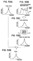
- Figs. 53A to 53E correspond to Figs. 33A to 33E respectively except that Fig. 53B shows the waveform of the detection signal generated by the acceleration sensor 99 instead of the waveform represented by the solid line in Fig. 33B for the height sensor 60.
Landscapes
- Engineering & Computer Science (AREA)
- Mechanical Engineering (AREA)
- Physics & Mathematics (AREA)
- Mathematical Physics (AREA)
- Measuring Fluid Pressure (AREA)
Abstract
A tire air pressure is accurately estimated by processing vibrations including vibration components representing a rotational eccentricity of an axle (2) of a vehicle wheel even at a high vehicle running speed. <IMAGE>
Description
The present invention relates to a tire air pressure
estimating device for indirectly estimating the air pressure
of a tire by carrying out a frequency analysis on a signal
generated by typically a wheel speed sensor. More
particularly, the present invention relates to improvement
of an S/N ratio of the signal generated by the wheel speed
sensor by substantially eliminating noise included in the
signal in indirect estimation of the air pressure of the tire.
There is known a tire air pressure estimating device
whereby variations in rotational speed dependent on the air
pressure of a wheel tire are detected by carrying out a
frequency analysis on a signal generated by typically a wheel
speed sensor as is disclosed for example in JP-A-No. H5-133831.
In such a tire air pressure estimating device, a signal
generated by a wheel speed sensor for an antilock brake system
(ABS) is supplied to an electronic control unit (ECU) as pulses
through an ordinary wave shaping circuit to be recognized
by the ECU. The pulses are used as a base for reproducing
the original analog waveform from which the rotational speed
of the wheel is found. A resonance frequency dependent on
a spring constant of the tire is directly found by applying
an FFT (Fast Fourier Transform) technique or a linear
estimation technique to the rotational speed of the wheel
reproduced by approximation.
As an alternative, variations in resonance
frequency are indirectly found. Such variations are
dependent on a spring constant of the tire which is found
as an estimated value by applying a disturbance observer
technique or the like. As described above, the resonance
frequency dependent on the air pressure of the tire or an
equivalent quantity of the resonance frequency is computed
to find the current air pressure of the tire which is then
compared with the normal air pressure of the tire obtained
at an initial time. If the result of the comparison indicates
a decrease in tire air pressure, a warning is given to the
driver.
In a device for estimating the air pressure of a
tire by carrying out such a frequency analysis, a decrease
in tire air pressure is detected as a change in a resonance
frequency of a tire spring unit from about 40 Hz as indicated
by a shift from a solid line to a dashed line shown in Fig.
20A and 20B. Such a decrease can then be used to estimate
the air pressure of the tire itself.
At a vehicle speed not exceeding about 60 Km/h,
the gain of the frequency spectrum of an observed signal is
large as shown in Fig. 20A. In this case, a change in air
pressure of the tire can be estimated satisfactorily from
a variation in resonance frequency. At a vehicle speed
exceeding about 60 Km/h, on the other hand, the gain of the
frequency spectrum of the observed signal is small as shown
in Fig. 20B. In this case, it is quite within the bounds
of possibility that the air pressure of the tire is difficult
to estimate particularly at a high vehicle speed.
In addition, the wheel speed sensor used in such
a tire air pressure estimating device is provided on an axle
housing of the vehicle. Attached to lower and upper arms,
the axle housing experiences propagation of a vibration of
a propeller shaft, a drive shaft and a differential. In
addition, the wheel speed sensor is installed to face a rotor
which exhibits projections or has slits on the circumferential
surface thereof. The rotor is attached to an axle or a member
which rotates along with the axle. The axle housing thus
vibrates in accordance with a vibration of an unsprung which
is inherent in the vehicle and accompanies a suspension
vibration and the like. Accordingly, the wheel speed sensor
itself also vibrates inevitably in accordance with the
vibration of the unsprung. The vibration of the wheel speed
sensor itself appears as noise in a signal generated by the
sensor, raising a problem of a decreased S/N ratio of the
signal.
It is thus an object of the present invention to
provide a tire air pressure estimating device capable of
estimating the air pressure of a tire with a high degree of
accuracy even at a high vehicle speed.
As a first means for solving the problems described
above, the present invention provides a tire air pressure
estimating device for estimating the air pressure of a tire
or detecting a change in air pressure of the tire by utilizing
eccentricity of the shaft center of a wheel. At a high vehicle
speed, the eccentricity of the shaft center of a wheel vibrates
at a large amplitude. The tire pressure estimating device
implements estimation of the air pressure of a tire or
detection of a change in air pressure of the tire based on
a relation between a vibration component caused by
eccentricity and the air pressure of the tire.
It should be noted that the vibration component
caused by the eccentricity of an axle can be extracted by
carrying out a frequency analysis on a signal generated by
a wheel speed sensor, or by observing a force applied to an
axle, a displacement or an acceleration of the axle or a
phenomenon which represents the force, the displacement or
the acceleration and occurs in the structure of the axle itself
or a structure surrounding the axle.
It is another object of the present invention to
effectively prevent the S/N ratio of a signal generated by
a vibration of the wheel speed sensor itself from
deteriorating.
As a second means for solving the problems described
above, the present invention provides: a waviness-component
extraction means for extracting a waviness component of a
vibration of a signal generated by the wheel speed sensor;
and a component separation means for separating noise included
in a signal output due to a rotational vibration of the wheel
speed sensor itself from the signal.
It is thus possible to separate an inherent noise
component caused by an error of installation of the wheel
speed sensor and a noise component included in a signal
generated by the wheel speed sensor due to the rotational
vibration of the wheel speed sensor itself attributed to an
accidental suspension vibration or the like.
As an alternative, two wheel speed sensors facing
each other are provided on an axle housing serving as a place
for installing wheel speed sensors. The air pressure of the
tire is then found from a value of synthesis of signals output
by the two wheel rotation sensors. In this scheme, a
rotational vibration noise component included in a signal
generated by one of the two wheel rotation sensors cancels
a rotational vibration noise component included in a signal
generated by the other wheel rotation sensor because of the
same phase. In addition, an eccentricity component output
as a signal by one of the two wheel rotation sensors enforces
an eccentricity component output as a signal by the other
wheel rotation sensor due to their more or less mutually
opposite phases. As a result, the magnitude of the output
eccentricity component is doubled to give an improved S/N
ratio.
As another alternative, it is also possible to
provide: a vibration detection sensor for detecting a
vibration of an unsprung of the vehicle; a noise-component
estimating means for estimating a noise component caused by
a vibration of a wheel rotation sensor itself at the position
of the wheel rotation sensor from a signal generated by the
vibration detection sensor; and a noise correction means for
adding the noised component estimated by the noise-component
estimating means to a signal generated by the wheel rotation.
sensor.
In this scheme, a noise a vibration component at
the position of the wheel rotation sensor is estimated from
a noise component at the position of the wheel rotation sensor,
and a noise component included in a signal generated by the
wheel rotation sensor and caused by a rotational vibration
of the wheel rotation sensor can be eliminated in a time or
frequency domain.
As a further alternative, an axle on which a rotor
of a wheel rotation sensor provided is magnetized so that
a variation in magnetic flux caused by eccentricity of the
rotor relative to the wheel rotation sensor is magnified by
a magnetic flux of an axle and the behavior of an output signal
is thus increased in comparison with a noise component. As
a result, the S/N ratio of a signal generated by the wheel
rotation sensor is improved.
As a third means for solving the problems described
above, a signal component in a radial component of a rotor,
which is installed to face a wheel rotation sensor and rotates
along with an axle, is increased in a signal generated by
the wheel rotation sensor in estimation of the air pressure
of a tire by detecting the signal generated by the wheel
rotation sensor. The air pressure of the tire is estimated
by extracting a vibration component attributed by a spring
constant of the tire from the signal generated by the wheel
rotation sensor and computing the resonance frequency of the
tire. The vibration component attributed by a spring
constant of the tire is a vibration component in the radial
direction of the rotor as represented by the forward/backward
directions or the upward/downward directions of the wheel.
On the other hand, a vibration component caused by a vibration
of the wheel rotation sensor itself in the rotational
direction of the rotor due to suspension a vibration or the
like becomes noise in the estimation of the air pressure of
the tire. Thus, if the vibration in the radial direction
of the rotor in the signal generated by the wheel rotation
sensor is increased, the component used in the estimation
of the air pressure of the tire is magnified rather than the
noise component of the signal generated by the wheel rotation
sensor is. As a result, the S/N ratio is raised.
In addition, by vibrating a coil in the wheel
rotation sensor in the radial direction of the rotor, the
vibration in the radial direction of the rotor, that is, a
vibration component depending on a spring constant of the
tire, can be increased with ease.
By the same token, a permanent magnet on the wheel
rotation sensor can also be vibrated.
Furthermore, instead of increasing the vibration
in the radial direction of the rotor (that is, a vibration
component depending on a spring constant of the tire) by
vibrating the internal structure of the wheel rotation sensor
itself, there is provided a magnetic vibration system having
a permanent magnet movable in the radial direction of the
rotor at a location in close proximity to the wheel rotation
sensor. With such a magnetic a vibration system, a magnetic
flux varying with a vibration of the permanent magnet in the
magnetic a vibration system has an effect on the coil of the
wheel rotation sensor. As a result, the vibration in the
radial direction of the rotor, that is, a vibration component
depending on a spring constant of the tire, can be increased.
As a fourth means for solving the problems described
above, in the air pressure of the tire estimating device
provided by the present invention, a wheel rotation sensor
is provided at a position in close proximity to a virtual
center of rotation of the axle housing by consideration of
the phases and the amplitudes of support points for an arm
on the vehicle-body side of the axle housing.
To be more specific, by considering the amplitude
at a support point supporting the axle housing with the wheel
rotation sensor provided thereon and differences in phase
among support points, a locus of a rotational vibration of
the axle housing can be predicted. If the wheel rotation
sensor is installed at a position with a minimum amplitude
of the a rotational vibration of the axle housing, that is,
if the wheel rotation sensor is installed at the rotational
center of the axle housing, the magnitude of a vibration
propagated to the wheel rotation sensor can be reduced to
a minimum and the amount of noise included in a signal output
by the wheel rotation sensor can be decreased most.
As a fifth means for solving the problems described
above, a vibration of a driving system comprising a propeller
shaft, a drive shaft, an axle housing and a differential is
detected, and a vibration component becoming noise in the
estimation of the air pressure of the tire in the vibration
is identified. Thus, the air pressure of the tire can be
estimated by taking the noise component into account. As
a result, the precision of the air pressure estimation can
be improved.
In addition, an acceleration sensor can be used
for detecting a vibration of the driving system. Furthermore,
by using an acceleration sensor employed in another device
such as an anti-skid device or a car-body behavior control
device as the acceleration sensor for detecting a vibration
of the driving system, a cost increase caused by the use of
a tire air pressure estimating device in a vehicle can be
reduced considerably. It should be noted that there are many
types of car in which the acceleration sensor used in another
device such as an anti-skid device or a car-body behavior
control device is installed on a mount portion of the
differential so that the vibration of the driving system can
be detected as a vibration at a position in close proximity
to the mount portion of the differential. Thus, the use of
the acceleration sensor employed in such another device as
the acceleration sensor for the tire air pressure estimating
device is very suitable.
It should be noted that, by detecting a vibration
of the driving system using a detection means and identifying
it using an identification means, noise in estimation of the
air pressure of a tire can be identified with a high degree
of efficiency.
Other features and advantages of the present
invention will be appreciated, as well as methods of operation
and the function of the related parts, from a study of the
following detailed description, the appended claims, and the
drawings, all of which form a part of this application. In
the drawings:
A first embodiment of the present invention is
explained by referring to diagrams as follows.
Fig. 1 is a diagram showing the periphery of the
shaft of a wheel employed in a vehicle having an ABS device.
A tire (not shown in the figure) is fixed on an axle hub 1
in such a way that the tire can be rotated by a bearing 4
having a ball 4c along with an axle 2. An axle housing 3
is provided on an outer lace 4b of the bearing 4, being fixed
on the car body by typically a steering knuckle which is not
shown in the figure either.
A rotor 10 of a wheel rotation sensor 100 is fixed
on an inner lace 4a of the bearing 4. On the edge of the
rotor 10, slits or projections 11 are created to serve as
members each used for generating changes in magnetic flux.
A sensor unit 50 of the wheel rotation sensor 100 is fixed
on the outer lace 4b. The sensor unit 50 comprises a permanent
magnet, an electromagnetic pickup, a coil and a terminal which
are not shown in the figure. The sensor unit 50 transmits
a generation current accompanying a change in magnetic flux
through the terminal to an ECU which is also not shown in
the figure. It should be noted that a cover 5 is provided
on the end of the axle 2 or on the outer side of the rotor
4. The cover 5 veils the axle 2.
A cross section II-II crossing the rotor 10 and
the sensor unit 50 as shown in Fig. 1 is shown in Fig. 2.
The distance between a protrusion 11 and the
electromagnetic pickup of the sensor unit 50 facing the
protrusion 11 changes as the rotor 10 rotates. When the
distance changes, a current generated in a coil embedded in
the sensor unit 50 also changes. The changes in such current
are output as a signal representing the rotational speed of
the wheel.
Processing to estimate a decrease in tire air
pressure by using the output of the wheel rotation sensor
100 with the configuration described above is explained by
referring to a flowchart shown in Fig. 3.
As shown in the figure, the flowchart begins with
a step 100 at which pulses to be used in calculation of the
rotational speed of the wheel are input, and processing such
as reshaping of a waveform is carried out. Then, at a next
step 110, Fast-Fourier Transform processing is carried out
on a signal representing the rotational speed of the wheel
found at the step 100. Subsequently, at the next step 120,
frequencies of resonance attributed to a spring constant of
the tire is found. For a normal air pressure of the tire
at a low or medium vehicle speed in the range 0 to 60 Km/h,
a large spectrum peaked at resonance frequencies of about
40 Hz and 80 Hz is observed. The resonance frequencies are
frequencies of resonance attributed to a spring constant of
the carcass of the tire. In particular, the output level
at the resonance frequency of 80 Hz at a low speed is very
low. It should be noted that the resonance frequencies of
about 40 Hz and about 80 Hz are frequencies of a phenomenon
of resonance between an introduced vibration caused by
roughness of the surface of a road exposed to the spring of
the tire or the carcass of the tire, and a vibration inherent
in the tire. The resonance frequency of about 40 Hz is the
frequency of a primary resonance in the rotational direction
of the tire. On the other hand, the resonance frequency of
about 80 Hz is the frequency of a secondary resonance also
in the rotational direction of the tire.
At the step 120, resonance frequencies in a
high-speed region are found. For a normal air pressure of
the tire at a high vehicle speed in the range 60 to 240 Km/h,
a spectrum peaked at resonance frequencies of about 70 Hz
and/or 95 Hz is observed. As will be described later in detail,
the resonance frequencies of about 70 Hz and 95 Hz are
frequencies of resonance a resonance vibration based on an
eccentricity phenomenon of a rotational center of the axle
2 or the rotor 10 caused by variations in tire air pressure.
It should be noted that the reason why there are two resonance
frequencies of 70 Hz and 95 Hz is that the resonance frequency
in the back & forth direction of the vehicle is different
from the resonance frequency in the up & down direction. That
is, the resonance frequency in the back and forth movements
in the radial direction of the wheel is different from the
resonance frequency in the up and down movements in the radial
direction of the wheel. Thus, in the wheel rotation sensor
of the ABS device, a compound vibration of the two vibration
elements exists. It should be noted that the up & down and
back & forth resonance frequencies are used for the sake of
convenience because, in a resonance-frequency analysis, two
axial sensors are simply installed on the car body by orienting
the X-Y axes in the up & down and back & forth directions.
Thus, the up & down and back & forth directions can be changed
in accordance with the vector direction in the
resonance-frequency analysis.
In this way, the technique of finding frequencies
of resonance dependent on the air pressure of a tire is changed.
To be more specific, for low and medium speeds, frequencies
of resonance between an introduced vibration caused by
roughness of the surface of a road and a vibration inherent
in the spring of the tire are used. In the high-speed range,
on the other hand, frequencies of resonance between an
eccentricity vibration of an axle and a vibration inherent
in the spring of the tire are used.
It should be noted that the frequencies of both
the resonance between an introduced vibration caused by
roughness of the surface of a road and a vibration inherent
in the spring of the tire and the resonance between an
eccentricity vibration of an axle and a vibration inherent
in the spring of the tire can also be found for all cases
without regard to the speed of the vehicle. Then, resonance
frequencies to be used are selected in accordance with the
speed of the vehicle. In this case, the commonly known speed
of the vehicle used in the ABS device can be utilized for
selection of resonance frequencies. In should be noted that,
instead of detecting the speed of the vehicle in this way,
comparing the detected speed of the vehicle with a criterion
value of typically 60 Km/h and determining which resonance
is to be used for selecting resonance frequencies, the
magnitudes of power spectra of resonance frequencies found
from both the two resonance phenomena are considered to
determine which resonance frequencies are more accurate, that
is, to select more accurate resonance frequencies indicated
by larger power spectra. Then, a resonance phenomenon is
determined as a base for estimation of the air pressure of
a tire.
At a step 130, a decrease in tire air pressure is
determined based on a resonance frequency found at the step
120.
Assume that the speed of the vehicle is 60 Km/h
or lower. In this case, the resonance frequencies are
frequencies of resonance between an introduced vibration
caused by roughness of the surface of a road and a vibration
inherent in the spring of the tire. Resonance-frequency
criterion values for estimating the air pressure of a tire
are 40 Hz and 80 Hz. The frequency of 40 Hz is a criterion
value for the primary resonance and the frequency of 80 Hz
is a criterion value for the secondary resonance. Assume
that resonance frequencies found at the step 120 are 35 Hz
for the primary resonance component and 75 Hz for the secondary
resonance component. In this case, the resonance frequency
of 35 Hz is compared with the criterion value of 40 Hz and
the resonance frequency of 75 Hz is compared with the criterion
value of 80 Hz. A resonance frequency smaller than the
criterion value by a difference of typically 5Hz or greater
indicates a decrease in tire air pressure.
Assume that the speed of the vehicle is higher than
60 Km/h. In this case, the resonance frequencies are
frequencies of resonance between an eccentricity vibration
of an axle and a vibration inherent in the spring of the tire.
Resonance-frequency criterion values for estimating the air
pressure of a tire are about 70 Hz and about 95 Hz. The
frequency of about 70 Hz is a criterion value in the up &
down direction of the tire relative to the car body, and the
frequency of about 95 Hz is a criterion value in the back
& forth direction. Assume that resonance frequencies found
at the step 120 are 65 Hz in the up & down direction and 90
Hz in the back & forth direction. In this case, the resonance
frequency of 65 Hz is compared with the criterion value of
about 70 Hz and the resonance frequency of 90 Hz is compared
with the criterion value of about 95 Hz. A resonance frequency
smaller than the criterion value by a difference of typically
5Hz or greater indicates a decrease in tire air pressure.
It should be noted that, instead of estimating a
decrease in tire air pressure from a difference between the
resonance-frequency criterion value and a resonance
frequency found at the step 120, a decrease in tire air pressure
at the present point of time can also be estimated from the
resonance frequencies themselves which are found at the step
120. An air pressure of a tire lower than an air-pressure
criterion value of typically 2.0 kgf/cm2 by a difference of
0.3 atm is determined to be a decrease in tire air pressure.
If a decrease in tire air pressure is determined
to exist, the driver is informed at a step 140 by turning
on a lamp, operating a buzzer or the like.
The following description explains a principle of
utilizing a resonance phenomenon based on a rotational
variation component of the axle 2 for a high speed of the
vehicle at which the output levels at resonance frequencies
close to 40 Hz for the primary resonance and 80 Hz for the
secondary resonance drop.
As will be described later, when the inner lace
4a or the like of the bearing 4 is deformed due to typically
elastic deformation of the ball 4c, the gap L between the
sensor unit 50 and the rotor 10 as shown in Figs. 4 and 5.
To put it in detail, when the rotor 10 is put at an eccentric
position on the right-upper side of Fig. 4, the gap L between
the projections 11 of the rotor 10 and the sensor 50 decreases.
When the rotor 10 is put at an eccentric position on the
left-lower side as shown in Fig. 5, on the other hand, the
gap L between the projections 11 of the rotor 10 and the sensor
unit 50 increases.
The above phenomena occur when a state shown in
Fig. 6 changes to a state shown in Fig. 7. Fig. 6 is a diagram
showing a state in which the axial center of the axle 2 coincides
with the rotational center of the bearing 4 due to the fact
that components such as the interlace 4a and the ball 4c of
the bearing 4 are in a normal state of not being deformed
or the like. On the other hand, Fig. 7 is a diagram showing
a state in which, concretely, the rotational center of the
bearing 4 is put at an eccentric position with respect to
the rotational center of the axle 2 by a gap of L2 due to
the fact that the inner lace 4a or the like of the bearing
4 is deformed due to typically elastic deformation of the
ball 4c.
The eccentricity of the rotational center of the
bearing 4 described above occurs at a high speed of the vehicle
when the rotational speed of the outer lace 4b relative to
the inner lace 4a of the bearing 4b increases. This phenomenon
was discovered by the applicant for a patent of the present
invention through diligent research. For example, such
eccentricity occurs at a high speed of the vehicle, that is,
when the speed of the vehicle exceeds 60 km/h. At a vehicle
speed not lower than 120 km/h along typically an Auto-bahn
in a foreign country, for example, the output level at a
resonance frequency close to 40 Hz decreases substantially.
It was discovered, however, that the eccentricity of the
rotational center of the bearing 4 is capable of allowing
a sufficiently high output level to be generated at a resonance
frequency different from 40 Hz. The discovery was a result
of an analysis of acceleration behaviors at the axle housing
3 or an analysis based on measurements of a shaft force
typically by using a component-force meter.
In the state of such eccentricity of the rotational
center of the bearing 4 shown in Fig. 4 or 5, the amplitude
of the sinusoidal waveform of the order of L1.5 (where the
symbol L denotes the distance between the projections 11 of
the rotor 10 and the sensor unit 50) changes subtly in
comparison with the sinusoidal waveform of a signal
representing the rotational speed of the wheel picked up by
the electromagnetic pickup as shown in Fig. 2 depicting a
normal state. That is, in the case of the state shown in
Fig. 4, the amplitude and the period of the signal representing
the rotational speed of the wheel increase in comparison with
the normal state shown in Fig. 2. In the case of the state
shown in Fig. 5, on the other hand, the amplitude and the
period of the signal representing the rotational speed of
the wheel decrease in comparison with the normal state shown
in Fig. 2.
A state of superposition of the phenomenon shown
in Fig. 4 on that shown in Fig. 5 is shown in Fig. 8. With
the rotational center of the bearing 4 put at an eccentric
position, at a high speed of the vehicle, the position of
the rotational center of the axle 2 shown in Fig. 8A changes
in accordance with loci each resembling a spiral as shown
in Fig. 8B which is an enlarged diagram depicting the axle
2. Movements of the position of the rotational center of
the axle 2 are measured from two angles, that is, in two
directions different from each other by 90 degrees. The two
directions are an up & down direction and a left-right
direction shown in Figs. 8B, 8C and 8D. In a state of a normal
air pressure of a radial tire employed in a passenger car,
a resonance frequency of 95 Hz is obtained for the angle of
the up & down direction as shown by a solid line in Fig. 8C.
For the angle of the left-right direction, on the other hand,
a resonance frequency of 70 Hz is obtained as shown by a solid
line in Fig. 8D. The resonance frequencies themselves, which
are 70 Hz and 95 Hz in the normal state of the air pressure
of the tire, change in accordance with the air pressure of
the tire. To be more specific, when the air pressure of the
tire drops from the value in the normal state, the resonance
frequency for the angle of the up & down direction decreases
from 95 Hz as shown by a change from a solid line to a dashed
line in Fig. 8C. By the same token, the resonance frequency
for the angle of the left-right direction decreases from 70
Hz as shown by a change from a solid line to a dashed line
in Fig. 8D. For example, the resonance frequency in the back
& forth direction of the vehicle changes from 95 Hz to 80
Hz while the resonance frequency in the left-right direction
of the vehicle changes from 70 Hz to 60 Hz. That is, the
amount and the period of the elastic deformation of the ball
4c or the like employed in the bearing 4 are changed by a
variation in tire air pressure. Thus, the amount of
eccentricity or the period of eccentricity of the rotational
center of the bearing 4 vary in a range corresponding to a
frequency range of about 60 Hz to 120 Hz. In this case, the
rotational center of the axle 2 is also put at an eccentric
position with its amount of eccentricity or its period of
eccentricity varying in the same way. Due to such an effect,
the gap between the sensor unit 50 and the projections 11
of the rotor 10 varies. The gap variations are conveyed by
a signal generated by the wheel rotation sensor 100 as changes
in amplitude and/or period.
Such a phenomenon can be observed from a signal
generated by the wheel rotation sensor 100. Typical signals
generated by the wheel rotation sensor 100 are explained by
referring to Figs. 9 to 11.
Fig. 9 is a diagram showing movements of the
rotational center of the bearing 4 (or the rotational center
of the rotor 10) relative to the sensor unit 50 of the wheel
rotation sensor 100 with the lapse of time at a high speed
of the vehicle. Much like the movements shown in Fig. 8B,
the rotational centers move along loci each resembling a
spiral.
Fig. 10 is a diagram showing a signal which
represents the rotational speed of a wheel and is picked up
by an electromagnetic pickup when the rotational center of
the rotor 10 moves. As shown in the figure, the waveform
of the signal includes changes caused by movements of the
rotational center attributed to eccentricity of the bearing
4 of the rotor 10.
Fig. 11 is a diagram showing results of a frequency
analysis such as the FFT (Fast Fourier Transform) processing
carried out on the signal representing the rotational speed
of a wheel like one shown in Fig. 10. A solid-line curve
shown in Fig. 11 represents a resonance waveform for a normal
air pressure. When the air pressure decreases, however, the
resonance frequencies become lower as indicated by a
dashed-line curve.
As described above, in accordance with the present
invention, the air pressure of a tire can be detected or
estimated indirectly at a high speed of the vehicle by using
a phenomenon of a varying period of eccentricity of the rotor
10, that is, a varying period of eccentricity of the axle
2. As described above, the period of eccentricity of the
rotor 10 changes at a high speed of the vehicle due to the
eccentricity of the bearing 4. Thus, indirect estimation
of the air pressure of a tire can be implemented by using
resonance frequencies not only at low and medium speeds of
the vehicle, but also in a high-speed range. It should be
noted that the detection and/or the estimation of the air
pressure of a tire can be implemented by carrying out an
analysis based on software without providing a new actuator
for estimating the air pressure of a tire. As is obvious
from the embodiment described so far, this technique can be
applied to a vehicle employing an anti-skid control device
by monitoring a signal generated by the wheel rotation sensor
100 installed on each wheel in almost all vehicles over the
entire speed range, from a practical lower limit of about
10 Km/h to an upper limit permitted by a law.
A variety of changes and modifications can be made
to the embodiment described above as follows.
In the embodiment described above, for example,
a signal generated by a wheel rotation sensor having an
electromagnetic-pickup type to represent the rotational
speed of a wheel is subjected to a frequency analysis. In
addition to this technique, eccentricity of the rotor 10 or
the axle 2 can also be detected at a high speed of the vehicle
by measuring the eccentricity of the rotor 10 and the axle
2 from a signal generated by a general-purpose displacement
sensor 101 of typically a laser type or an eddy-current type
shown in Figs. 12 and 13 and analyzing results of the
measurement.
In place of the wheel rotation sensor 100, a sensor
102 such as a piezoelectric device or a distortion gage
generates a signal which is subjected to a frequency analysis
to estimate an air pressure of a tire in the same way as the
embodiment described so far. Provided between the bearing
4 and the axle housing 3 shown in Fig. 14, the sensor 102
varies its output in accordance with a displacement resulting
from an applied force.
The piezoelectric device 102 can also be used to
detect an axial force applied to the axle 2 presumably serving
as a base of eccentricity of the rotor 10, or a force α applied
by the axle 2 to the axle housing 3 in the radial direction
as shown in Fig. 15 in order to provide the same effects.
In addition, an acceleration sensor 103 for
detecting a vibration of the axle housing 3 can also be provided
as shown in Figs. 16 and 17 in order to provide the same effects.
It should be noted that, in this case, the acceleration sensor
103 can be provided on the cover 5 as shown in Fig. 16 or
attached directly to the axle housing 3.
Furthermore, by providing a taper 2a on the edge
of the axle 2 and installing a sensor 102 such as a piezoelectric
device on the cover 5 as shown in Figs. 18 and 19, the
eccentricity of the axle 2 can be detected as variations in
distance L3 in order to provide the same effects.
Moreover, steps 115 and 116 can be inserted into
the flowchart shown in Fig. 3 at a location before the step
120 of at which frequencies of resonance attributed to a spring
constant are found as described earlier. At the step 115,
the speed of the vehicle is detected. At the step 116, the
detected speed of the vehicle is examined to determine whether
the speed is included in a predetermined high-speed range.
If the detected speed of the vehicle is determined to be not
included in the predetermined high-speed range, a resonance
frequency close to the normal resonance frequency of 40 Hz
is found at the step 120 to be compared with a
resonance-frequency criterion value of typically 40 Hz. If
the detected speed of the vehicle is determined to be included
in the predetermined high-speed range, on the other hand,
a resonance frequency close to the normal resonance frequency
of 70 Hz or 95 Hz (that is, a frequency of resonance attributed
to eccentricity of the rotational center of the axle 2 or
the rotor 10) is found at the step 120 to be compared with
a resonance-frequency criterion value for the high-speed
range.
In the embodiment described above, the resonance
frequency used in the estimation of the air pressure of a
tire or the estimation of variations in tire air pressure
based on the eccentricity of the rotational center of the
axle 2 in a high-speed range is a frequency close to 70 Hz
or 95 Hz. Note, however, that it is quite within the bounds
of possibility that the frequency of resonance caused by the
eccentricity of the rotational center of the axle 2 changes
in accordance with factors like the type of the tire such
as a temper tire and a bias tire, the diameter of the tire
or the rigidity of a member supporting the bearing 4. In
this case, the frequency of resonance caused by the
eccentricity of the rotational center of the axle 2 is
identified in accordance with the factors such as the type
of the tire to be used in the estimation of the air pressure
of a tire or the estimation of variations in tire air pressure.
Second Embodiment
Next, a second embodiment is explained. Fig. 21
is a block diagram showing the configuration of a monitor
device for monitoring the air pressure of a tire.
As shown in the figure, rotors 10a to 10d are
provided on wheels 6a to 6d of the vehicle respectively.
Rotated along with the wheels 6a to 6d, the rotors 10a to
10d each have slits or projections on the outer
circumferential surface thereof. Wheel rotation sensors 50a
to 50d of the electromagnetic-pickup type are provided to
face the outer circumferential surfaces of the rotors 10a
to 10d respectively.
When a slit or a piece of projections on the outer
circumferential surface of the rotor 10j, where j = a to d,
passes through a space in front of the wheel rotation sensor
50j of the electromagnetic-pickup type, in the sensor 50j,
a coil senses a change in magnetic flux passing through a
core not shown in the figure and converts the change into
an electrical signal supplied to an ECU (Electronic Control
Unit) 7. The ECU 7 carries out signal processing such as
FFT processing on the electrical signal received from wheel
rotation sensor 50j to find the resonance frequency of the
tire of the wheel 6j. The ECU 7 then determines whether a
drop in tire air pressure exists from a change in resonance
frequency. A result of the determination indicating a drop
in tire air pressure is reported to a passenger through an
alarm unit 8. An independent alarm indicating a drop in tire
air pressure can be reported to a passenger through the alarm
unit 8 individually for each of tires 6a to 6d or can be reported
only when at least one of the tires 6a to 6d is in a state
of a decreased air pressure of a tire 6j.
The following description explains a structure of
installation of the wheel rotation sensors 50a to 50d on the
periphery of an axle and a signal output by each of the wheel
rotation sensors 50a to 50d by referring to Figs. 22 and 23A
to 23C.
Since the wheel rotation sensors 50a to 50d and
their peripheries have about the same configuration, the wheel
rotation sensor 50a is used as a representative denoted by
reference numeral 50 in the following description. By the
same token, a rotor 10 is a representative of the rotors 10a
to 10d. As shown in Fig. 22, the wheel rotation sensor 50
is provided on an axle housing 3 which is supported by an
upper arm 12 at a support point A on the upper side through
a ball joint and supported similarly by an lower arm 13 at
a support point B on the lower side also through a ball joint.
The rotor 10 is provided on an axle or a member which rotates
along with the axle. It should be noted that that the axle
and the member themselves are not shown in the figure.
The following description explains a mechanism in
which noise is introduced into the wheel rotation sensor 50
provided as described above. The axle housing 3 itself, on
which the wheel rotation sensor 50 is provided, vibrates in
the back & forth direction of the vehicle indicated by arrows
in the figure at mutually opposite phases at the support points
A and B. This a vibration is inherent a vibration of an
unsprung caused by, among other things, a suspension vibration
as described earlier. The vibration of the axle housing 3
causes a rotational vibration in the wheel rotation sensor
50 in directions indicated by arrows in the figure. The
rotational vibration of the wheel rotation sensor 50 in turn
brings about a displacement of the wheel rotation sensor 50
relative to the rotor 10. The displacement is included in
an output signal as frequency-component noise shown in Fig.
23B.
Fig. 23A is a diagram showing a shift of the waveform
of a spectrum peaked at a resonance frequency with no noise
included in a signal generated by the wheel rotation sensor
50. The shift is caused by a decrease in tire air pressure.
To be more specific, a solid line represents a waveform before
the air pressure of the tire decreases and a dashed line
represents a waveform after the air pressure of the tire
decreases. Since Fig. 23A shows a case of a high S/N ratio,
the resonance frequency is much shifted by a decrease in tire
air pressure. Fig. 23B is a diagram showing the waveform
of a spectrum obtained as a result of addition of noise to
the spectrum shown in Fig. 23A. In this case, a change from
a solid line to a dashed line is blocked by the noise component
as shown in Fig. 23C and the S/N ratio decreases considerably.
It should be noted that the sinusoidal waveform
of the signal generated by the wheel rotation sensor 50 as
shown in Fig. 24A can be reshaped into a pulsative waveform
representing the speed of the vehicle as shown in Fig. 24B
by using a rising-edge threshold and a falling-edge threshold
shown in Fig. 24A.
Fig. 25 is a diagram showing a typical waveform
of a signal generated by the wheel rotation sensor 50 at a
high speed of the vehicle. It should be noted that the figure
shows a compound waveform of a signal representing the
rotational speed of the wheel with a frequency of 800 Hz and
a signal representing consecutive eccentricity periods of
the wheel rotation sensor 50 occurring at a frequency of 80
Hz. The eccentricity periods occur as relative eccentricity
caused by typically an installation error of the wheel
rotation sensor 50 relative to the rotor 10. It should be
noted that the pulsative waveform shown in Fig. 24B is based
on the variation period of a unit time ΔT of a compound waveform
shown in Fig. 27A. It is also worth noting that the period
between the rising edge of a pulse and the falling edge of
the pulse varies due to the period of eccentricity so that
the apparent waveform can be lengthened and shortened. In
addition, the period ΔT between the rising edge of a pulse
and the rising edge of the next pulse can also be changed.
If no consecutive periods of eccentricity are
included as a component in the signal generated by the wheel
rotation sensor 50, the waveform of the signal is an ideal
sinusoidal waveform. Assume, however, that in the signal
output by the wheel rotation sensor 50, the aforementioned
rotational vibration accompanying a suspension vibration or
the like happens to be the same as the eccentricity periods
occurring at a frequency of 80 Hz as shown in Fig. 25. In
this case, the variations of ΔT itself shown in Fig. 26
approximately match those shown in Fig. 25. That is, the
pulsative waveform of the output signal shown in Fig. 25
becomes a waveform shown in Fig. 27A. The period ΔT shown
in Fig. 27A and the period ΔT of a pulsative signal including
noise caused by the a rotational vibration of the wheel
rotation sensor 50 shown in Fig. 26 represent an equivalent
period of variation like one shown in Fig. 27C. The rotational
vibration of the wheel rotation sensor 50 is caused by a
vibration of the axle housing 3 which is attributed to a
vibration of an unsprung.
Thus, the output signal of the case shown in Fig.
25 can not be distinguished from the output signal including
noise caused by a rotational vibration of the wheel rotation
sensor 50 for the case shown in Fig. 26.
In order to solve this problem, a ratio of ΔTL/
ΔTH is considered where the symbol ΔTH denotes a period of
time between a raising edge of a pulse and a falling edge
of the same pulse while the symbol ΔTH denotes a period of
time between a falling edge of a pulse and a raising edge
of the next pulse as shown in Figs. 28A to 28D. For a case
equivalent to that shown in Fig. 25, variations in ratio of
ΔTL/ΔTH exhibit a waviness characteristic as shown in Fig.
28B. That is, the waviness of the amplitude of an output
signal representing the rotational speed of the wheel can
be extracted. For a case equivalent to that shown in Fig.
26, on the other hand, the ratio of ΔTL/ΔTH has a fixed value
as shown in Fig. 28D. Thus by considering the ratio of the
time period ΔTL to the time period ΔTH of the signal output
by the wheel rotation sensor 50, an output signal including
noise can be distinguished from an output signal including
no noise.
Next, a first modified version of the second
embodiment is explained by referring to Fig. 29. In the first
modified version of the second embodiment, two wheel rotation
sensors 55 and 56 are provided on a rotor 10 with the wheel
rotation sensors 55 and 56 facing each other. In this case,
a difference between signals output by the wheel rotation
sensors 55 and 56 are used for computing the rotational speed
of the wheel. Since noise included in the signal generated
by the wheel rotation sensor 55 has the same phase as noise
included in the signal generated by the wheel rotation sensor
56, the noise components output by the wheel rotation sensors
55 and 56 cancel each other. On the other hand, a component
representing eccentricity periods as shown in Fig. 25 in a
signal output by the wheel rotation sensor 55 to represent
the rotational speed of the wheel has a phase more or less
opposite to the phase of a component representing eccentricity
periods in a signal output by the wheel rotation sensor 56
to represent the rotational speed of the wheel. Thus, the
S/N ratio of the synthesized output signal is doubled.
Next, a second modified version of the second
embodiment is explained by referring to Fig. 30. In the second
modified version of the second embodiment, noise is eliminated
by software in accordance with a flowchart shown in Fig. 31
or 32. As shown in Fig. 30, a height sensor 60 is provided
on a low arm 13. It should be noted that, since a vehicle
has 4 low arms 13, 4 height sensors 60 are required for the
vehicle with each of the height sensors 60 provided for one
of the low arms 13. The height sensor 60 monitors a stroke
which varies due to a back & forth vibration of the low arm
13 in order to detect generation of noise caused by a rotational
vibration occurring in a wheel rotation sensor 50.
Fig. 32 shows a flowchart representing processing
to make a correction in a time domain. As shown in the figure,
the flowchart begins with a step 10 at an ignition-on time
to start the engine. At this step, the rotational speed of
each wheel is found from a signal generated by the wheel
rotation sensor 50 for the wheel.
At the next step 20, the rotational speed of the
wheel is corrected. Details of the correction are
represented by steps 21 to 24 of a sub-flowchart shown in
the same figure. At the step 21, the waveform of a signal
representing variations in height is input from the height
sensor 60. The waveform is represented by a solid line in
Fig. 33B. At the step 22, BPF (Band-Pass Filter) processing
is carried out. In the BPF processing, frequencies at which
noise is generated can be measured and predicted in advance.
The spectrum of the noise is represented by a dashed line
in Fig. 33B. With the noise frequencies known, required
frequency components can be extracted from a signal generated
by the height sensor 60 as if the signal were passed through
a band-pass filter. A waveform shown in Fig. 33C is obtained.
At the step 23, the extracted signal is subjected to FFT
processing. Then, at the step 24, a correction waveform for
the signal representing the rotational speed of the wheel
is produced based on a transfer function measured in advance
for predicting and computing a vibration (a rotational
vibration) at the position of the wheel rotation sensor 50
based on a vibration (a rotational vibration) at the position
of the height sensor 60. The waveform produced at the step
24 is shown in Fig. 33D. This waveform can be regarded as
result of wave reshaping of noise included in a signal
generated by the height sensor 60.
At a step 30, FFT processing for detecting
variations in resonance frequency caused by changes in tire
spring constant is carried out for extracting components
effective for estimation of the air pressure of a tire based
on the corrected signal representing the rotational speed
of the wheel. The processing carried out at the step 30
results in a waveform shown in Fig. 33E. To put it concretely,
as shown in Fig. 33A, the correction waveform produced at
the step 24 is subtracted from a waveform which was obtained
from the FFT processing and includes noise caused by the
rotational vibration of the wheel rotation sensor 50. Then,
at a step 40, a variation in resonance frequency occurring
in a time unit is found. Subsequently, the processing goes
on to a step 50 to determine whether the air pressure of the
tire has decreased from the variation found at the step 40.
If the air pressure of the tire has decreased, a warning message
is displayed at a step 60.
The flowchart shown in Fig. 32 represents
processing to correct elimination of noise in a frequency
domain.
As shown in the figure, the flowchart begins with
a step 150 at which the rotational speed of each wheel is
found in the same way as the step 10. Then, at a step 160,
FFT processing for detecting variations in resonance
frequency caused by changes in tire spring constant is carried
out based on a signal representing the rotational speed of
the wheel. At the next step 170, a result of the FFT processing
obtained at the step 160 is corrected. The basis of the
correction is represented by steps 21 to 24 of a sub-flowchart
of the same figure which are the same as the steps 21 to 24
respectively of the flowchart shown in Fig. 31. Then, at
a step 170, a noise component is eliminated from the result
of the FFT processing obtained at the step 160 by a vibration
of the wheel rotation sensor 50 itself based on a result of
the FFT processing carried out on a signal output by the height
sensor 60 at the step 23 and a correction waveform produced
at the step 24.
At the next step 180, a resonance frequency is found
based on the result of the FFT processing corrected at the
step 170. The processing then goes on to steps 50 and 60
which are the same as the steps 50 and 60 of the flowchart
shown in Fig. 31.
Next, a third modified version of the second
embodiment is explained by referring to Figs. 34, 35A and
35B.
In the third modified version, the axle 2 is
magnetized to improve the S/N ratio. As shown in Fig. 34,
the axle 2 is magnetized so that one end of the axle 2, that
is, a member of the axle 2 attached to the rotor 10, becomes
a single pole of magnetism. By doing so, due to eccentricity
of the rotor 10, the rotor 10 moves from a position closest
to the wheel rotation sensor 50 as shown in Fig. 35A to a
position farthest from the wheel rotation sensor 50 as shown
in Fig. 35B. By a magnetic flux of the axle 2, the change
of a flux passing through a coil of the wheel rotation sensor
50 caused by an eccentric rotational movement of the axle
2 or the rotor 10 increases, allowing sensitivity to be
improved. Thus, the strength of the signal can be increased
relatively to noise caused by a rotational movement of the
wheel rotation sensor 50 itself, allowing the S/N ratio to
be increased.
Next, a third embodiment of the present invention
is explained.
A theory of indirect detection of the air pressure
a tire based on a signal output by a wheel rotation sensor
is explained by referring to Figs. 36A to 36C.
In the third embodiment shown in Fig. 36A, a wheel
rotation sensor 50 is attached to an axle housing 3 connecting
an upper arm 12 and a lower arm 13 as described earlier.
Provided inside the axle housing 3, a rotor 10 rotates along
with an axle which is not shown in the figure. The wheel
rotation sensor 50 is installed to face the rotor 10. The
rotor 10 and the axle have components that vibrate in a
direction indicated by an arrow X and a direction indicated
by an arrow Y. The arrows X and Y indicate the back & forth
and the up & down directions respectively of the vehicle.
The vibrations in the X and Y directions are caused by a
vibration of an unsprung such as a suspension vibration and
a vibration introduced to the tire from the surface of the
road while the vehicle is running. In particular, at a
high-speed range of the vehicle or at a vehicle speed higher
than typically 70 km/hour, the frequency of tire resonance
caused by a spring constant of the tire can be extracted as
vibration components in the X and Y directions of the rotor
10. That is, the frequency of the tire resonance caused
by the vibration component in the Y direction is extracted
at about 70 Hz for the normal air pressure of the tire as
indicated by a solid line in Fig. 36B. On the other hand,
the frequency of the tire resonance caused by the vibration
component in the X direction is extracted at about 80 Hz for
the normal air pressure of the tire as indicated by a solid
line in Fig. 36C. It should be noted that, when the air
pressure of the tire decreases, the resonance frequencies
also decrease as indicated by shifts from the solid lines
to dashed lines shown in Figs. 36B and 36C.
For the vibration components in the X and Y
directions described above, the vibration generated in the
wheel rotation sensor 50 itself by the suspension vibration
occurs in the rotational direction of the rotor 10 indicated
by an arrow Z in the figure. Since the vibration in the
rotational direction occurs in the rotational direction of
the rotor 10, this vibration becomes noise which lowers the
level of a signal representing the rotational speed of the
wheel.
As an effect of the vibration in the Z direction,
the vibrations in the X and Y directions, that is, the vibration
in the radial direction of the rotor 10, increase, raising
the level of the signal generated by the wheel rotation sensor
50 in comparison with the noise to provide an improved S/N
ratio.
In this embodiment, a member affecting the signal
generated by the wheel rotation sensor 50 is vibrated in the
radial direction of the rotor 10 so that the vibration passing
through the wheel rotation sensor 50 in the radial direction
of the rotor 10, that is, in the X or Y direction required
in the estimation of the tire air pressure, is strengthened
to improve the S/N ratio. To be more specific, a coil 21
experiencing variations in magnetic flux passing through a
yoke core 20 in the wheel rotation sensor 50 is vibrated.
A concrete structure of the wheel rotation sensor 50 is
explained by referring to Fig. 37.
As shown in the figure, the structure comprises
the yoke core 20 and the coil 21. Made of a metal, the yoke
core 20 has a member facing the rotor 10. Provided to surround
the yoke core 20, the coil 21 generates an electromotive force
in accordance with a variation in magnetic flux passing
through the yoke core 20 and outputs the electromotive force
as a signal generated by the wheel rotation sensor 50 to an
ECU. It should be noted that the yoke core 20 is magnetized
by a permanent magnet 23. The yoke core 20, the coil 21 and
the permanent magnet 23 are molded and a resin housing 24
is created. In the housing 24, the coil 21 is installed in
such a way that the coil 21 can be moved in the axial direction
of the yoke core 20. The coil 21 can be slightly vibrated
by a spring 22 in the axial direction of the core 20, that
is, in the radial direction of the rotor 10 shown in Fig.
36 or the direction indicated by the arrow X in Fig. 37.
By configuring the wheel rotation sensor 50 in this
way, the coil 21 of the wheel rotation sensor 50 is capable
of increasing the vibration in the radial direction of the
rotor 10 which is dependent on the air pressure of the tire
and thus required in the estimation of the air pressure. That
is, the vibration of the coil 21 in the radial direction of
the rotor 10 results in variations in magnetic flux. Thus,
the output is increased in addition to the variations in
magnetic flux caused by the vibration of the coil 21 in the
radial direction of the rotor 10. It should be noted that
the vibration in the rotational direction of the rotor 10
which becomes noise occurs in a direction perpendicular to
the movement direction of the coil 21. An effect of preventing
the vibration in the rotational direction of the rotor 10
caused by the movement of the coil 21 is very small. Thus,
the S/N ratio of a signal component in the radial direction
of the rotor 10 which is included in a signal generated by
the wheel rotation sensor 50 and dependent on the air pressure
of the tire increases, allowing the sensitivity and the
precision of the processing to estimate the air pressure of
the tire to be improved.
Next, a first modified version of the third
embodiment is explained by referring to Fig. 38. In the first
modified version, unlike the third embodiment, the permanent
magnet 23 is slightly vibrated in the axial direction of the
yoke core 20, that is, the radial direction of the rotor 10,
instead of vibrating the coil 21 as implemented in the third
embodiment. That is, the permanent magnet 23 supported by
a spring 31 can be moved in the housing 24 in the axial direction
of the yoke core 20. It should be noted that a stopper 30
is provided as a support plane of the spring 31. The yoke
core 20 penetrates the stopper 30. Note also that it is
desirable to form the stopper 30 from a material such as resin
through which a magnetic flux is allowed to pass. By vibrating
the permanent magnet 34 in the radial direction of the rotor
10 in this way instead of vibrating the coil 21, the S/N ratio
of the signal output by the wheel rotation sensor 50 can be
improved as is the case with the third embodiment.
Next, a second modified version of the third
embodiment is explained by referring to Fig. 39. In the third
embodiment, the coil 21 or the permanent magnet 23 is vibrated
in the wheel rotation sensor 50 in the radial direction of
the rotor 10 so as to bring about variations in magnetic flux
inside the wheel rotation sensor 50 itself. In the second
modified version, a magnetic vibration system 100 is provided
at a position in close proximity to the wheel rotation sensor
50 which is a conventional wheel rotation sensor. The
magnetic vibration system 100 brings about external
variations in magnetic flux in the radial direction of the
rotor 10 for the wheel rotation sensor 50. In the magnetic
vibration system 100, a permanent magnet 101 is supported
by a spring 103 and vibrated in a housing 104 in the radial
direction of the rotor 10, that is, the axial direction of
a core 102. The vibration of the permanent magnet 101 results
in variations in magnetic flux which pass through the coil
21, having an effect on the wheel rotation sensor 50. Thus,
variations in magnetic flux related to the vibration in the
radial direction of the rotor 10 in the signal generated by
the wheel rotation sensor 50 are magnified by the magnetic
vibration system 100. As a result, the S/N ratio of the signal
generated by the wheel rotation sensor 50 is improved.
Fourth Embodiment
Next, a fourth embodiment of the present invention
is explained.
Fig. 40 is a diagram showing a wheel periphery
surrounding a wheel employed by a vehicle having an ABS system.
A wheel rotation sensor 50 is attached to an axle
housing 3 connecting an upper arm 12 to a lower arm 13. A
rotor 10 is provided to face the wheel rotation sensor 50.
Slits or projections are created over the entire circumference
of the rotor 10. When the rotor 10 rotates, a magnetic flux
of a magnetic circuit formed between the wheel rotation sensor
50 and the rotor 10 changes. The changes in magnetic field
are picked up by a coil in the wheel rotation sensor 50. It
should be noted that the rotor 10 rotates along with an axle
which is not shown in the figure.
As shown in Fig. 21, the wheel rotation sensor 50
(representing the wheel rotation sensors 50a to 50d) and the
rotor 10 (representing the rotors 10a to 10d) are provided
on the wheel 6 (representing the wheels 6a to 6d). Signals
picked up at the wheel rotation sensors 50a to 50d are supplied
to an ECU (Electronic Control Unit) 7. Through a warning
device 8, a passenger is informed of a decrease in tire air
pressure detected in the processing carried out at the steps
100 to 140 of flowchart shown in Fig. 3.
The following description explains a technique of
determining the position of the installation of the wheel
rotation sensor 50 characterizing the present invention by
referring to Fig. 40 to 46B.
Fig. 40 is a diagram showing the configuration of
a fourth embodiment using a representative front axle housing
with two support points. The wheel rotation sensor 50 is
placed at a position β closest to an estimated virtual
rotational center α of the axle housing 3. At the virtual
rotational center α, a member of the axle housing 3 has a
minimum vibration amplitude. Thus, by placing the wheel
rotation sensor 50 at the optimum position β, the vibration
of the wheel rotation sensor 50 is also reduced. As a result,
the amount of noise caused by the vibration of the wheel
rotation sensor 50 and included in a signal generated by the
wheel rotation sensor 50 can be reduced considerably.
The virtual rotational center α is found as follows.
First of all, a G sensor or a distortion gauge is used for
measuring vibration behaviors at a support point A at a
junction between the axle housing 3 and an upper arm 12 and
at a support point B at a junction between the axle housing
3 and a lower arm 13. To be more specific, the amplitudes
and the phases at the support points A and B are each expressed
accurately as a vector. In this case, measurements along
two axes, namely, an up & down axis and a left-right axis
in the figure, are desirable. If the behavior of the vibration
such as the amplitude of the vibration becomes obvious from
a measurement in only one direction, however, a single-axial
measurement is sufficient. Vibrations at the support points
A and B are sensed in this way and subjected to a frequency
analysis. Then, an amplitude (that is, a vibration vector)
and a phase difference at a frequency of noise included in
a signal generated by the wheel rotation sensor 50 are computed.
In this case, the virtual rotational center α of the axle
housing 3 exists in directions perpendicular to the vibration
vectors at the support points A and B. In dependence on the
phase difference, the virtual rotational center α of the axle
housing 3 can or can not be determined at 1 point. Here,
a case in which the virtual rotational center α of the axle
housing 3 can be determined at 1 point is taken into
consideration. The optimum position β of the wheel rotation
sensor 50 is determined for such a case in accordance with
the following order. First of all, an optimum position β
closest to the virtual rotational center α of the axle housing
3 is selected by taking, among other things, the shape of
the wheel rotation sensor 50 into consideration. Then, if
there are a plurality of optimum positions β closest to the
virtual rotational center α of the axle housing 3, an optimum
position close to a support point with a smaller amplitude
of the vibration vector is selected.
If the amplitude and the phase at the support point
A are the same as those at the support point B as shown in
Fig. 41, one may assume that neither vibration on the axle
housing 3 nor vibration of the wheel rotation sensor 50 caused
by the vibration of the axle housing 3 exists and no noise
is included in a signal generated by the wheel rotation sensor
50. Thus, the sensor wheel 50 can be placed at any position.
If the amplitude at the support point A is equal
to that at the support point B but the phase at the support
point A is opposite to that at the support point B as shown
in Fig. 42, at a phase other than 0 and 180 degrees, the
virtual rotational center α moves. From the
dynamics-symmetry point of view, however, a middle point
between the support points A and B can be regarded as the
virtual rotational center α.
If the amplitude at the support point A is different
from that at the support point B but the phase at the support
point A is the same as that at the support point B as shown
in Fig. 43, the virtual rotational center α slips to a position
on an outer side of the support point A or B on an extension
of a line connecting the support point A to the support point
B. If the virtual rotational center α slips to a position
on the outer side of the support point B on the extension
of the line connecting the support point A to the support
point B as shown in Fig. 43, for example, an optimum position
β for installing the wheel rotation sensor 50 is located at
a position on the outer side of the support point B on the
extension of the line connecting the support point A to the
support point B.
If the amplitude and the phase at the support point
A are different from those at the support point B as shown
in Fig. 44, the virtual rotational center α is located at a
middle point on the line connecting the support point A to
the support point B with a ratio of the distance between the
middle point and the support point A to the distance between
the middle point and the support point B equal to Au/Al where
the symbol Au denotes the amplitude at the support point A
and the symbol Al denotes the amplitude at the support point
B.
Figs. 45A, 45B, 46A and 46B are diagrams each
showing a case in which the phases at the support points A
and B are neither 0 nor 180 degrees and the amplitude at the
support point A is different from that at the support point
B. To be more specifics, Figs. 45A and 45B are diagrams each
showing a case of (0 degrees < ≦ 90 degrees) where the
symbol denotes the phase. In this case, any point between
a member X90 and the support point B or between the center
of the rotor 10 shown in Fig. 45A and the support point B
can be used as an optimum position β where the member X90 is
a member of the axle housing 3 with a smallest amplitude or
a member corresponding to the narrowest range representing
loci of the axle housing 3 accompanying phase shifts. On
the other hand, Figs. 46A and 46B are diagrams each showing
a case of (90 degrees < ≦ 180 degrees) where the symbol
denotes the phase. In this case, the loci converge from
the position X90 to a point X. It should be noted that the
position X is determined by a ratio of Au to Al where the
symbols Au and Al denote the amplitudes at the support points
A and B respectively. Thus, the optimum position β is
determined at locations in close proximity to two points on
the axle housing 3.
The optimum position β can be determined by using
the technique described above for a plurality of support
points as is the case with a rear axle housing 3a having support
points A, B and C as shown in Fig. 47.
Next, a fifth embodiment of the present invention
is explained by referring to Fig. 48.
As shown in the figure, rotors 10a to 10d are
provided on wheels 6a to 6d of a vehicle respectively. Rotated
along with the wheels 6a to 6d, the rotors 10a to 10d each
have slits or projections on the outer circumferential surface
thereof. Wheel rotation sensors 50a to 50d of the
electromagnetic-pickup type are provided to face the outer
circumferential surfaces of the rotors 10a to 10d
respectively.
When a slit or a piece of projections on the outer
circumferential surface of the rotor 10j (where j = a to d)
passes through a space in front of the wheel rotation sensor
50j of the electromagnetic-pickup type, a coil in the sensor
50j senses a change in magnetic flux passing through a core
not shown in the figure and converts the change into an
electrical signal supplied to an ECU (Electronic Control Unit)
7. The ECU 7 carries out signal processing such as FFT
processing on the electrical signal received from wheel
rotation sensor 50j to find the resonance frequency of the
tire of the wheel 6j. The ECU 7 then determines whether a
drop in tire air pressure exists from a change in resonance
frequency. It should be noted that, at that time, the ECU
7 carries out BPF (Band-Pass Filter) processing on the signal
received from the wheel rotation sensor 50j to extract a
required frequency region and performs a process to generate
a correction waveform based on a transfer function. The
correction waveform is used for elimination of noise from
the signal received from the wheel rotation sensor 50j or
a result of the FFT processing based on this signal. It should
be noted that an acceleration sensor 99 is provided at a
location in close proximity to a propeller shaft, a drive
shaft (or an axle housing) or a differential of the vehicle.
The acceleration sensor 99 detects the vibration state of
a vibration system at the propeller shaft, the drive shaft
or the differential. If the ECU 7 determines the existence
of a drop in tire air pressure from a change in resonance
frequency, the result of the determination indicating a drop
in tire air pressure is reported to a passenger through an
alarm unit 8. An independent alarm indicating a drop in tire
air pressure can be reported to a passenger through the alarm
unit 8 individually for each of tires 6a to 6d or can be reported
only when at least one of the tires 6a to 6d is in a state
of a decreased air pressure of the tire 6j.
Next, signals output by the wheel rotation sensors
50a to 50d are explained by referring to Fig. 49.
Fig. 49A is a diagram showing curves representing
a change in resonance frequency waveform caused by a drop
in tire air pressure for a case in which a signal output by
the wheel rotation sensor 50j includes noise. Before the
air pressure of a tire drops, a spectrum peaked at a resonance
frequency is represented by a solid-line waveform. After
the air pressure of a tire drops, on the other hand, the spectrum
is represented by a dashed-line waveform. Since Fig. 49A
shows a case of a high S/N ratio, the resonance frequency
is much shifted by a decrease in tire air pressure. Fig.
49B is a diagram showing the waveform of a spectrum obtained
as a result of addition of noise to the spectrum shown in
Fig. 49A. In this case, a change from a solid line to a dashed
line is blocked by the noise component as shown in Fig.49C
and the S/N ratio decreases considerably.
The noise signal component shown in Fig. 49B
includes noise generated by a vibration model shown in Fig.
50A. As shown in Fig. 50A, an engine 210, a gear unit 211
receiving a driving force from the engine 210, a propeller
shaft 212, a differential 213 and a drive shaft 214 constitute
a bending and torsional vibration model. In such a vibration
model, in the first place, there is a vibration of the propeller
shaft 212 in the up & down direction of the car body or a
direction indicated by an arrow α, that is a windup vibration
caused by an up & down movement of the suspension as shown
in Fig. 50B. This vibration is a vibration with a frequency
of about 35 Hz. In the second place, there exists a bending
vibration of the drive shaft 214 in the up & down direction
of the car body or a direction indicated by an arrow β as shown
in Fig. 50C. The bending vibration of the drive shaft 214
is a primary bending vibration with respect to an axle housing
to which the wheel rotation sensor 50j is attached. This
vibration is a vibration with a frequency of about 70 Hz.
There also exists a torsional quaternary vibration in the
rotational direction of the propeller shaft 212 or a direction
indicated by an arrow γ at a frequency of about 65 Hz as shown
in Fig. 50D. It should be noted that, in addition to the
vibrations described above, there are also other vibrations
such as a gear vibration at the differential 213.
The following description explains vibration
components included in a signal generated by the wheel
rotation sensor 50j and required in estimation of the air
pressure of the tire. When the vehicle is running, resonance
occurs at frequencies of about 40 Hz and 70 Hz due to a vibration
caused by the surface of the road and experienced by the tire
and a vibration inherent in the spring unit of the tire of
the carcass unit. That is, vibration components including
a component having a frequency of resonance caused by a spring
constant of the tire are included in a signal generated by
the wheel rotation sensor 50j. By extracting the vibration
components, the air pressure of the tire can be estimated.
It should be noted that resonance frequencies of about 40
Hz and 70 Hz indicate a normal air pressure of the tire. When
the air pressure of the tire decreases, reducing the spring
constant of the tire, the frequencies of resonance drop from
40 Hz to typically 35 Hz and from 70 Hz to 65 Hz for example.
It should be noted that the resonance frequency of about 70
Hz can be considered to be the frequency of a secondary
vibration of the tire. It is also worth noting that, at low
and medium speeds of the vehicle, the magnitude of the spectrum
at the resonance frequency close to a primary-resonance
frequency of 40 Hz of the vehicle is large. In the high-speed
region, on the other hand, the magnitude of the spectrum at
the resonance frequency of about 70 Hz of the vehicle is large.
Estimation of the air pressure of a tire based on a frequency
component included in a signal generated by a wheel rotation
sensor 50 due to a spring constant of the tire can be disturbed
by a vibration generated in the driving system with a frequency
overlapping the frequency range of a resonance vibration of
the spring unit of the tire as described earlier by referring
to Figs. 50B to 50D.
In order to solve the above problem, an acceleration
sensor 99 shown in Fig. 48 is used for detecting the vibration
of the driving system. A signal generated by the acceleration
sensor 99 is detected as a vibration with the vibrations of
Figs. 50B to 50D superposed thereon. These vibrations are
a noise vibration component. By carrying out FFT processing
on this noise vibration component, a noise component shown
in Fig. 49B can be extracted. It should be noted that, as
the acceleration sensor 99, an acceleration sensor provided
on an anti-skid control device for a 4-wheel driven vehicle
or an acceleration sensor provided on a car-behavior control
device for improving a turning trace characteristic of the
vehicle can be used. In this case, it is not necessary to
separately provide a new acceleration sensor dedicated to
the device for estimating the air pressure of a tire.
Estimation of the air pressure of a tire by
elimination of noise based on a detection signal generated
by the acceleration sensor 99 is explained by referring to
flowcharts shown in Figs. 51 and 52 and frequency spectra
shown in Figs. 53A to 53F.
The flowcharts shown in Figs. 51 and 52 are the
same as the flowcharts shown in Figs. 31 and 32 respectively
except that a step 21a of the former replaces the step 21
of the latter and the acceleration sensor 99 of the former
replaces the height sensor 60 of the latter. At the step
21, the waveform of a signal representing variations in
vehicle height is input from the height sensor 60. At a step
21a, on the other hand, the waveform of a detection signal
is input from the acceleration sensor 99. Figs. 53A to 53E
correspond to Figs. 33A to 33E respectively except that Fig.
53B shows the waveform of the detection signal generated by
the acceleration sensor 99 instead of the waveform represented
by the solid line in Fig. 33B for the height sensor 60.
Claims (39)
- A tire air pressure estimating device for estimating an air pressure of a tire of a wheel (6) employed in a vehicle or indirectly estimating a change in the air pressure based on eccentricity of an axial center of an axle (2) which serves as a rotational shaft of the wheel.
- A tire air pressure estimating device according to claim 1 wherein, as the eccentricity of the axial center of the axle (2), eccentricity of a bearing (4) for rotatably supporting the axle is used.
- A tire air pressure estimating device according to claim 2 wherein the eccentricity of the axial center of the axle (2) has a shape resembling a spiral.
- A tire air pressure estimating device according to any one of claims 1 to 3 wherein the eccentricity of the axial center of the axle (2) occurs in a high-speed region of the vehicle.
- A tire air pressure estimating device according to any one of claims 1 to 4 wherein:an output signal of a wheel rotation sensor (100) is subjected to a frequency analysis;a frequency of a resonance component included in the output signal and caused by the eccentricity of the axial center of the axle is found; andan air pressure of the tire or a change in the tire air pressure is estimated based on the frequency of the resonance or a change in the resonance frequency.
- A tire air pressure estimating device according to any one of claims 1 to 4 wherein:the eccentricity of the axial center of the axle is detected by sensing a vibration of an axle housing (3) for providing a bearing (4) for supporting the axle (2) by using a sensor (100, 101); andan air pressure of the tire or a change in the tire air pressure is estimated by carrying out a frequency analysis on a signal output by the sensor.
- A tire air pressure estimating device according to any one of claims 1 to 4 wherein:the eccentricity of the axial center of the axle (2) is detected by sensing a force working between a bearing (4) for supporting the axle and an axle housing (3) for providing the bearing by using a sensor (102, 103); andan air pressure of the tire or a change in the tire air pressure is estimated by carrying out a frequency analysis on a signal output by the sensor.
- A tire air pressure estimating device according to any one of claims 1 to 4 wherein:the eccentricity of the axial center of the axle (2) is detected by using a displacement sensor (102) provided on a cover (5) veiling an end of the axle; andan air pressure of the tire or a change in the tire air pressure is estimated by carrying out a frequency analysis on a signal output by the displacement sensor.
- A tire air pressure estimating device according to anyone of claims 6 to 8 wherein, as the frequency analysis, a resonance frequency of a resonance phenomenon between a vibration of an eccentric component of the axial center of the axle (2) and a spring unit of the tire is found.
- A tire air pressure estimating device according to claim 5 or 9 wherein the frequency of the resonance component or the resonance frequency of the resonance phenomenon has two elements, namely, the tire's resonance frequency component of about 70 hertz in an up & down direction relative to a vehicle body at a normal air pressure of the tire and the tire's resonance frequency component of about 95 hertz in a back & forth direction relative to the vehicle body at the normal air pressure of the tire.
- A tire air pressure estimating device according to claim 5 or 9 wherein at least one of frequencies of about 70 hertz and about 95 hertz are used as resonance-frequency criteria in estimation of a change in air pressure of the tire.
- A tire air pressure estimating device according to claim 10 or 11 wherein a change in air pressure of the tire is estimated based on a change in resonance frequency from the frequency of about 70 hertz and/or a change in resonance frequency from the frequency of about 95 hertz.
- A tire air pressure estimating device wherein:a running-speed detection means (100) is provided for detecting a running speed of a vehicle;in a low-speed and medium-speed region of the vehicle, an air pressure of a tire and/or a change in the air pressure are estimated based on a resonance phenomenon between a vibration introduced to a spring unit of the tire from the surface of a road and a vibration inherent in the spring unit of the tire; andin a high-speed region of the vehicle, an air pressure of a tire and/or a change in the air pressure are estimated based on a resonance phenomenon between an eccentric vibration of an axle (2) and a vibration inherent in the spring unit of the tire.
- A tire air pressure estimating device according to claim 13 wherein:criteria for estimating an air pressure of the tire and/or a change in the air pressure in the low-speed and medium-speed region are frequencies of about 40 hertz and/or about 80 hertz; andcriteria for estimating an air pressure of the tire and/or a change in the air pressure in the high-speed region are resonance frequencies of about 70 hertz and/or about 95 hertz.
- A tire air pressure estimating device according to claim 14 wherein:the resonance frequency of about 70 hertz is the frequency of a resonance phenomenon of the tire in an up & down direction relative to the vehicle; andthe resonance frequency of about 95 hertz is the frequency of a resonance phenomenon of the tire in a back & forth direction relative to the vehicle.
- A tire air pressure estimating device for estimating an air pressure of a tire and/or a change in the tire air pressure wherein a resonance phenomenon used in estimation of an air pressure of the tire in a low-speed and medium-speed region of the vehicle and a resonance phenomenon used in estimation of an air pressure of the tire in a high-speed region of the vehicle can be changed.
- A tire air pressure estimating device for estimating a decrease in tire air pressure by extracting a signal component attributed to the tire air pressure from a signal generated by a wheel rotation sensor (50a,50b,50c,50d), the tire air pressure estimating device comprising:an extraction means (7) for extracting a torsional component of the amplitude of an output signal generated by the wheel rotation sensor; anda decision means (7) for determining a noise component included in the output signal due to a rotational vibration of the wheel rotation sensor itself based on the torsional component extracted by the extraction means.
- A tire air pressure estimating device according to claim 17 wherein the extraction means (7) uses a ratio of ΔTH to ΔTL where the symbol ΔTH denotes a distance from a rising edge of any particular pulse obtained as a result of a pulse reshaping process of the output signal to a falling edge of the particular pulse and the symbol ΔTL denotes a distance from a falling edge of any specific pulse obtained as a result of the pulse reshaping process to a falling edge of a next pulse immediately following the specific pulse.
- A tire air pressure estimating device for estimating a decrease in tire air pressure by extracting a signal component attributed to the tire air pressure from a signal generated by a wheel rotation sensor wherein:a pair of wheel rotation sensors (55, 56) facing each other are provided on an axle housing (3) for bearing the wheel rotation sensors; andan air pressure of a tire is estimated from a synthesis value of output signals generated by the wheel rotation sensors.
- A tire air pressure estimating device for estimating a decrease in tire air pressure by extracting a signal component attributed to the tire air pressure from a signal generated by a wheel rotation sensor (50), the tire air pressure estimating device comprising:a vibration detection sensor (60) for detecting a vibration of an unsprung of a vehicle;an estimating means (21, 22, 23, 24) for estimating a noise component caused by a vibration of the wheel rotation sensor itself at the position of the wheel rotation sensor from an output signal generated by the vibration detection sensor; anda noise correction means (30, 170) for adding the noise component estimated by the estimating means to an output signal generated by the wheel rotation sensor.
- A tire air pressure estimating device for estimating a decrease in tire air pressure by extracting a signal component attributed to the tire air pressure from a signal generated by a wheel rotation sensor wherein an axle (2) for bearing a rotor (10) of the wheel rotation sensor (50)is magnetized in one direction.
- A tire air pressure estimating device for indirectly estimating an air pressure of a tire from an output signal generated by a wheel rotation sensor (50) wherein:a rotor (10) installed to face the wheel rotation sensor rotates along with an axle (2); anda signal component of the output signal generated by the wheel rotation sensor in a radial direction of the rotor is magnified.
- A tire air pressure estimating device according to claim 22 wherein:the wheel rotation sensor (50) is provided with a permanent magnet (23), a coil (21)for detecting a change in magnetic flux, a yoke core (20) having a member facing the rotor (10) and a housing (24) for accommodating the permanent magnet, the coil and the yoke core; andthe coil is supported by a spring (22)in such a way that the coil is capable of vibrating in the radial direction of the rotor inside the housing.
- A tire air pressure estimating device according to claim 22 wherein:the wheel rotation sensor (50) is provided with a permanent magnet (23), a coil (21) for detecting a change in magnetic flux, a yoke core (20) having a member facing the rotor (10) and a housing (24) for accommodating the permanent magnet, the coil and the yoke core; andthe permanent magnet is supported by a spring (31) in such a way that the permanent magnet is capable of vibrating in the radial direction of the rotor inside the housing.
- A tire air pressure estimating device according to claim 22, the device provided with a magnetic vibration system having a permanent magnet (23) vibrating in the radial direction of the rotor (10).
- A method of installing a wheel rotation sensor (50) whereby the wheel rotation sensor is provided at a position in close proximity to a virtual rotational center of an axle (2) employed in a vehicle based on a phase and an amplitude at a support point for an axle housing (3) on an arm (12, 13)on a car-body side.
- A method of installing a wheel rotation sensor according to claim 26 wherein:two or more support points like the support point are provided; andif phases at the support points are equal to each other, the wheel rotation sensor (50) is provided on the axle housing (3) at a point in close proximity to a line connecting the support points to each other and in close proximity to one of the support points with a larger amplitude.
- A method of installing a wheel rotation sensor according to claim 26 wherein:two or more support points like the support point are provided; andif phases at the support points are opposite to each other, the wheel rotation sensor (50) is provided on the axle housing (3) at a point in close proximity to a line connecting the support points to each other and in close proximity to a middle point between the support points.
- A method of installing a wheel rotation sensor according to claim 26 wherein:two or more support points like the support point are provided; andif phases at the support points are equal to each other and amplitudes at the support points are equal to each other, the wheel rotation sensor (50) is provided on the axle housing (3) at a point in close proximity to a line connecting the support points to each other and in close proximity to one of the support points with a larger amplitude.
- A method of installing a wheel rotation sensor according to claim 26 wherein:two or more support points like the support point are provided; andif phases at the support points are opposite to each other and amplitudes at the support points are equal to each other, the wheel rotation sensor (50) is provided at a position in close proximity to the axle housing (3) and in closest proximity to a specific point on a line connecting the support points to each other with the position of the specific point on the line determined by a ratio of an amplitude at a particular one of the support points to an amplitude at another one of the support points.
- A method of installing a wheel rotation sensor according to claim 26 wherein:two or more support points like the support point are provided; andif a difference in phase between the support points is in the range 0 degrees to 90 degrees, the wheel rotation sensor (50) is provided on the axle housing (3) at a point in close proximity to one of the support points with a smaller amplitude.
- A method of installing a wheel rotation sensor according to claim 26 wherein:two or more support points like the support point are provided; andif a difference in phase between the support points is in the range 90 degrees to 180 degrees, the wheel rotation sensor is provided at a position in close proximity to the axle housing on a normal line perpendicularly crossing a link line connecting the support points to each other at a specific point determined by a ratio of an amplitude at a particular one of the support points to an amplitude at another one of the support points.
- A tire air pressure estimating device for detecting a drop in tire air pressure by extracting a signal component attributed to the tire air pressure of a vehicle from an output signal generated by a wheel rotation sensor (50), the tire air pressure estimating device comprising:a detection means (99) for detecting a vibration of a driving system of the vehicle;an identification means (7) for identifying the vibration of the driving system included in the output signal generated by the wheel rotation sensor based on a detection signal output by the detection sensor; andan estimating means (7) for estimating a tire air pressure based on the vibration identified by the identification means and output signal generated by the wheel rotation sensor.
- A tire air pressure estimating device according to claim 33 wherein the detection sensor is an acceleration sensor (99) provided at a position in close proximity to the driving system.
- A tire air pressure estimating device according to claim 34 wherein the acceleration sensor is an acceleration sensor (99) used in a device having a function other than a function of the tire air pressure estimating device.
- A tire air pressure estimating device according to any one of claims 33 to 35 wherein the estimating means estimates an air pressure of a tire based on a resonance-frequency component attributed to a spring constant of the tire and included in the output signal generated by the wheel rotation sensor.
- A tire air pressure estimating device according to any one of claims 33 to 36 wherein the identification means (7) identifies a vibration including a windup vibration of a suspension employed in the driving system.
- A tire air pressure estimating device according to any one of claims 33 to 37 wherein the identification means (7) identifies a vibration including a primary bending vibration of a housing of the driving system.
- A tire air pressure estimating device according to any one of claims 33 to 38 wherein the identification means (7) identifies a vibration including a torsional vibration of a propeller shaft employed in the driving system.
Applications Claiming Priority (12)
| Application Number | Priority Date | Filing Date | Title |
|---|---|---|---|
| JP18935599 | 1999-07-02 | ||
| JP18935599 | 1999-07-02 | ||
| JP28269499A JP3509659B2 (en) | 1999-10-04 | 1999-10-04 | How to determine the mounting position of the wheel speed sensor. |
| JP28269399A JP3440901B2 (en) | 1999-10-04 | 1999-10-04 | Tire pressure estimation device |
| JP28269399 | 1999-10-04 | ||
| JP28269299A JP2001105813A (en) | 1999-10-04 | 1999-10-04 | Tire pressure detector |
| JP28269299 | 1999-10-04 | ||
| JP28269499 | 1999-10-04 | ||
| JP28541199A JP3482919B2 (en) | 1999-10-06 | 1999-10-06 | Tire pressure estimation device |
| JP28541199 | 1999-10-06 | ||
| JP2000140614A JP3669896B2 (en) | 1999-07-02 | 2000-05-12 | Tire pressure estimation device |
| JP2000140614 | 2000-05-12 |
Publications (1)
| Publication Number | Publication Date |
|---|---|
| EP1065076A1 true EP1065076A1 (en) | 2001-01-03 |
Family
ID=27553614
Family Applications (1)
| Application Number | Title | Priority Date | Filing Date |
|---|---|---|---|
| EP00114251A Withdrawn EP1065076A1 (en) | 1999-07-02 | 2000-07-03 | Tire air pressure estimating device |
Country Status (1)
| Country | Link |
|---|---|
| EP (1) | EP1065076A1 (en) |
Cited By (3)
| Publication number | Priority date | Publication date | Assignee | Title |
|---|---|---|---|---|
| EP1240038B1 (en) * | 1999-12-15 | 2003-10-08 | Continental Aktiengesellschaft | Method and device for detecting a pressure loss in the tires of a motor vehicle |
| CN102958743A (en) * | 2010-08-31 | 2013-03-06 | 丰田自动车株式会社 | Braking-driving force control device of vehicle |
| CN108181622A (en) * | 2016-12-08 | 2018-06-19 | Trw有限公司 | The signal of at least one physical attribute to representing physical system is handled |
Citations (2)
| Publication number | Priority date | Publication date | Assignee | Title |
|---|---|---|---|---|
| EP0695653A1 (en) * | 1994-08-04 | 1996-02-07 | Nippondenso Co., Ltd. | Tire resonance frequency detecting apparatus |
| EP0699546A1 (en) * | 1994-06-06 | 1996-03-06 | Toyota Jidosha Kabushiki Kaisha | Wheel information estimating apparatus |
-
2000
- 2000-07-03 EP EP00114251A patent/EP1065076A1/en not_active Withdrawn
Patent Citations (2)
| Publication number | Priority date | Publication date | Assignee | Title |
|---|---|---|---|---|
| EP0699546A1 (en) * | 1994-06-06 | 1996-03-06 | Toyota Jidosha Kabushiki Kaisha | Wheel information estimating apparatus |
| EP0695653A1 (en) * | 1994-08-04 | 1996-02-07 | Nippondenso Co., Ltd. | Tire resonance frequency detecting apparatus |
Cited By (6)
| Publication number | Priority date | Publication date | Assignee | Title |
|---|---|---|---|---|
| EP1240038B1 (en) * | 1999-12-15 | 2003-10-08 | Continental Aktiengesellschaft | Method and device for detecting a pressure loss in the tires of a motor vehicle |
| CN102958743A (en) * | 2010-08-31 | 2013-03-06 | 丰田自动车株式会社 | Braking-driving force control device of vehicle |
| CN102958743B (en) * | 2010-08-31 | 2015-04-01 | 丰田自动车株式会社 | Braking-driving force control device of vehicle |
| US9008934B2 (en) | 2010-08-31 | 2015-04-14 | Toyota Jidosha Kabushiki Kaisha | Braking-driving force control device of vehicle |
| CN108181622A (en) * | 2016-12-08 | 2018-06-19 | Trw有限公司 | The signal of at least one physical attribute to representing physical system is handled |
| CN108181622B (en) * | 2016-12-08 | 2023-11-14 | Trw有限公司 | Processing of signals representing at least one physical property of a physical system |
Similar Documents
| Publication | Publication Date | Title |
|---|---|---|
| US6142026A (en) | Wheel information estimating apparatus | |
| EP2147808B1 (en) | Apparatus and method for detecting decrease in tire air pressure and program for detecting decrease in tire air pressure | |
| JPH06278419A (en) | Car body speed estimating device and tire condition detecting device using estimated car speed | |
| JPH05133831A (en) | Tire air pressure detection device | |
| US7963157B2 (en) | Apparatus and method for detecting decrease in tire air pressure and program for detecting decrease in tire air pressure | |
| JP2002340922A (en) | Wheel rotation detector | |
| EP1642140B1 (en) | Method and system of determining the absolute velocity of a vehicle | |
| JP4777347B2 (en) | Method for determining running conditions by spatial harmonic analysis of speed | |
| JP4195054B2 (en) | Brake control method and brake control device | |
| JP3669896B2 (en) | Tire pressure estimation device | |
| US20040148074A1 (en) | System and method for monitoring the vehicle dynamics of a vehicle | |
| JP3289384B2 (en) | Tire pressure detector | |
| JP5284868B2 (en) | Road surface state estimation method and apparatus, and vehicle control method | |
| JP2012523556A (en) | Measuring vibration of rotating elements | |
| JP2006003281A (en) | Moment detection device, tire generation force detection device, and wheel abnormality detection device | |
| JP3095095B2 (en) | Tire abnormal wear detection device | |
| JP3509659B2 (en) | How to determine the mounting position of the wheel speed sensor. | |
| JPH06328920A (en) | Tire pressure detection device | |
| JP3440901B2 (en) | Tire pressure estimation device | |
| US20030033883A1 (en) | Method and system for detecting drive train vibrations | |
| JP3482919B2 (en) | Tire pressure estimation device | |
| JP2000121654A (en) | Wheel condition detection device | |
| JP2003512970A (en) | Method and apparatus for detecting wheel vibration | |
| JPH05221208A (en) | Tire pressure detection device | |
| JP3131201B2 (en) | Tire pressure drop detection method and device |
Legal Events
| Date | Code | Title | Description |
|---|---|---|---|
| PUAI | Public reference made under article 153(3) epc to a published international application that has entered the european phase |
Free format text: ORIGINAL CODE: 0009012 |
|
| AK | Designated contracting states |
Kind code of ref document: A1 Designated state(s): DE FR GB |
|
| AX | Request for extension of the european patent |
Free format text: AL;LT;LV;MK;RO;SI |
|
| 17P | Request for examination filed |
Effective date: 20010522 |
|
| AKX | Designation fees paid |
Free format text: DE FR GB |
|
| 17Q | First examination report despatched |
Effective date: 20020308 |
|
| STAA | Information on the status of an ep patent application or granted ep patent |
Free format text: STATUS: THE APPLICATION IS DEEMED TO BE WITHDRAWN |
|
| 18D | Application deemed to be withdrawn |
Effective date: 20020719 |