EP1065016A1 - Method of manufacturing a hollow shaft having a flange at one end thereof - Google Patents
Method of manufacturing a hollow shaft having a flange at one end thereof Download PDFInfo
- Publication number
- EP1065016A1 EP1065016A1 EP00113558A EP00113558A EP1065016A1 EP 1065016 A1 EP1065016 A1 EP 1065016A1 EP 00113558 A EP00113558 A EP 00113558A EP 00113558 A EP00113558 A EP 00113558A EP 1065016 A1 EP1065016 A1 EP 1065016A1
- Authority
- EP
- European Patent Office
- Prior art keywords
- hollow shaft
- flange
- plate
- shaft member
- flange member
- Prior art date
- Legal status (The legal status is an assumption and is not a legal conclusion. Google has not performed a legal analysis and makes no representation as to the accuracy of the status listed.)
- Granted
Links
- 238000004519 manufacturing process Methods 0.000 title claims abstract description 15
- 238000000034 method Methods 0.000 claims abstract description 20
- 208000012886 Vertigo Diseases 0.000 claims abstract description 10
- 238000009987 spinning Methods 0.000 claims abstract description 10
- 239000000463 material Substances 0.000 claims description 19
- 238000003825 pressing Methods 0.000 claims description 8
- 238000010438 heat treatment Methods 0.000 claims description 7
- 229910000831 Steel Inorganic materials 0.000 description 22
- 239000010959 steel Substances 0.000 description 22
- 238000003754 machining Methods 0.000 description 6
- 239000000203 mixture Substances 0.000 description 3
- 230000015572 biosynthetic process Effects 0.000 description 2
- 239000013067 intermediate product Substances 0.000 description 2
- 229910000669 Chrome steel Inorganic materials 0.000 description 1
- 238000005520 cutting process Methods 0.000 description 1
- 230000001747 exhibiting effect Effects 0.000 description 1
- 238000005242 forging Methods 0.000 description 1
- 239000011159 matrix material Substances 0.000 description 1
- 238000012986 modification Methods 0.000 description 1
- 230000004048 modification Effects 0.000 description 1
- 238000010791 quenching Methods 0.000 description 1
- 230000000171 quenching effect Effects 0.000 description 1
- 239000000126 substance Substances 0.000 description 1
- 238000003466 welding Methods 0.000 description 1
Images



Classifications
-
- B—PERFORMING OPERATIONS; TRANSPORTING
- B21—MECHANICAL METAL-WORKING WITHOUT ESSENTIALLY REMOVING MATERIAL; PUNCHING METAL
- B21K—MAKING FORGED OR PRESSED METAL PRODUCTS, e.g. HORSE-SHOES, RIVETS, BOLTS OR WHEELS
- B21K23/00—Making other articles
- B21K23/04—Making other articles flanged articles
-
- B—PERFORMING OPERATIONS; TRANSPORTING
- B21—MECHANICAL METAL-WORKING WITHOUT ESSENTIALLY REMOVING MATERIAL; PUNCHING METAL
- B21D—WORKING OR PROCESSING OF SHEET METAL OR METAL TUBES, RODS OR PROFILES WITHOUT ESSENTIALLY REMOVING MATERIAL; PUNCHING METAL
- B21D39/00—Application of procedures in order to connect objects or parts, e.g. coating with sheet metal otherwise than by plating; Tube expanders
-
- B—PERFORMING OPERATIONS; TRANSPORTING
- B21—MECHANICAL METAL-WORKING WITHOUT ESSENTIALLY REMOVING MATERIAL; PUNCHING METAL
- B21D—WORKING OR PROCESSING OF SHEET METAL OR METAL TUBES, RODS OR PROFILES WITHOUT ESSENTIALLY REMOVING MATERIAL; PUNCHING METAL
- B21D53/00—Making other particular articles
- B21D53/26—Making other particular articles wheels or the like
-
- B—PERFORMING OPERATIONS; TRANSPORTING
- B21—MECHANICAL METAL-WORKING WITHOUT ESSENTIALLY REMOVING MATERIAL; PUNCHING METAL
- B21K—MAKING FORGED OR PRESSED METAL PRODUCTS, e.g. HORSE-SHOES, RIVETS, BOLTS OR WHEELS
- B21K1/00—Making machine elements
- B21K1/06—Making machine elements axles or shafts
-
- B—PERFORMING OPERATIONS; TRANSPORTING
- B21—MECHANICAL METAL-WORKING WITHOUT ESSENTIALLY REMOVING MATERIAL; PUNCHING METAL
- B21K—MAKING FORGED OR PRESSED METAL PRODUCTS, e.g. HORSE-SHOES, RIVETS, BOLTS OR WHEELS
- B21K1/00—Making machine elements
- B21K1/06—Making machine elements axles or shafts
- B21K1/063—Making machine elements axles or shafts hollow
-
- B—PERFORMING OPERATIONS; TRANSPORTING
- B21—MECHANICAL METAL-WORKING WITHOUT ESSENTIALLY REMOVING MATERIAL; PUNCHING METAL
- B21K—MAKING FORGED OR PRESSED METAL PRODUCTS, e.g. HORSE-SHOES, RIVETS, BOLTS OR WHEELS
- B21K1/00—Making machine elements
- B21K1/06—Making machine elements axles or shafts
- B21K1/10—Making machine elements axles or shafts of cylindrical form
-
- B—PERFORMING OPERATIONS; TRANSPORTING
- B21—MECHANICAL METAL-WORKING WITHOUT ESSENTIALLY REMOVING MATERIAL; PUNCHING METAL
- B21K—MAKING FORGED OR PRESSED METAL PRODUCTS, e.g. HORSE-SHOES, RIVETS, BOLTS OR WHEELS
- B21K1/00—Making machine elements
- B21K1/06—Making machine elements axles or shafts
- B21K1/12—Making machine elements axles or shafts of specially-shaped cross-section
-
- B—PERFORMING OPERATIONS; TRANSPORTING
- B21—MECHANICAL METAL-WORKING WITHOUT ESSENTIALLY REMOVING MATERIAL; PUNCHING METAL
- B21K—MAKING FORGED OR PRESSED METAL PRODUCTS, e.g. HORSE-SHOES, RIVETS, BOLTS OR WHEELS
- B21K25/00—Uniting components to form integral members, e.g. turbine wheels and shafts, caulks with inserts, with or without shaping of the components
-
- B—PERFORMING OPERATIONS; TRANSPORTING
- B23—MACHINE TOOLS; METAL-WORKING NOT OTHERWISE PROVIDED FOR
- B23P—METAL-WORKING NOT OTHERWISE PROVIDED FOR; COMBINED OPERATIONS; UNIVERSAL MACHINE TOOLS
- B23P11/00—Connecting or disconnecting metal parts or objects by metal-working techniques not otherwise provided for
-
- Y—GENERAL TAGGING OF NEW TECHNOLOGICAL DEVELOPMENTS; GENERAL TAGGING OF CROSS-SECTIONAL TECHNOLOGIES SPANNING OVER SEVERAL SECTIONS OF THE IPC; TECHNICAL SUBJECTS COVERED BY FORMER USPC CROSS-REFERENCE ART COLLECTIONS [XRACs] AND DIGESTS
- Y10—TECHNICAL SUBJECTS COVERED BY FORMER USPC
- Y10T—TECHNICAL SUBJECTS COVERED BY FORMER US CLASSIFICATION
- Y10T29/00—Metal working
- Y10T29/49—Method of mechanical manufacture
- Y10T29/49826—Assembling or joining
- Y10T29/49908—Joining by deforming
-
- Y—GENERAL TAGGING OF NEW TECHNOLOGICAL DEVELOPMENTS; GENERAL TAGGING OF CROSS-SECTIONAL TECHNOLOGIES SPANNING OVER SEVERAL SECTIONS OF THE IPC; TECHNICAL SUBJECTS COVERED BY FORMER USPC CROSS-REFERENCE ART COLLECTIONS [XRACs] AND DIGESTS
- Y10—TECHNICAL SUBJECTS COVERED BY FORMER USPC
- Y10T—TECHNICAL SUBJECTS COVERED BY FORMER US CLASSIFICATION
- Y10T29/00—Metal working
- Y10T29/49—Method of mechanical manufacture
- Y10T29/49826—Assembling or joining
- Y10T29/49908—Joining by deforming
- Y10T29/49925—Inward deformation of aperture or hollow body wall
-
- Y—GENERAL TAGGING OF NEW TECHNOLOGICAL DEVELOPMENTS; GENERAL TAGGING OF CROSS-SECTIONAL TECHNOLOGIES SPANNING OVER SEVERAL SECTIONS OF THE IPC; TECHNICAL SUBJECTS COVERED BY FORMER USPC CROSS-REFERENCE ART COLLECTIONS [XRACs] AND DIGESTS
- Y10—TECHNICAL SUBJECTS COVERED BY FORMER USPC
- Y10T—TECHNICAL SUBJECTS COVERED BY FORMER US CLASSIFICATION
- Y10T29/00—Metal working
- Y10T29/49—Method of mechanical manufacture
- Y10T29/49826—Assembling or joining
- Y10T29/49908—Joining by deforming
- Y10T29/49925—Inward deformation of aperture or hollow body wall
- Y10T29/49927—Hollow body is axially joined cup or tube
-
- Y—GENERAL TAGGING OF NEW TECHNOLOGICAL DEVELOPMENTS; GENERAL TAGGING OF CROSS-SECTIONAL TECHNOLOGIES SPANNING OVER SEVERAL SECTIONS OF THE IPC; TECHNICAL SUBJECTS COVERED BY FORMER USPC CROSS-REFERENCE ART COLLECTIONS [XRACs] AND DIGESTS
- Y10—TECHNICAL SUBJECTS COVERED BY FORMER USPC
- Y10T—TECHNICAL SUBJECTS COVERED BY FORMER US CLASSIFICATION
- Y10T29/00—Metal working
- Y10T29/49—Method of mechanical manufacture
- Y10T29/49826—Assembling or joining
- Y10T29/49908—Joining by deforming
- Y10T29/49925—Inward deformation of aperture or hollow body wall
- Y10T29/49927—Hollow body is axially joined cup or tube
- Y10T29/49929—Joined to rod
-
- Y—GENERAL TAGGING OF NEW TECHNOLOGICAL DEVELOPMENTS; GENERAL TAGGING OF CROSS-SECTIONAL TECHNOLOGIES SPANNING OVER SEVERAL SECTIONS OF THE IPC; TECHNICAL SUBJECTS COVERED BY FORMER USPC CROSS-REFERENCE ART COLLECTIONS [XRACs] AND DIGESTS
- Y10—TECHNICAL SUBJECTS COVERED BY FORMER USPC
- Y10T—TECHNICAL SUBJECTS COVERED BY FORMER US CLASSIFICATION
- Y10T29/00—Metal working
- Y10T29/49—Method of mechanical manufacture
- Y10T29/49826—Assembling or joining
- Y10T29/49947—Assembling or joining by applying separate fastener
-
- Y—GENERAL TAGGING OF NEW TECHNOLOGICAL DEVELOPMENTS; GENERAL TAGGING OF CROSS-SECTIONAL TECHNOLOGIES SPANNING OVER SEVERAL SECTIONS OF THE IPC; TECHNICAL SUBJECTS COVERED BY FORMER USPC CROSS-REFERENCE ART COLLECTIONS [XRACs] AND DIGESTS
- Y10—TECHNICAL SUBJECTS COVERED BY FORMER USPC
- Y10T—TECHNICAL SUBJECTS COVERED BY FORMER US CLASSIFICATION
- Y10T403/00—Joints and connections
- Y10T403/49—Member deformed in situ
-
- Y—GENERAL TAGGING OF NEW TECHNOLOGICAL DEVELOPMENTS; GENERAL TAGGING OF CROSS-SECTIONAL TECHNOLOGIES SPANNING OVER SEVERAL SECTIONS OF THE IPC; TECHNICAL SUBJECTS COVERED BY FORMER USPC CROSS-REFERENCE ART COLLECTIONS [XRACs] AND DIGESTS
- Y10—TECHNICAL SUBJECTS COVERED BY FORMER USPC
- Y10T—TECHNICAL SUBJECTS COVERED BY FORMER US CLASSIFICATION
- Y10T403/00—Joints and connections
- Y10T403/49—Member deformed in situ
- Y10T403/4941—Deformation occurs simultaneously with action of separate, diverse function, joint component
-
- Y—GENERAL TAGGING OF NEW TECHNOLOGICAL DEVELOPMENTS; GENERAL TAGGING OF CROSS-SECTIONAL TECHNOLOGIES SPANNING OVER SEVERAL SECTIONS OF THE IPC; TECHNICAL SUBJECTS COVERED BY FORMER USPC CROSS-REFERENCE ART COLLECTIONS [XRACs] AND DIGESTS
- Y10—TECHNICAL SUBJECTS COVERED BY FORMER USPC
- Y10T—TECHNICAL SUBJECTS COVERED BY FORMER US CLASSIFICATION
- Y10T403/00—Joints and connections
- Y10T403/49—Member deformed in situ
- Y10T403/4966—Deformation occurs simultaneously with assembly
Definitions
- the present invention relates to a method of manufacturing a hollow shaft having a flange at one end thereof.
- a hollow shaft to which the present invention relates is often used as an output shaft in a planetary gearing device of a speed change gear box in a motor vehicle.
- Such kind of hollow shaft is usually manufactured by engaging a flange member with a hollow shaft member through plastic working treatment by virtue of caulking combination.
- Japanese Unexamined Patent Publication No. 58-100926 has disclosed a shaft manufacturing method in which a ring-like member is integrally formed at one end of a hollow shaft through plastic working treatment.
- a ring-like member is integrally formed at one end of a hollow shaft through plastic working treatment.
- an end portion of a cylindrical work piece engaged with a ring-like member is bent backwardly, so that the cylindrical work piece and the ring-like member may be firmly fixed together by virtue of caulking combination.
- Japanese Unexamined Patent Publication No. 10-156450 has disclosed another shaft manufacturing method in which a ring-like member is engaged at one end of a hollow work piece, an outer periphery portion of the hollow work piece protruding beyond the ring-like member is bent towards the ring-like member, so that the ring-like member and the hollow work piece may be firmly fixed together by virtue of caulking combination.
- each of the above manufacturing methods requires that part of a hollow work piece protruding beyond a ring-like member (engaged with the hollow work piece) is subjected to a plastic working treatment so that the ring-like member may be pressed in the axial direction so as to be fixed in the hollow work piece.
- each of these methods is proved to be effective in securing a ring-like member (having a predetermined thickness in its axial direction) on to a hollow shaft with a predetermined strength, none of them has been provided to be effective in firmly securing a plate-like member onto a hollow shaft by virtue of caulking combination.
- the present invention has been accomplished in view of the above problem, its object is to provide a method in which a plate-like flange member may be firmly secured at the front end of a hollow shaft member through a plastic working treatment by virtue of caulking combination, so as to manufacture a hollow shaft having a flange at one end thereof.
- a method of manufacturing a hollow shaft having a flange at one end thereof comprising the steps of: preparing a plate-like flange member having an axial projection including a constricted portion on one side thereof; preparing a hollow shaft member having an elongate internal space arranged in the axial direction thereof; engaging the axial projection of the plate-like flange member into a front end portion of the hollow shaft member and at the same time inserting a mandrel into the hollow shaft member; pressing the hollow shaft member in its axial direction towards the plate-like flange member while performing a shear spinning treatment on the outer periphery surface of the hollow shaft member so as to reduce the size of the hollow shaft member in its radial direction; engaging the front portion of the hollow shaft member with the constricted portion of the axial projection of the plate-like flange member by virtue of caulking combination.
- a front end portion of the axial projection of the plate-like flange member has a turning-prevention structure such as a serration structure formed on its outer periphery surface.
- the plate-like flange member and the hollow shaft member which are to be engaged with each other by virtue of caulking combination, are made of a material containing 0.2 - 0.6 wt% of C, 0.01 - 0.1 wt% of Si, 0.05 - 0.5 wt% of Mn, 0.001 - 0.01 wt% of B, 0.01 - 0. 1 wt% of Ti or Nb, with the balance being Fe, and are subjected to a heating treatment upon being combined into an integral body.
- the front portion of the hollow shaft member may be partially combined into the constricted portion of the axial projection, thereby effecting an extremely strong caulking combination of the plate-like shaft member with the hollow shaft member.
- a front end portion of the axial projection of the plate-like flange member has a turning-prevention structure such as a serration structure formed on its outer periphery surface, it is sure to obtain a further strong combination of the two members.
- the plate-like flange member and the hollow shaft member are made of a material containing only a reduced amount of Si and Mn, it is allowed to ensure an improved ductility even if they contain a relatively large amount of C, thereby allowing a desired plastic working treatment on these members without causing any cracks.
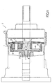
- Fig. 1 is a partially sectional view indicating a planetary gearing device 1 including a hollow shaft manufactured in a method of the present invention.
- the planetary gearing device 1 is usually provided within an automatic speed change gear box 2 of a motor vehicle.
- the automatic speed change gear box 2 has an input shaft 3 serving as an example of a hollow shaft having a flange at one end thereof.
- the rotation of the input shaft 3 is transmitted through the planetary gearing device 1 to an output shaft 4 serving as another example of a hollow shaft having a flange at one end thereof.
- a flange 5 is formed at one end (output side) of the input shaft (hollow shaft) 3.
- An internal gear 6 is provided around the outer periphery surface of the flange 5.
- the output shaft 4 (hollow shaft) is coaxially connected with the output side of the input shaft 3.
- a support shaft 8 is protrudingly provided on the output side of the input shaft 3 by means of a bearing 7 so that support shaft 8 is freely rotatable.
- a flange 9 serving as a carrier for planetary gears is provided in the vicinity of the support shaft 8.
- reference numeral 10 is used to represent a planetary gear supported by a carrier shaft 11 fixed on the flange 9. The planetary gear 10 is engaged with the internal gear 6 and a sun gear 12 supported on the output shaft 4.
- a method of manufacturing a hollow shaft having a flange at one end thereof (such as the input shaft 3 and the output shaft 4 used in the planetary gearing device 1) will be described in the following, with reference to Figs. 2 to 6.
- Fig. 2 is a longitudinally sectional view indicating the output shaft 4 manufactured in the method of the present invention.
- the output shaft 4 has a plate-like flange member A (including a support shaft 8 and a flange 9) and a hollow shaft member B.
- the plate-like flange member A and the hollow shaft member B are formed separately in different processes, and then combined together by shear spinning treatment so as to form an integral body.
- Fig. 3A is a partially sectional view indicating the plate-like flange member A.
- the plate-like flange member A has the support shaft 8 formed on one side of the flange 9, an axial projection 13 formed on the other side of the flange 9.
- the formation of the support shaft 8 and the axial projection 13 may be accomplished by a forging treatment such as by precision pressing treatment.
- the axial projection 13 has a constricted portion 13a formed by virtue of machining (cutting) treatment.
- Fig. 3B is a longitudinally sectional view indicating a hollow shaft member B.
- the hollow shaft member B is formed by a steel pipe having an internal diameter capable of engaging around the axial projection 13 of the plate-like flange member A.
- Fig. 4 is a longitudinally sectional view indicating a process in which the plate-like member A is combined with the hollow shaft member B.
- the plate-like member A is at first clamped in a first clamp apparatus 14a with the axial projection 13 positioned on the outside of the clamp apparatus 14a.
- the hollow shaft member B is engaged around the axial projection 13 of the plate-like flange member A.
- a mandrel 15 is inserted into the hollow shaft member B, so as to clamp the end portions of both the hollow shaft member B and the mandrel 15 on a second clamp apparatus 14b which is located opposite to the first clamp apparatus 14a.
- the front portion of the mandrel 15 has a diameter smaller than that of the axial projection 13 of the plate-like flange member A.
- a spinning roll 16 is used to perform a shear spinning treatment on the hollow shaft member B from its rear end to its front end (from the right to the left in the drawing).
- the hollow shaft member B will be deformed and thus reduced in its external diameter along the shape of the mandrel 15, as shown in Fig. 5.
- the front end of the hollow shaft member B may be plastically deformed to engage into the constricted portion 13a of the axial projection 13 of the plate-like flange member A.
- the axial projection 13 of the plate-like flange member A is also plastically deformed so as to enter the internal space of the hollow shaft member B, thereby completing a desired connection of the plate-like flange member A with the hollow shaft member B by means of caulking combination, followed by a predetermined machining treatment and a predetermined heating treatment.
- the axial projection 13 of the plate-like flange member A is also allowed to have a serration structure 13b formed around the outer periphery surface of the front portion of the axial projection 13. In this manner, it is sure to obtain a stronger combination of the plate-like flange member A with the hollow shaft member B, so as to prevent an undesired rotation of the plate-like flange member A.
- the second clamp apparatus 14b is caused to press the hollow shaft member B so that the second clamp apparatus 14b itself moves towards the first clamp 14a, with the moving amount corresponding to a plastic deforming amount of the hollow shaft member B.
- the thickness of the hollow shaft member B will change slightly corresponding to an actual pressing force and an actually moved amount of the second clamp apparatus 14b.
- the input shaft 3 shown in Fig. 7 includes a flange portion a and a hollow shaft portion b integrally formed with the flange portion a .
- the flange portion a of the input shaft 3 is fixed with the internal gear 6, in a manner shown in Fig. 1.
- Fig. 8 is an explanatory view indicating a condition in which a steel pipe section 19 having a predetermined diameter is clamped at both ends thereof by a movable die 17 and a fixed die 18 (which are arranged facing each other).
- the movable die 17 has a shoulder 17a and the fixed die 18 has a shoulder 18a, so that the outer surface of the steel pipe section 19 may be engaged by the shoulders 17a and 18a.
- one of the dies, such as the movable die 17 is provided with a mandrel 20 passing through the center thereof.
- the mandrel 20 has an outer diameter which is exactly equal to an inner diameter of the hollow portion of the input shaft 3.
- the fixed die 18 is formed with an internal hole 21 engageable by the mandrel 20. In this way, the movable die 17 may be moved by an NC-controlled pressing force so that the die 17 can move towards the fixed die 18.
- a spinning roll 22 is employed to carry out a shear spinning treatment on the outer surface of the steel pipe section 19 from one end thereof along its entire length, so that the steel pipe section 19 is deformed and thus reduced in its diameter, while the other end of the steel pipe section 19 is bent outwardly in its radial direction so as to be enlarged at this end.
- the movable die 17 is caused to move towards the fixed die 18, thereby pressing one end of the steel pipe section 19 so as to promote the above described deformation of the pipe section.
- an intermediate product of a desired input shaft 3 which includes a flange portion a having an outer diameter equal to the inner diameter of the shoulder portion 18a of the fixed die 18, also includes a hollow shaft portion b having an inner diameter equal to the outer diameter of the mandrel 20.
- a predetermined machining treatment is performed.
- an internal gear 6 is attached on to the outer periphery surface of the flange portion a by virtue of supercurrent discharge combination, followed by a predetermined heating treatment.
- a thickness of the flange portion a and a thickness of the hollow shaft portion b may be controlled in view of the length and thickness of the steel pipe sect ion 19 and in accordance with a pressing force and a moving amount of the movable die 17.
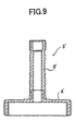
- Fig. 9 is a sectional view indicating, as another embodiment of the present invention, a modified input shaft 3' having a plate-like flange member A' (including an integrally formed internal gear 6) and a hollow shaft member B'.
- the modified input shaft 3' may be manufactured in the same method for manufacturing the above output shaft 4.
- the plate-like flange member A' way be prepared by machining treatment on a steel material, with the internal gear 6 integrally formed within the internal wall of the flange member.
- an axial projection 13 having a constricted portion 13a is formed at the center of the plate-like flange member A'.
- the axial projection 13 of the plate-like flange member A' is then engaged into the frond end (having a smaller internal diameter) of the hollow shaft member B'.
- a shear spinning treatment is carried out on the outer periphery surface of the hollow shaft member B', so that the hollow shaft member B' is deformed and thus reduced in its outer diameter.
- the axial projection 13 of the plate-like flange member A' may be combined with the hollow shaft member B' through a plastic working treatment by virtue of a caulking combination.
- each of the hollow shafts 3, 3' may be produced without forming the support shaft 8 on the plate-like flange member A or A'.
- each of the plate-like flange members A, A' and the flange portion a should not be limited to a plate-like shape, but is allowed to be formed with ribs or is entirely formed into a tray-like member.
- various materials forming different parts of the above hollow shafts are required to have a sufficient ductility (without being broken or forming any cracks) even under a condition in which they are subjected to a highly severe plastic working treatment. Further, various materials forming different parts of the above hollow shafts are required to have sufficient strength and hardness after a predetermined heating treatment.
- the inventors of the present invention have found some useful materials which can be suitably used to form different parts of the above hollow shafts.
- the newly found materials when in use, can reasonably reduce an amount of ferrite-enhancing elements such as Si and Mn contained therein, so as to reduce a deformation resistance during plastic working treatment. Further, the newly found materials are found to be capable of ensuring a desired hardenability.
- composition of a test steel used in the method of the present invention and the composition of SCr420 (chrome steel) used in a prior art are shown in Table 1.
- the ranges of various components contained in the steel materials suitable for use in the present invention may be concluded as follows. Namely, they are allowed to contain 0.2 - 0.6 wt% of C, 0.01 - 0.1 wt% of Si, 0.05 - 0.5 wt% of Mn, 0.001 - 0.01 wt% of B, 0.01 - 0.1 wt% of Ti or Nb, trace quantity of P and S, with the balance being Fe.
- an upper limit for the content of C contained in the steel materials used in the present invention is 0.6%.
- Si and Mn are controlled within their allowable ranges 0.01 - 0.1% and 0.05 - 0.5%, it is allowed to ensure a high ductility for the matrix of the steel materials, making it possible for the steel materials to contain C in a content as high as 0.6% (such kind of C content was not allowable in a prior art since a steel material containing C content of 0.6% in a conventional material was not allowed to receive a plastic working treatment).
- the ductility of a steel material will be improved still further if it does not contain Cr. Further, when C content is 0.2 to 0.35, it is allowed to perform a more complex plastic working treatment on a steel material. In addition, if a trace quantity of B is added, it is possible to remarkably improve the hardenability (heating treatment) of a steel material without hamperring its plastic workability.
- a plate-like flange member may be firmly attached to the front end of a hollow shaft member through a plastic working treatment by virtue of caulking combination.
- a plastic working treatment since the formation of the outer periphery surface and the internal surface of a hollow shaft member may be generally completed by virtue of a plastic working treatment, it is allowed to reduce operation steps involved in machining treatment and welding treatment which are usually carried out after the combination of the plate-like flange member with the hollow shaft member.
- the steel materials used in the present invention can stand a complex plastic working treatment, it is sure to obtain a desired strength and a desired hardness upon a heating treatment such as a quenching (hardening) treatment.
Landscapes
- Engineering & Computer Science (AREA)
- Mechanical Engineering (AREA)
- Shaping Metal By Deep-Drawing, Or The Like (AREA)
- Heat Treatment Of Steel (AREA)
- Shafts, Cranks, Connecting Bars, And Related Bearings (AREA)
Abstract
Description
- The present invention relates to a method of manufacturing a hollow shaft having a flange at one end thereof.
- A hollow shaft to which the present invention relates is often used as an output shaft in a planetary gearing device of a speed change gear box in a motor vehicle. Such kind of hollow shaft is usually manufactured by engaging a flange member with a hollow shaft member through plastic working treatment by virtue of caulking combination.
- Japanese Unexamined Patent Publication No. 58-100926 has disclosed a shaft manufacturing method in which a ring-like member is integrally formed at one end of a hollow shaft through plastic working treatment. In detail, an end portion of a cylindrical work piece engaged with a ring-like member is bent backwardly, so that the cylindrical work piece and the ring-like member may be firmly fixed together by virtue of caulking combination.
- Further, Japanese Unexamined Patent Publication No. 10-156450 has disclosed another shaft manufacturing method in which a ring-like member is engaged at one end of a hollow work piece, an outer periphery portion of the hollow work piece protruding beyond the ring-like member is bent towards the ring-like member, so that the ring-like member and the hollow work piece may be firmly fixed together by virtue of caulking combination.
- However, each of the above manufacturing methods requires that part of a hollow work piece protruding beyond a ring-like member (engaged with the hollow work piece) is subjected to a plastic working treatment so that the ring-like member may be pressed in the axial direction so as to be fixed in the hollow work piece. Although each of these methods is proved to be effective in securing a ring-like member (having a predetermined thickness in its axial direction) on to a hollow shaft with a predetermined strength, none of them has been provided to be effective in firmly securing a plate-like member onto a hollow shaft by virtue of caulking combination.
- The present invention has been accomplished in view of the above problem, its object is to provide a method in which a plate-like flange member may be firmly secured at the front end of a hollow shaft member through a plastic working treatment by virtue of caulking combination, so as to manufacture a hollow shaft having a flange at one end thereof.
- According to the present invention, there is provided a method of manufacturing a hollow shaft having a flange at one end thereof, said method comprising the steps of: preparing a plate-like flange member having an axial projection including a constricted portion on one side thereof; preparing a hollow shaft member having an elongate internal space arranged in the axial direction thereof; engaging the axial projection of the plate-like flange member into a front end portion of the hollow shaft member and at the same time inserting a mandrel into the hollow shaft member; pressing the hollow shaft member in its axial direction towards the plate-like flange member while performing a shear spinning treatment on the outer periphery surface of the hollow shaft member so as to reduce the size of the hollow shaft member in its radial direction; engaging the front portion of the hollow shaft member with the constricted portion of the axial projection of the plate-like flange member by virtue of caulking combination.
- In one aspect of the present invention, a front end portion of the axial projection of the plate-like flange member has a turning-prevention structure such as a serration structure formed on its outer periphery surface.
- In another aspect of the present invention, the plate-like flange member and the hollow shaft member, which are to be engaged with each other by virtue of caulking combination, are made of a material containing 0.2 - 0.6 wt% of C, 0.01 - 0.1 wt% of Si, 0.05 - 0.5 wt% of Mn, 0.001 - 0.01 wt% of B, 0.01 - 0. 1 wt% of Ti or Nb, with the balance being Fe, and are subjected to a heating treatment upon being combined into an integral body.
- With the use of the present invention, when the axial projection of the plate-like flange member is engaged into the front portion of the hollow shaft member by virtue of caulking combination, the front portion of the hollow shaft member may be partially combined into the constricted portion of the axial projection, thereby effecting an extremely strong caulking combination of the plate-like shaft member with the hollow shaft member.
- Further, if a front end portion of the axial projection of the plate-like flange member has a turning-prevention structure such as a serration structure formed on its outer periphery surface, it is sure to obtain a further strong combination of the two members.
- Moreover, since the plate-like flange member and the hollow shaft member are made of a material containing only a reduced amount of Si and Mn, it is allowed to ensure an improved ductility even if they contain a relatively large amount of C, thereby allowing a desired plastic working treatment on these members without causing any cracks.
- The above objects and features of the present invention will become better understood from the following description with reference to the accompanying drawings.
-
- Fig. 1 is a partially sectional side view illustrating an example of a planetary gearing device.
- Fig. 2 is a longitudinally sectional view indicating a hollow shaft (output shaft) made according to the present invention for use in the planetary gearing device of Fig. 1.
- Fig. 3A is a sectional view indicating a plate-like flange member forming a part of a hollow shaft made according to the present invention.
- Fig. 3B is a sectional view indicating a hollow shaft member forming a part of a hollow shaft made according to the present invention.
- Fig. 4 is an explanatory view indicating a process for combining together the hollow shaft member and the plate-like flange member.
- Fig. 5 is an explanatory view indicating a process for combining together the hollow shaft member and the plate-like flange member.
- Fig. 6 is a partially sectional view indicating another example of a plate-like flange member.
- Fig. 7 is a sectional view indicating an input hollow shaft integrally formed with a flange at one end thereof.
- Fig. 8 is an explanatory view indicating a process of performing a plastic working treatment for obtaining an input hollow shaft integrally formed with a flange at one end thereof.
- Fig. 9 is a sectional view indicating an input hollow shaft formed by a hollow shaft member and a plate-like flange member (including an internal gear formed within the flange member) manufactured in a method according to the present invention.
- Fig. 10A is a sectional view indicating a plate-like flange member containing an internal gear formed within the flange member.
- Fig. 10B is a sectional view indicating a hollow shaft member.
-
- One embodiment of the present invention will be described in the following with reference to the accompanying drawings.
- Fig. 1 is a partially sectional view indicating a planetary gearing device 1 including a hollow shaft manufactured in a method of the present invention. The planetary gearing device 1 is usually provided within an automatic speed
change gear box 2 of a motor vehicle. The automatic speedchange gear box 2 has aninput shaft 3 serving as an example of a hollow shaft having a flange at one end thereof. The rotation of theinput shaft 3 is transmitted through the planetary gearing device 1 to an output shaft 4 serving as another example of a hollow shaft having a flange at one end thereof. - As shown in Fig. 1, a
flange 5 is formed at one end (output side) of the input shaft (hollow shaft) 3. Aninternal gear 6 is provided around the outer periphery surface of theflange 5. On the other hand, the output shaft 4 (hollow shaft) is coaxially connected with the output side of theinput shaft 3. Asupport shaft 8 is protrudingly provided on the output side of theinput shaft 3 by means of abearing 7 so thatsupport shaft 8 is freely rotatable. Further, aflange 9 serving as a carrier for planetary gears is provided in the vicinity of thesupport shaft 8. Here,reference numeral 10 is used to represent a planetary gear supported by a carrier shaft 11 fixed on theflange 9. Theplanetary gear 10 is engaged with theinternal gear 6 and asun gear 12 supported on the output shaft 4. - A method of manufacturing a hollow shaft having a flange at one end thereof (such as the
input shaft 3 and the output shaft 4 used in the planetary gearing device 1) will be described in the following, with reference to Figs. 2 to 6. - Fig. 2 is a longitudinally sectional view indicating the output shaft 4 manufactured in the method of the present invention. As shown in Fig. 2, the output shaft 4 has a plate-like flange member A (including a
support shaft 8 and a flange 9) and a hollow shaft member B. At first, the plate-like flange member A and the hollow shaft member B are formed separately in different processes, and then combined together by shear spinning treatment so as to form an integral body. - Fig. 3A is a partially sectional view indicating the plate-like flange member A. As shown in Fig. 3A, the plate-like flange member A has the
support shaft 8 formed on one side of theflange 9, anaxial projection 13 formed on the other side of theflange 9. The formation of thesupport shaft 8 and theaxial projection 13 may be accomplished by a forging treatment such as by precision pressing treatment. Further, theaxial projection 13 has a constricted portion 13a formed by virtue of machining (cutting) treatment. - Fig. 3B is a longitudinally sectional view indicating a hollow shaft member B. In detail, the hollow shaft member B is formed by a steel pipe having an internal diameter capable of engaging around the
axial projection 13 of the plate-like flange member A. - Fig. 4 is a longitudinally sectional view indicating a process in which the plate-like member A is combined with the hollow shaft member B. As shown in Fig. 4, the plate-like member A is at first clamped in a first clamp apparatus 14a with the
axial projection 13 positioned on the outside of the clamp apparatus 14a. Then, the hollow shaft member B is engaged around theaxial projection 13 of the plate-like flange member A. meanwhile, amandrel 15 is inserted into the hollow shaft member B, so as to clamp the end portions of both the hollow shaft member B and themandrel 15 on asecond clamp apparatus 14b which is located opposite to the first clamp apparatus 14a. Here, the front portion of themandrel 15 has a diameter smaller than that of theaxial projection 13 of the plate-like flange member A. - Subsequently, a
spinning roll 16 is used to perform a shear spinning treatment on the hollow shaft member B from its rear end to its front end (from the right to the left in the drawing). As a result, the hollow shaft member B will be deformed and thus reduced in its external diameter along the shape of themandrel 15, as shown in Fig. 5. In this way, the front end of the hollow shaft member B may be plastically deformed to engage into the constricted portion 13a of theaxial projection 13 of the plate-like flange member A. Meanwhile, theaxial projection 13 of the plate-like flange member A is also plastically deformed so as to enter the internal space of the hollow shaft member B, thereby completing a desired connection of the plate-like flange member A with the hollow shaft member B by means of caulking combination, followed by a predetermined machining treatment and a predetermined heating treatment. - On the other hand, as shown in Fig. 6, the
axial projection 13 of the plate-like flange member A is also allowed to have aserration structure 13b formed around the outer periphery surface of the front portion of theaxial projection 13. In this manner, it is sure to obtain a stronger combination of the plate-like flange member A with the hollow shaft member B, so as to prevent an undesired rotation of the plate-like flange member A. - In the above process, the
second clamp apparatus 14b is caused to press the hollow shaft member B so that thesecond clamp apparatus 14b itself moves towards the first clamp 14a, with the moving amount corresponding to a plastic deforming amount of the hollow shaft member B. At this time, the thickness of the hollow shaft member B will change slightly corresponding to an actual pressing force and an actually moved amount of thesecond clamp apparatus 14b. - A method of manufacturing the
input shaft 3 shown in Fig. 7 will be described in the following with reference to Figs. 8 to 10. As shown in Fig. 7, theinput shaft 3 includes a flange portion a and a hollow shaft portion b integrally formed with the flange portion a. The flange portion a of theinput shaft 3 is fixed with theinternal gear 6, in a manner shown in Fig. 1. - Fig. 8 is an explanatory view indicating a condition in which a
steel pipe section 19 having a predetermined diameter is clamped at both ends thereof by amovable die 17 and a fixed die 18 (which are arranged facing each other). In detail, themovable die 17 has a shoulder 17a and the fixeddie 18 has a shoulder 18a, so that the outer surface of thesteel pipe section 19 may be engaged by the shoulders 17a and 18a. In more detail, one of the dies, such as themovable die 17 is provided with amandrel 20 passing through the center thereof. In fact, themandrel 20 has an outer diameter which is exactly equal to an inner diameter of the hollow portion of theinput shaft 3. The fixed die 18 is formed with aninternal hole 21 engageable by themandrel 20. In this way, themovable die 17 may be moved by an NC-controlled pressing force so that the die 17 can move towards the fixeddie 18. - After the
steel pipe section 19 has been clamped between themovable die 17 and the fixeddie 18, a spinningroll 22 is employed to carry out a shear spinning treatment on the outer surface of thesteel pipe section 19 from one end thereof along its entire length, so that thesteel pipe section 19 is deformed and thus reduced in its diameter, while the other end of thesteel pipe section 19 is bent outwardly in its radial direction so as to be enlarged at this end. At this moment, effected by an NC-controlled pressing force and in accordance with a predetermined moving amount, themovable die 17 is caused to move towards the fixeddie 18, thereby pressing one end of thesteel pipe section 19 so as to promote the above described deformation of the pipe section. - In this way, an intermediate product of a desired
input shaft 3 can be formed which includes a flange portion a having an outer diameter equal to the inner diameter of the shoulder portion 18a of the fixeddie 18, also includes a hollow shaft portion b having an inner diameter equal to the outer diameter of themandrel 20. Subsequently, a predetermined machining treatment is performed. Afterwards, aninternal gear 6 is attached on to the outer periphery surface of the flange portion a by virtue of supercurrent discharge combination, followed by a predetermined heating treatment. - In the above manufacturing process for forming the intermediate product of a desired
input shaft 3, a thickness of the flange portion a and a thickness of the hollow shaft portion b may be controlled in view of the length and thickness of the steelpipe sect ion 19 and in accordance with a pressing force and a moving amount of themovable die 17. - Fig. 9 is a sectional view indicating, as another embodiment of the present invention, a modified input shaft 3' having a plate-like flange member A' (including an integrally formed internal gear 6) and a hollow shaft member B'. In fact, the modified input shaft 3' may be manufactured in the same method for manufacturing the above output shaft 4.
- Namely, as shown in Fig. 10A, the plate-like flange member A' way be prepared by machining treatment on a steel material, with the
internal gear 6 integrally formed within the internal wall of the flange member. At this time, anaxial projection 13 having a constricted portion 13a is formed at the center of the plate-like flange member A'. Theaxial projection 13 of the plate-like flange member A' is then engaged into the frond end (having a smaller internal diameter) of the hollow shaft member B'. Afterwards, in the same method for manufacturing the output shaft 4, a shear spinning treatment is carried out on the outer periphery surface of the hollow shaft member B', so that the hollow shaft member B' is deformed and thus reduced in its outer diameter. In this way, theaxial projection 13 of the plate-like flange member A' may be combined with the hollow shaft member B' through a plastic working treatment by virtue of a caulking combination. - However, in any of the above embodiments, it is also possible that each of the
hollow shafts 3, 3' may be produced without forming thesupport shaft 8 on the plate-like flange member A or A'. Further, each of the plate-like flange members A, A' and the flange portion a should not be limited to a plate-like shape, but is allowed to be formed with ribs or is entirely formed into a tray-like member. - When using the manufacturing methods described in the above embodiments, various materials forming different parts of the above hollow shafts are required to have a sufficient ductility (without being broken or forming any cracks) even under a condition in which they are subjected to a highly severe plastic working treatment. Further, various materials forming different parts of the above hollow shafts are required to have sufficient strength and hardness after a predetermined heating treatment.
- In addition, the inventors of the present invention have found some useful materials which can be suitably used to form different parts of the above hollow shafts. The newly found materials, when in use, can reasonably reduce an amount of ferrite-enhancing elements such as Si and Mn contained therein, so as to reduce a deformation resistance during plastic working treatment. Further, the newly found materials are found to be capable of ensuring a desired hardenability.
- The composition of a test steel used in the method of the present invention and the composition of SCr420 (chrome steel) used in a prior art are shown in Table 1.
Chemical Composition % Element C Si Mn P S Cr B Ti or Nb Test Steel 0.20 0.08 0.38 0.02 0.02 - 0.002 0.05 SCr420 0.20 0.2 0.80 0.02 0.02 1.10 - - - It has been found that when the above test steel was used to form the plate-like flange member A shown in Fig. 3A and the hollow shaft member B shown in Fig. 3B, and when a shear spinning treatment was conducted on them, there were no cracks occurring thereon, thereby exhibiting a sufficient ductility. Then, upon a machining treatment and a high frequency hardening treatment, a hollow shaft having a flange at one end thereof was thus obtained which had a hardness of HcR 55 to 65, thus satisfying a predetermined standard.
- The ranges of various components contained in the steel materials suitable for use in the present invention may be concluded as follows. Namely, they are allowed to contain 0.2 - 0.6 wt% of C, 0.01 - 0.1 wt% of Si, 0.05 - 0.5 wt% of Mn, 0.001 - 0.01 wt% of B, 0.01 - 0.1 wt% of Ti or Nb, trace quantity of P and S, with the balance being Fe.
- As indicated in the above, an upper limit for the content of C contained in the steel materials used in the present invention is 0.6%. Under such a condition, if Si and Mn are controlled within their allowable ranges 0.01 - 0.1% and 0.05 - 0.5%, it is allowed to ensure a high ductility for the matrix of the steel materials, making it possible for the steel materials to contain C in a content as high as 0.6% (such kind of C content was not allowable in a prior art since a steel material containing C content of 0.6% in a conventional material was not allowed to receive a plastic working treatment).
- On the other hand, the ductility of a steel material will be improved still further if it does not contain Cr. Further, when C content is 0.2 to 0.35, it is allowed to perform a more complex plastic working treatment on a steel material. In addition, if a trace quantity of B is added, it is possible to remarkably improve the hardenability (heating treatment) of a steel material without hamperring its plastic workability.
- As may be understood from the above description, with the use of the present invention, it is allowed to obtain at least the following advantages.
- Namely, a plate-like flange member may be firmly attached to the front end of a hollow shaft member through a plastic working treatment by virtue of caulking combination. In this way, since the formation of the outer periphery surface and the internal surface of a hollow shaft member may be generally completed by virtue of a plastic working treatment, it is allowed to reduce operation steps involved in machining treatment and welding treatment which are usually carried out after the combination of the plate-like flange member with the hollow shaft member.
- Further, since the steel materials used in the present invention can stand a complex plastic working treatment, it is sure to obtain a desired strength and a desired hardness upon a heating treatment such as a quenching (hardening) treatment.
- While the presently preferred embodiments of the this invention have been shown and described above, it is to be understood that these disclosures are for the purpose of illustration and that various changes and modifications may be made without departing from the scope of the invention as set forth in the appended claims.
Claims (3)
- A method of manufacturing a hollow shaft having a flange at one end thereof, said method comprising the steps of:preparing a plate-like flange member having an axial projection including a constricted portion on one side thereof;preparing a hollow shaft member having an elongate internal space arranged in the axial direction thereof;engaging the axial projection of the plate-like flange member into a front end portion of the hollow shaft member and at the same time inserting a mandrel into the hollow shaft member;pressing the hollow shaft member in its axial direction towards the plate-like flange member while performing a shear spinning treatment on the outer periphery surface of the hollow shaft member so as to reduce the size of the hollow shaft member in its radial direction;engaging the front portion of the hollow shaft member with the constricted portion of the axial projection of the plate-like flange member by virtue of caulking combination.
- The method according to claim 1, wherein a front end portion of the axial projection of the plate-like flange member has a turning-prevention structure such as a serration structure formed on its outer periphery surface.
- The method according to claim 1 or 2, wherein the plate-like flange member and the hollow shaft member, which are to be engaged with each other by virtue of caulking combination, are made of a material containing 0.2 - 0.6 wt% of C, 0.01 - 0.1 wt% of Si, 0.05 - 0.5 wt% of Mn, 0.001 - 0.01 wt% of B, 0.01 - 0.1 wt% of Ti or Nb, with the balance being Fe, and are subjected to a heating treatment upon being combined into an integral body.
Applications Claiming Priority (2)
| Application Number | Priority Date | Filing Date | Title |
|---|---|---|---|
| JP11185542A JP2001009546A (en) | 1999-06-30 | 1999-06-30 | Method for manufacturing hollow shaft having flange at one end |
| JP18554299 | 1999-06-30 |
Publications (2)
| Publication Number | Publication Date |
|---|---|
| EP1065016A1 true EP1065016A1 (en) | 2001-01-03 |
| EP1065016B1 EP1065016B1 (en) | 2002-11-27 |
Family
ID=16172636
Family Applications (1)
| Application Number | Title | Priority Date | Filing Date |
|---|---|---|---|
| EP00113558A Expired - Lifetime EP1065016B1 (en) | 1999-06-30 | 2000-06-27 | Method of manufacturing a hollow shaft having a flange at one end thereof |
Country Status (4)
| Country | Link |
|---|---|
| US (2) | US6615476B1 (en) |
| EP (1) | EP1065016B1 (en) |
| JP (1) | JP2001009546A (en) |
| DE (1) | DE60000845T2 (en) |
Cited By (1)
| Publication number | Priority date | Publication date | Assignee | Title |
|---|---|---|---|---|
| EP2338620A1 (en) * | 2009-12-23 | 2011-06-29 | Leifeld Metal Spinning GmbH | Rotation-symmetrical component obtained by assembling two workpieces and method for its production |
Families Citing this family (8)
| Publication number | Priority date | Publication date | Assignee | Title |
|---|---|---|---|---|
| JP4354133B2 (en) * | 2001-08-10 | 2009-10-28 | カヤバ工業株式会社 | Cylinder processing method |
| JP2007175761A (en) * | 2005-12-28 | 2007-07-12 | Seiko Epson Corp | Shaft hole forming method |
| CA2757954A1 (en) | 2009-04-08 | 2010-10-14 | C & D Zodiac, Inc. | Vehicle seat tubing having variable wall thickness |
| WO2011133832A2 (en) | 2010-04-23 | 2011-10-27 | Douglas Machine Inc. | Apparatus and methods for producing shrink-wrap packaging |
| DE102016102707A1 (en) * | 2016-02-16 | 2017-08-17 | Recaro Aircraft Seating Gmbh & Co. Kg | Aircraft seat device |
| US11122741B2 (en) * | 2018-01-30 | 2021-09-21 | Cnh Industrial America Llc | Stalk roller assembly for an agricultural system |
| CN111256022A (en) * | 2020-01-15 | 2020-06-09 | 芜湖三联锻造股份有限公司 | Large thin-wall part with complex shape and manufacturing process thereof |
| US11318515B1 (en) | 2021-02-08 | 2022-05-03 | Sigma Corporation | Large diameter pipe rounding tool and method of use |
Citations (3)
| Publication number | Priority date | Publication date | Assignee | Title |
|---|---|---|---|---|
| JPS58135735A (en) * | 1982-02-05 | 1983-08-12 | Hitachi Ltd | How to fix a metal tube to a metal plate |
| DE19532519A1 (en) * | 1995-09-02 | 1997-03-06 | Leifeld Gmbh & Co | Forming method for metallic workpiece with rotational symmetry |
| US5771425A (en) * | 1991-08-02 | 1998-06-23 | Canon Kabushiki Kaisha | Mechanically fastened cylindrical engaging member for use in an image forming apparatus |
Family Cites Families (22)
| Publication number | Priority date | Publication date | Assignee | Title |
|---|---|---|---|---|
| US378058A (en) * | 1888-02-14 | Edgae peckham and emil la ass | ||
| US1442629A (en) * | 1922-01-10 | 1923-01-16 | American Hardware Corp | Knob and spindle construction |
| US2429293A (en) * | 1943-06-30 | 1947-10-21 | Parsons Engineering Corp | Method of making rollers |
| US2852843A (en) * | 1955-04-25 | 1958-09-23 | Aerojet General Co | Method of making metal joint |
| US3120206A (en) * | 1959-03-09 | 1964-02-04 | Lodge & Shipley Co | Metal working |
| US3189672A (en) * | 1959-12-15 | 1965-06-15 | Cambridge Thermionic Corp | Method of making an insulating mount with a terminal |
| US3367020A (en) * | 1965-05-19 | 1968-02-06 | Robert D. Watson | Method of preparing tubes of certain metals for subsequent joining by welding |
| US3699636A (en) * | 1971-02-17 | 1972-10-24 | Whittaker Corp | Metal bonding process |
| JPS5141618A (en) * | 1974-10-08 | 1976-04-08 | Nippon Steel Corp | Taiokurehakaiseino sugureta kochoryokuko oyobi sono seizohoho |
| US4056291A (en) * | 1975-08-04 | 1977-11-01 | Aspro, Inc. | Clutch housing and bearing assembly and method of making the same |
| DE3020749A1 (en) * | 1980-05-31 | 1981-12-10 | Fichtel & Sachs Ag, 8720 Schweinfurt | METHOD FOR PRODUCING PISTON RODS |
| JPS58100926A (en) | 1981-12-10 | 1983-06-15 | Showa Mfg Co Ltd | Roll tightening device for cylindrical members |
| JPS5954425A (en) * | 1982-09-20 | 1984-03-29 | Toshiba Mach Co Ltd | Method and device for rotation contour spinning |
| JPS5973136A (en) * | 1982-10-20 | 1984-04-25 | Kokan Kako Kk | Manufacturing method of hollow torsion bar with arm |
| JPH0270327A (en) * | 1988-09-01 | 1990-03-09 | Sumitomo Light Metal Ind Ltd | Spinning of pipe material |
| US5279688A (en) * | 1989-12-06 | 1994-01-18 | Daido Tokushuko Kabushiki Kaisha | Steel shaft material which is capable of being directly cut and induction hardened and a method for manufacturing the same |
| JPH068061A (en) * | 1992-06-24 | 1994-01-18 | Aichi Steel Works Ltd | Manufacture of metallic hollow structure body |
| DE4307994A1 (en) * | 1993-03-13 | 1994-09-15 | Teves Gmbh Alfred | Connection of a shaft or bolt with a crank lever of a wiper system |
| EP0725693B1 (en) * | 1993-12-09 | 1997-07-30 | Wf-Maschinenbau Und Blechformtechnik Gmbh & Co. Kg | Method for the non-cutting production of a transmission component hub |
| JPH07310118A (en) * | 1994-05-16 | 1995-11-28 | Daido Steel Co Ltd | Method for manufacturing case hardening steel suitable for cold working |
| JP3402562B2 (en) * | 1996-07-19 | 2003-05-06 | 大同特殊鋼株式会社 | Induction hardened parts |
| JPH10156450A (en) | 1996-11-27 | 1998-06-16 | Toyota Motor Corp | Caulking method and caulking device |
-
1999
- 1999-06-30 JP JP11185542A patent/JP2001009546A/en active Pending
-
2000
- 2000-06-26 US US09/602,672 patent/US6615476B1/en not_active Expired - Fee Related
- 2000-06-27 DE DE60000845T patent/DE60000845T2/en not_active Expired - Fee Related
- 2000-06-27 EP EP00113558A patent/EP1065016B1/en not_active Expired - Lifetime
-
2003
- 2003-06-20 US US10/601,270 patent/US6959479B2/en not_active Expired - Fee Related
Patent Citations (3)
| Publication number | Priority date | Publication date | Assignee | Title |
|---|---|---|---|---|
| JPS58135735A (en) * | 1982-02-05 | 1983-08-12 | Hitachi Ltd | How to fix a metal tube to a metal plate |
| US5771425A (en) * | 1991-08-02 | 1998-06-23 | Canon Kabushiki Kaisha | Mechanically fastened cylindrical engaging member for use in an image forming apparatus |
| DE19532519A1 (en) * | 1995-09-02 | 1997-03-06 | Leifeld Gmbh & Co | Forming method for metallic workpiece with rotational symmetry |
Cited By (1)
| Publication number | Priority date | Publication date | Assignee | Title |
|---|---|---|---|---|
| EP2338620A1 (en) * | 2009-12-23 | 2011-06-29 | Leifeld Metal Spinning GmbH | Rotation-symmetrical component obtained by assembling two workpieces and method for its production |
Also Published As
| Publication number | Publication date |
|---|---|
| DE60000845T2 (en) | 2003-08-28 |
| DE60000845D1 (en) | 2003-01-09 |
| US6959479B2 (en) | 2005-11-01 |
| JP2001009546A (en) | 2001-01-16 |
| EP1065016B1 (en) | 2002-11-27 |
| US6615476B1 (en) | 2003-09-09 |
| US20040083595A1 (en) | 2004-05-06 |
Similar Documents
| Publication | Publication Date | Title |
|---|---|---|
| JP3108710B2 (en) | Method of manufacturing gear for transmission | |
| EP2819794B1 (en) | Hollow drive shaft with flange and method for the production thereof | |
| EP1065016B1 (en) | Method of manufacturing a hollow shaft having a flange at one end thereof | |
| US8108996B2 (en) | Method of producing shafts | |
| US6161409A (en) | Process and device for manufacturing a gear part with outer teeth | |
| US7275407B2 (en) | Process for producing rotationally symmetrical components | |
| US5392517A (en) | Method of making a ring gear | |
| EP0493792A1 (en) | Method of manufacturing drive plate | |
| DE10240631A1 (en) | Thrust bearings and manufacturing process therefor | |
| DE19960582A1 (en) | Pressure rolling process for transmission components, involving clamping workpiece to tool, rotating it, partly separating sector with pressure roller and deforming | |
| EP0982087B1 (en) | A process for forming tubular components | |
| KR100271692B1 (en) | Non-cutting manufacturing method and apparatus for transmission parts hub | |
| DE3626425C2 (en) | ||
| DE102009001305B4 (en) | Method for producing a profile on a sheet metal part, device for carrying out the method and sheet metal part, which can be produced by the method | |
| DE10322752B4 (en) | Method for producing workpieces made of sheet metal | |
| JPH04322915A (en) | Method of manufacturing gear shaft | |
| US6675477B2 (en) | Method for manufacturing spool valve | |
| DE102006049146B4 (en) | Method for producing an assembly consisting of at least two interconnected sheet-metal parts | |
| EP1140387B1 (en) | Method for producing a rim for a pneumatic tyre | |
| DE19710193C2 (en) | Use of a cold rolling process to manufacture a yoke of a planetary gear starter | |
| JPS6358305B2 (en) | ||
| DE102013008658A1 (en) | Drive element, useful for motor vehicle, comprises hollow shaft, bevel gear, and first and second parts that are connected to each other by friction welding in weld zone and/or in weld seam and are made from different materials | |
| DE10148451C2 (en) | Process for producing a hollow body and preform | |
| JPH0755346B2 (en) | Manufacturing method of automobile components | |
| JP2002282991A (en) | Manufacturing method of stepped shaft |
Legal Events
| Date | Code | Title | Description |
|---|---|---|---|
| PUAI | Public reference made under article 153(3) epc to a published international application that has entered the european phase |
Free format text: ORIGINAL CODE: 0009012 |
|
| AK | Designated contracting states |
Kind code of ref document: A1 Designated state(s): DE GB |
|
| AX | Request for extension of the european patent |
Free format text: AL;LT;LV;MK;RO;SI |
|
| AKX | Designation fees paid | ||
| 17P | Request for examination filed |
Effective date: 20010615 |
|
| RBV | Designated contracting states (corrected) |
Designated state(s): DE GB |
|
| GRAG | Despatch of communication of intention to grant |
Free format text: ORIGINAL CODE: EPIDOS AGRA |
|
| 17Q | First examination report despatched |
Effective date: 20020204 |
|
| GRAG | Despatch of communication of intention to grant |
Free format text: ORIGINAL CODE: EPIDOS AGRA |
|
| GRAH | Despatch of communication of intention to grant a patent |
Free format text: ORIGINAL CODE: EPIDOS IGRA |
|
| GRAH | Despatch of communication of intention to grant a patent |
Free format text: ORIGINAL CODE: EPIDOS IGRA |
|
| GRAA | (expected) grant |
Free format text: ORIGINAL CODE: 0009210 |
|
| AK | Designated contracting states |
Kind code of ref document: B1 Designated state(s): DE GB |
|
| REG | Reference to a national code |
Ref country code: GB Ref legal event code: FG4D |
|
| REF | Corresponds to: |
Ref document number: 60000845 Country of ref document: DE Date of ref document: 20030109 |
|
| PLBE | No opposition filed within time limit |
Free format text: ORIGINAL CODE: 0009261 |
|
| STAA | Information on the status of an ep patent application or granted ep patent |
Free format text: STATUS: NO OPPOSITION FILED WITHIN TIME LIMIT |
|
| 26N | No opposition filed |
Effective date: 20030828 |
|
| PGFP | Annual fee paid to national office [announced via postgrant information from national office to epo] |
Ref country code: DE Payment date: 20080703 Year of fee payment: 9 |
|
| PGFP | Annual fee paid to national office [announced via postgrant information from national office to epo] |
Ref country code: GB Payment date: 20080702 Year of fee payment: 9 |
|
| GBPC | Gb: european patent ceased through non-payment of renewal fee |
Effective date: 20090627 |
|
| PG25 | Lapsed in a contracting state [announced via postgrant information from national office to epo] |
Ref country code: GB Free format text: LAPSE BECAUSE OF NON-PAYMENT OF DUE FEES Effective date: 20090627 |
|
| PG25 | Lapsed in a contracting state [announced via postgrant information from national office to epo] |
Ref country code: DE Free format text: LAPSE BECAUSE OF NON-PAYMENT OF DUE FEES Effective date: 20100101 |