EP1063911B1 - Automated beverage brewing system - Google Patents
Automated beverage brewing system Download PDFInfo
- Publication number
- EP1063911B1 EP1063911B1 EP99902364A EP99902364A EP1063911B1 EP 1063911 B1 EP1063911 B1 EP 1063911B1 EP 99902364 A EP99902364 A EP 99902364A EP 99902364 A EP99902364 A EP 99902364A EP 1063911 B1 EP1063911 B1 EP 1063911B1
- Authority
- EP
- European Patent Office
- Prior art keywords
- chamber
- liquid
- metering chamber
- controller
- cartridge
- Prior art date
- Legal status (The legal status is an assumption and is not a legal conclusion. Google has not performed a legal analysis and makes no representation as to the accuracy of the status listed.)
- Expired - Lifetime
Links
- 235000013361 beverage Nutrition 0.000 title claims abstract description 34
- 239000007788 liquid Substances 0.000 claims abstract description 50
- 239000000284 extract Substances 0.000 claims description 4
- 238000012545 processing Methods 0.000 claims description 3
- 238000010438 heat treatment Methods 0.000 claims 3
- XLYOFNOQVPJJNP-UHFFFAOYSA-N water Substances O XLYOFNOQVPJJNP-UHFFFAOYSA-N 0.000 description 28
- 238000012360 testing method Methods 0.000 description 17
- 229920001296 polysiloxane Polymers 0.000 description 4
- 239000000523 sample Substances 0.000 description 3
- 238000007664 blowing Methods 0.000 description 2
- 230000001934 delay Effects 0.000 description 2
- 230000000994 depressogenic effect Effects 0.000 description 2
- 239000006260 foam Substances 0.000 description 2
- 238000013022 venting Methods 0.000 description 2
- 241000233805 Phoenix Species 0.000 description 1
- 241001122767 Theaceae Species 0.000 description 1
- 238000007792 addition Methods 0.000 description 1
- 238000013124 brewing process Methods 0.000 description 1
- 239000012141 concentrate Substances 0.000 description 1
- 230000003111 delayed effect Effects 0.000 description 1
- 230000001419 dependent effect Effects 0.000 description 1
- 238000005516 engineering process Methods 0.000 description 1
- 229920002457 flexible plastic Polymers 0.000 description 1
- 239000012530 fluid Substances 0.000 description 1
- 230000005484 gravity Effects 0.000 description 1
- 238000003754 machining Methods 0.000 description 1
- 238000000034 method Methods 0.000 description 1
- 238000012544 monitoring process Methods 0.000 description 1
- 238000012354 overpressurization Methods 0.000 description 1
- 230000035515 penetration Effects 0.000 description 1
- 230000002572 peristaltic effect Effects 0.000 description 1
- 239000000843 powder Substances 0.000 description 1
- 230000004044 response Effects 0.000 description 1
- 238000011076 safety test Methods 0.000 description 1
- 238000012546 transfer Methods 0.000 description 1
Images




Classifications
-
- A—HUMAN NECESSITIES
- A47—FURNITURE; DOMESTIC ARTICLES OR APPLIANCES; COFFEE MILLS; SPICE MILLS; SUCTION CLEANERS IN GENERAL
- A47J—KITCHEN EQUIPMENT; COFFEE MILLS; SPICE MILLS; APPARATUS FOR MAKING BEVERAGES
- A47J31/00—Apparatus for making beverages
- A47J31/24—Coffee-making apparatus in which hot water is passed through the filter under pressure, i.e. in which the coffee grounds are extracted under pressure
- A47J31/34—Coffee-making apparatus in which hot water is passed through the filter under pressure, i.e. in which the coffee grounds are extracted under pressure with hot water under liquid pressure
- A47J31/36—Coffee-making apparatus in which hot water is passed through the filter under pressure, i.e. in which the coffee grounds are extracted under pressure with hot water under liquid pressure with mechanical pressure-producing means
- A47J31/3604—Coffee-making apparatus in which hot water is passed through the filter under pressure, i.e. in which the coffee grounds are extracted under pressure with hot water under liquid pressure with mechanical pressure-producing means with a mechanism arranged to move the brewing chamber between loading, infusing and ejecting stations
- A47J31/3623—Cartridges being employed
- A47J31/3633—Means to perform transfer from a loading position to an infusing position
-
- A—HUMAN NECESSITIES
- A47—FURNITURE; DOMESTIC ARTICLES OR APPLIANCES; COFFEE MILLS; SPICE MILLS; SUCTION CLEANERS IN GENERAL
- A47J—KITCHEN EQUIPMENT; COFFEE MILLS; SPICE MILLS; APPARATUS FOR MAKING BEVERAGES
- A47J31/00—Apparatus for making beverages
- A47J31/24—Coffee-making apparatus in which hot water is passed through the filter under pressure, i.e. in which the coffee grounds are extracted under pressure
- A47J31/32—Coffee-making apparatus in which hot water is passed through the filter under pressure, i.e. in which the coffee grounds are extracted under pressure with hot water under air pressure
-
- A—HUMAN NECESSITIES
- A47—FURNITURE; DOMESTIC ARTICLES OR APPLIANCES; COFFEE MILLS; SPICE MILLS; SUCTION CLEANERS IN GENERAL
- A47J—KITCHEN EQUIPMENT; COFFEE MILLS; SPICE MILLS; APPARATUS FOR MAKING BEVERAGES
- A47J31/00—Apparatus for making beverages
- A47J31/24—Coffee-making apparatus in which hot water is passed through the filter under pressure, i.e. in which the coffee grounds are extracted under pressure
- A47J31/34—Coffee-making apparatus in which hot water is passed through the filter under pressure, i.e. in which the coffee grounds are extracted under pressure with hot water under liquid pressure
- A47J31/36—Coffee-making apparatus in which hot water is passed through the filter under pressure, i.e. in which the coffee grounds are extracted under pressure with hot water under liquid pressure with mechanical pressure-producing means
- A47J31/3604—Coffee-making apparatus in which hot water is passed through the filter under pressure, i.e. in which the coffee grounds are extracted under pressure with hot water under liquid pressure with mechanical pressure-producing means with a mechanism arranged to move the brewing chamber between loading, infusing and ejecting stations
- A47J31/3623—Cartridges being employed
-
- A—HUMAN NECESSITIES
- A47—FURNITURE; DOMESTIC ARTICLES OR APPLIANCES; COFFEE MILLS; SPICE MILLS; SUCTION CLEANERS IN GENERAL
- A47J—KITCHEN EQUIPMENT; COFFEE MILLS; SPICE MILLS; APPARATUS FOR MAKING BEVERAGES
- A47J31/00—Apparatus for making beverages
- A47J31/24—Coffee-making apparatus in which hot water is passed through the filter under pressure, i.e. in which the coffee grounds are extracted under pressure
- A47J31/34—Coffee-making apparatus in which hot water is passed through the filter under pressure, i.e. in which the coffee grounds are extracted under pressure with hot water under liquid pressure
- A47J31/36—Coffee-making apparatus in which hot water is passed through the filter under pressure, i.e. in which the coffee grounds are extracted under pressure with hot water under liquid pressure with mechanical pressure-producing means
- A47J31/3604—Coffee-making apparatus in which hot water is passed through the filter under pressure, i.e. in which the coffee grounds are extracted under pressure with hot water under liquid pressure with mechanical pressure-producing means with a mechanism arranged to move the brewing chamber between loading, infusing and ejecting stations
- A47J31/3623—Cartridges being employed
- A47J31/3628—Perforating means therefor
Definitions
- This invention relates generally to a system for repeatedly delivering a predetermined volume of heated liquid and in particular to dispensing and brewing systems, more particularly to an improved apparatus for providing a brewed beverage.
- This invention relates generally to beverage dispensing and brewing systems, and in particular with an improved apparatus for provideng a brewed beverage.
- An object of the present invention is to provide an automated beverage brewing system for consistently dispensing a predetermined volume of liquid from a storage tank.
- the system uses compressed air to drive a predetermined amount of liquid from a metering chamber for use in preparing a brewed beverage.
- a beverage brewing system in one embodiment, includes a liquid storage tank and a metering chamber.
- the metering chamber is at least partially submerged beneath a standing level of liquid in the storage tank.
- the chamber includes a sealable liquid inlet port communicating with the interior of the storage tank beneath the standing level of liquid.
- the chamber also includes a liquid outlet port and an aperture that receives compressed air, wherein the compressed air forces a predetermined amount of liquid from the liquid output port of the chamber for use in preparing a brewed beverage.
- a pump provides the compressed air and a controller monitors a sensed pressure signal value indicative of the air pressure in the metering chamber. The controller commands the pump onto commence flow of the predetermined amount of liquid from the metering chamber.
- the controller then commands the pump off several seconds after detecting a drop in air pressure within the chamber, indicating that the predetermined amount of liquid has been delivered to the brewing chamber.
- the chamber is then vented to ambient pressure, which opens the sealable liquid inlet port and allows liquid to flow from the storage tank into the chamber.
- the sealable liquid inlet port automatically closes to complete the resupply of the metering chamber.
- the controller commands an electrically controllable vent valve to the open position.
- the present invention is specially adapted for use in, although not limited in application to, a brewing system 10 illustrated in FIG. 1.
- the dispensed liquid is water that is heated to a predetermined elevated temperature to brew beverages from extracts (e.g., coffee, tea, powders and concentrates) contained in disposable hermetically sealed cartridges.
- the brewing system consistently dispenses equal volumes of water 12 from a storage tank 14.
- a small metering chamber 16 is the primary dispensing component.
- the metering chamber 16 is at least partially submerged beneath the standing level of water 12 in the tank 14.
- a cover 18 overlies and hermetically seals both the tank and the metering chamber.
- the metering chamber 16 has an inlet port 20 on the bottom thereof to accommodate water inflow from the tank 14, a pneumatic port 22, and a third port 23 that accommodates penetration into the metering chamber of a discharge conduit 24 to a depth "d".
- a one way valve accommodates an inflow of water from the tank 14 into the metering chamber 16 through the inlet port 20.
- the one way valve comprises a silicone ball 26 sized to gravitationally seat in and seal the inlet port 20. As shown, the ball 26 is seated in a closed position to prevent outflow of water from the metering chamber 16 via the inlet port 20. As will hereinafter be explained, the ball 26 is adapted to be dislodged from the inlet opening by an inflow of water from the storage tank 14.
- the storage tank 14 receives water from a reservoir 27 via a fill conduit 28.
- An electrical float switch 29 is located in the reservoir 27 and provides a signal on a line 30 indicative of the water level in the reservoir.
- An air pump 31 (e.g., a diaphragm pump) provides compressed air into a conduit 32, which routes the compressed air through flow restrictor 33 and a check valve 34 and into the pneumatic port 22.
- the flow restrictor 33 provides smoother compressed air.
- a pressure sensor 36 monitors the pressure within the conduit 32 and provides a sensed pressure signal value indicative thereof on a line 38 to a system controller 40.
- the controller 40 also receives a sensed temperature signal on a line 42 from a temperature sensor 44 (e.g., a thermistor) that monitors water temperature in the storage tank 14.
- the controller 40 receives input signals from a brewer control panel 50 such as a start brewing signal on a line 52, and the reservoir water level signal on the line 30.
- the system also includes a brew valve 54, a vent valve 56 and a water shut-off valve 58.
- Each of these valves 54, 56 and 58 operate in open or closed states, in response to command signals from the controller 40.
- the system 10 further comprises a beverage cartridge holder 60 that cooperates with an axially moveable lid 62, which is responsive to a lid position command signal on a line 64 from the controller 40.
- the controller 40 receives various position signals on a line 66, that include lid position signals that are used to verify that the lid has moved to its commanded position.
- FIG. 2 is a pictorial illustration of a brew head assembly 70 comprising the beverage cartridge holder 60 and the axially moveable lid 62.
- the system 70 includes a slidable drawer 72 comprising side panels 74, 76 that each include a mounting hole (not shown), which together pivotally mount the beverage cartridge holder 60 to the slidable drawer 72.
- the drawer 72 slides along track assembles 78, 80.
- a drawer microswitch 79 provides a drawer position signal on the line 66 indicative of whether or not the drawer is in the closed position.
- the axially moveable lid 62 is manipulated by a linkage yoke 82 (partially shown), driven by an electric motor 84 through a pinion driven rack 85.
- the lid is axially guided along vertical side tracks 86, 87 between a ready position and a beverage brewing position. In the ready position the lid is axially positioned above and separated from the cartridge holder 60, assuming of course that the slidable drawer 72 is in the closed position.
- Microswitches 88, 89 detect if the lid is in the ready position or the beverage brewing position and provide the lid position signals on the line 66.
- the holder includes a chamber 90, and cartridge ejection arms 92, 94 that support and position a beverage cartridge (not shown) within the holder.
- FIG. 3A is a side view of the cartridge holder 60 and the lid 62.
- a beverage cartridge 96 (preferably disposable) has been inserted into the cartridge holder 60.
- a preferred beverage cartridge is disclosed in U.S. Patent 5,840,189, which is assigned to the assignee of the present invention and hereby incorporated by reference.
- a preferred cartridge holder is disclosed in co-pending application identified as Serial Number TBD, filed January 19, 1999 and entitled "Beverage Filter Cartridge Holder” , also assigned to the assignee of the present invention and incorporated by reference.
- the controller 40 monitors the pressure and temperature signals on the lines 38, 42 and the start brewing signal on the line 52 to control the pump 31, the tank heater 54 and various valves in the system. We shall now discuss the system control in more detail.
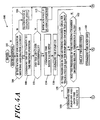
- FIGs. 4A and 4B are flow charts that together illustrate a brew cycle routine 100 performed by the controller 40 (FIG. 1) during a brewing cycle.
- the controller 40 is preferably a microcontroller (MCU) such as a model PIC16C72-4 manufactured by Microchip Technology, Inc. of Phoenix, Arizona.
- MCU microcontroller
- This microcontroller includes on chip program memory, RAM, a RISC CPU and an analog-to-digital converter (ADC).
- ADC analog-to-digital converter
- the steps illustrated in FIGs. 4A and 4B represent executable program instructions that are stored in the MCU program memory and periodically executed by the CPU.
- the routine 100 includes a test 102 that determines if the brewing process should begin. This test checks the state of the start brewing signal on the line 52 (FIG. 1). If the signal indicates that a user has not depressed the start brewing button, then the remaining steps of the routine 100 are not executed. However, if the start brewing signal indicates that the user has depressed the start brewing button, test 104 is performed to determine if the water temperature is hot enough for brewing. The test 104 checks the sensed temperature signal value on the line 42 and if the temperature is too low, then step 106 is executed to illuminate a status light (e.g., a yellow light) and the routine 100 is ended. If the water temperature is hot enough for brewing step 108 commands the lid 62 (FIG.
- a status light e.g., a yellow light
- the controller sends a lid command signal on the line 64 (FIG. 1) to the motor 84 (FIG. 2), which axially drives the lid 62 along the vertical side tracks 86, 87 (FIG. 1) from the ready position to the beverage brewing position.
- a lid command signal on the line 64 (FIG. 1) to the motor 84 (FIG. 2), which axially drives the lid 62 along the vertical side tracks 86, 87 (FIG. 1) from the ready position to the beverage brewing position.
- FIG. 3A illustrates the cartridge holder 60 populated with the cartridge 96, and the lid 62 in the ready position.
- FIG. 5A is a simplified cross sectional front view with the beverage cartridge 96 inserted into the holder 60, and the lid 40 in the ready position.
- the holder includes a housing 110 having an upwardly extending hollow piercing member 112 secured to a base surface 114.
- a slidable cartridge platform 116 having a bore 118 formed therein is coaxial with the upwardly extending piercing member 112, which allows the member 112 to extend through the slidable cartridge platform 116.
- the hollow piercing member includes a circular lip that rests on the periphery of a base surface opening 121, and an outwardly extending conduit 122 that passes through a base surface opening 121 and extends below the base surface 114.
- a resilient member 124 (e.g., a spiral spring) is operatively located between the base surface 114 and the slidable cartridge platform 116.
- a sidewall 126 extends axially from the base surface 114 to define the chamber 90 (FIG. 2) that is sized to receive the cartridge 96.
- the sidewall 126 includes first and second guide channels (not shown) that engage cartridge ejection arms 92, 94, respectively, allowing the slidable cartridge platform 116 to axially move within the chamber.
- the cartridge ejection arms 92, 94 are connected to the slidable cartridge platform 116, and have axial end surfaces 136, 138 that contact and support a radially outwardly protruding lip 140 of the cartridge 96.
- a pair of radially outwardly extending trunnions 142, 144 cooperate with holder mounting holes (not shown) in the side panels 74, 76 (FIG. 2) to pivotally support the holder.
- Pawls 146, 148 are used to position the holder 60 about the axis extending through the trunnions 142, 144.
- FIGs. 3B and 5B illustrate a side view and a simplified cross sectional view of the holder populated with the cartridge, and the lid in the beverage brewing position.
- an inclined surface 149 of a downward projecting pivot arm 150 that is attached to the lid contacts the pawl 148.
- the pivot arm 150 and its inclined surface 149 are preferably a flexible plastic allowing the pivot arm to bend slightly away as the surface 149 slides downwardly against the pawl.
- the inclined surface passes below the pawl 148 and the pivot arm flexes back.
- the lid then applies an axial positioning force to the radially outwardly protruding lip 140 of the cartridge, moving the slidable cartridge platform 116 deeper into the chamber and compressing the resilient member 124.
- the force applied by the lid 62 causes a downwardly projecting apertured probe 153 to pierce the top of the cartridge 96 establishing a flow inlet that provides a liquid (e.g., hot water) to the interior of the cartridge.
- the force also causes the hollow piercing member 112 to extend through the bore 118 and pierce a bottom surface of the cartridge, to provide an exit flow path for a brewed beverage through the slidable cartridge platform 116 and the base surface 114.
- a foam gasket 155 surrounds the downwardly projecting apertured probe 153.
- step 108 the controller performs a test 151 to determine if the lid has successfully moved into the beverage brewing position. This test is performed by checking the status of the lid position signals on the line 66 (FIG. 1) from the microswitches 88, 89 (FIG. 1). If the lid has not successfully closed, step 152 is executed to annunciate the fault/alarm condition and the routine 100 is ended. However, if the lid has closed successfully, step 154 commands the brew valve 54 (FIG. 1) to open and step 156 commands the pump 31 (FIG. 1) on.
- the pump 31 drives compressed air into the metering chamber 16
- the water in the metering chamber is driven into the discharge conduit 24 and passes through the brew valve 54 into the cartridge holder 60.
- the increased pressure within the metering chamber 16 firmly seats the silicone ball 26 over the inlet 20 to prevent flow from the storage tank 14 to the metering chamber 16.
- the water from the metering chamber enters the cartridge 96 through the downwardly projecting apertured probe 153, passes through beverage extract and a filter within the cartridge, and exits the cartridge 96 through the hollow piercing member 112.
- the controller performs a safety test 158 to monitor the sensed pressure signal value on the line 38 (FIG. 1), which is representative of the pressure in the metering chamber. If the pressure rises to more the 6 PSI above ambient pressure, then step 160 commands the pump off and the vent valve 56 (FIG. 1) to the open position in order to release the pressure in the metering chamber 16 (FIG. 1). The test 158 also checks if the pump has been on for more than a limit amount (e.g., one minute) and executes the step 160 if it has.
- a limit amount e.g., one minute
- test 162 is performed to determine if the air pressure in the metering chamber has dropped below a threshold value indicating that a predetermined amount of liquid (e.g., eight fluid ounces) has exited the metering chamber.
- This test 162 monitors the sensed pressure value on the line 38 (FIG. 1).
- the threshold value is preferably a fraction of the maximum sensed pressure during the brewing cycle.
- the threshold may be 75% of the maximum sensed pressure during the brewing cycle.
- the threshold may be a constant value.
- step 164 is performed to delay several seconds in order to blow residual liquid from the liquid flow path located between the metering chamber and the cartridge holder outlet.
- blowing out the flow path ensures that only hot water is used to brew, which is especially important if there is a substantial period between use.
- blowing out the flow path removes liquid from the used cartridge for cleaner disposal.
- the controller performs other tasks such as input signal processing, output signal processing, storage tank temperature control, reservoir water level control, and background and foreground built-in-tests.
- the delays may be implemented by hardware or software counters.
- Steps 166, 168 are then executed to command the pump off and close the brew valve 54 (FIG. 1). At this time the metering chamber is still pressurized and includes only a small amount of water that is located below the discharge conduit 24 (FIG. 1).
- Test 170 is performed to determine if the shut-off valve 58 (FIG. 1) is opened, indicating that the reservoir 27 (FIG. 1) is still being refilled from previous brewing cycles. If it is, then refilling of the metering chamber is delayed by step 172. Refilling the metering chamber begins when step 174 commands the vent valve 56 (FIG. 1) to open. This reduces the air pressure in the metering chamber to ambient pressure, causing the silicone ball 26 (FIG. 1) to be unseated and water to enter the chamber through the inlet 20 (FIG. 1). The water fills the metering chamber and the silicone ball gravitationally reseats in the liquid inlet. The reservoir 27 (FIG. 1) refills the storage tank 14 via the fill conduit 28.
- Step 176 is then performed to move the lid from the beverage brewing position to the ready position.
- FIG. 5C illustrates a transitional lid position as the lid moves from the brewing position to the ready position, illustrating the cartridge withdrawn from the hollow piercing member 112.
- the resilient member 124 expands causing the slidable cartridge platform 116 to move axially upward withdrawing the cartridge 96 from the hollow piercing member 112.
- the downward projecting pivot arm 150 engages the underside of the pawl 148 as the lid moves to the ready position.
- the pivot arm contacts the underside of the pawl 148 causing the holder to rapidly rotate about the trunnions.
- the other pawl 146 cooperates with stops (not shown) located on the sidewall 74 (FIG. 2) to limit the pivotal movement of the holder between the upright position and discharge positions (e.g., about 135 degrees of rotation).
- the pawl 146 strikes one of the stops abruptly stopping the rotation of the holder and ejecting the cartridge.
- this automatically removes the cartridge from the holder upon the completion of the brewing cycle.
- a plurality of projections 178 are located on the underside of the lid 62.
- the projections 178 may radially extend from the center of the underside of the lid.
- the foam gasket 155 also assists in separating the lid 62 from the top of the cartridge 96.
- step 180 is performed to delay several seconds to ensure there is enough time between opening of the venting valve in the step 174 and closing of the valve in step 182 for the metering chamber to refill.
- the drawer 22 (FIG. 1) is opened and a new cartridge is inserted into the holder.
- FIG. 6 is a flow chart of a built-in-test routine 200 periodically performed by the controller.
- the routine 200 includes a test 202 to determine if the heater 54 (FIG. 1) has been on for an excessive amount of time (e.g., twenty minutes). If it has, step 204 is performed to command the heater off, followed by step 206 to annunciate the fault/alarm condition. Otherwise, test 208 is performed to determined if the metering chamber 16 (FIG. 1) is over pressurized. If it is, then step 210 is performed to turn the pump off and open the vent valve followed by the step 206 to annunciate the fault/alarm condition. However, if over pressurization does not exist, test 212 checks if the shut-off valve 58 (FIG.
- the system 10 preferably includes a float type shut-off valve 220 that closes if the water level in the reservoir is too high. This valve is redundant with the electrically controllable shut-off valve 58 (FIG. 1), and this redundancy virtually eliminates single point failures from causing overfilling.
- the controller 40 also performs reservoir water level control by monitoring the reservoir water level signal on the line 30.
- the controller opens the shut-off valve 58 when the reservoir water level falls below a lower limit and closes the valve when the level is above an upper limit.
- a level sensor e.g., a float switch
- compressed air is used to drive the predetermined amount of liquid from the metering chamber.
- the present invention has been discussed in the context of an automated brewing system that includes a microcontroller, one of ordinary skill will recognize that there a number of different techniques for controlling the delivery of the compressed air to the metering chamber.
- a state machine may be used rather than a CPU.
- the controller may be an analog system rather than a digital controller.
- a pneumatic controller rather than an electronic controller may be used to control delivery and venting of the compressed air.
- the present invention is certainly not limited to the delay values, threshold values or brewing sizes discussed herein.
- the vent valve may be mechanically linked to the lid so the valve opens as the lid moves from the beverage brewing position to the ready position.
- the present invention may also operate in a "vending" environment. That is, as a vending machining, the system would not start brewing until money has been deposited or an account debited.
- test 104 (FIG. 4A) may check to ensure the required fee has been paid before brewing is allowed to start.
Landscapes
- Engineering & Computer Science (AREA)
- Food Science & Technology (AREA)
- Mechanical Engineering (AREA)
- Apparatus For Making Beverages (AREA)
- Tea And Coffee (AREA)
- Soy Sauces And Products Related Thereto (AREA)
- Distillation Of Fermentation Liquor, Processing Of Alcohols, Vinegar And Beer (AREA)
- Devices For Dispensing Beverages (AREA)
Abstract
Description
Claims (12)
- A system for repeatedly delivering a predetermined volume of heated liquid, said system comprising:characterized bya storage tank (14) containing a supply of liquid (12) ;a heater (54) for heating the supply of liquid (12) ;a metering chamber (16) at least partially submerged beneath the standing level of liquid (12) in said storage tank (14) ;an inlet (20) in said metering chamber (16) communicating with the interior of said storage tank (14) beneath said standing level;a one-way valve mechanism (26) for opening said inlet (20) to admit said predetermined volume of heated liquid (12) from said storage tank (14) into said chamber (16), and for closing said inlet (20) to prevent a reverse flow from said chamber (16) back into said tank (14) ;a discharge conduit (24) communicating with the interior of said chamber (16) ;a pump (31) that pneumatically pressurises the interior of said chamber (16) to an elevated pressure level to thereby exhaust said predetermined volume of heated liquid (12) from said chamber (16) via said discharge conduit (24),
means (36, 40, 56) responsive to said exhaustion of said predetermined volume of heated liquid (12) from said chamber (16), for relieving said elevated pressure to thereby accommodate a resupply of said predetermined volume of heated liquid from said tank (14) into said chamber (16). - The system of claim 1, wherein said means for relieving comprises:a sensor (36) that senses pressure in said metering chamber (16) and provides a sensed pressure signal value (38) indicative thereof; anda controller (40) that monitors said sensed pressure signal value (38) and turns said pump (31) off a predetermined time period after detecting a reduction in said sensed pressure signal value (38) below a threshold value indicating said predetermined volume of heated liquid (12) has been delivered through said discharge conduit (24).
- The system of claim 2, wherein said means for relieving further comprises a vent valve (56) having an inlet (22) in communication with the interior of said metering chamber (16), wherein said controller (40) commands said vent valve (56) to open after detecting said reduction in said sensed pressure signal value (38) below said threshold value.
- The system of claim 3, wherein said vent valve (56) is in communication with compressed air within said metering chamber (16), and wherein said controller (40) commands said vent valve (56) to open to vent said compressed air within said metering chamber (16) to ambient pressure.
- The system of any one of claims 2 to 4, wherein said controller (40) comprises a central processing unit.
- The system of any one of claims 1 to 5, further comprising:a holder (60) that holds and pierces a disposable cartridge (96) containing a beverage extract to establish a cartridge inlet and a cartridge outlet that together define a flow path through the beverage extract to provide a brewed beverage through said cartridge outlet, wherein said cartridge inlet receives said predetermined volume of heated liquid.
- The system of claim 6, further comprising:a temperature sensor (44) that senses the temperature of said supply of liquid (12) in said storage tank (14) and provides a sensed temperature signal value (42) indicative thereof, wherein said controller (40) monitors said sensed temperature signal value (42) and prevents said pump (31) from being turned on if said temperature signal value (42) is below a minimum brewing temperature value.
- The system of claim 1, wherein said means (36, 40, 56) for relieving comprises a vent valve (56) disposed to release said elevated pressure within said metering chamber (16) after exhausting said predetermined volume of heated liquid (12) from said metering chamber (16).
- The system of claim 7, wherein said controller (40) monitors said temperature signal value (42) and commands said heater (54) on if said sensed temperature signal value (42) drops below a lower heating threshold value and commands said heater off (54) if said sensed temperature signal value is greater than an upper heating threshold value.
- A system according to claim 6, wherein said metering chamber (16) is a sealed metering chamber,
and wherein said predetermined volume of heated liquid is received at said cartridge inlet from said discharge conduit (24),
and wherein said pump (31) provides compressed air to said metering chamber (16) along a flow line (32). - A system according to any one of claims 2 to 10, wherein said controller (40) also commands said pump (31) off if said pressure signal value exceeds an upper pressure threshold value.
- A system according to claim 6, wherein means (112, 153) associated with said holder (60) are provided for piercing said cartridge (96) to provide said cartridge inlet and said cartridge outlet.
Applications Claiming Priority (1)
| Application Number | Priority Date | Filing Date | Title |
|---|---|---|---|
| PCT/US1999/001096 WO2000042891A1 (en) | 1999-01-19 | 1999-01-19 | Automated beverage brewing system |
Publications (2)
| Publication Number | Publication Date |
|---|---|
| EP1063911A1 EP1063911A1 (en) | 2001-01-03 |
| EP1063911B1 true EP1063911B1 (en) | 2003-04-16 |
Family
ID=22272019
Family Applications (1)
| Application Number | Title | Priority Date | Filing Date |
|---|---|---|---|
| EP99902364A Expired - Lifetime EP1063911B1 (en) | 1999-01-19 | 1999-01-19 | Automated beverage brewing system |
Country Status (6)
| Country | Link |
|---|---|
| EP (1) | EP1063911B1 (en) |
| JP (1) | JP3548532B2 (en) |
| AT (1) | ATE237269T1 (en) |
| AU (1) | AU765080B2 (en) |
| DE (1) | DE69906956T2 (en) |
| WO (1) | WO2000042891A1 (en) |
Families Citing this family (48)
| Publication number | Priority date | Publication date | Assignee | Title |
|---|---|---|---|---|
| ATE270516T1 (en) * | 2000-11-07 | 2004-07-15 | Smile Coffee S R L | BEVERAGE DISPENSING DEVICE |
| US7418899B2 (en) | 2001-02-08 | 2008-09-02 | Kraft Foods R & D, Inc. | Cartridge for the preparation of beverages |
| US7255039B2 (en) | 2003-01-24 | 2007-08-14 | Kraft Foods R & D, Inc. | Machine for the preparation of beverages |
| GB2397494B (en) | 2003-01-24 | 2005-03-02 | Kraft Foods R & D Inc | Cartridge for the preparation of beverages and method of manufacturing a cartridge |
| US7287461B2 (en) | 2003-01-24 | 2007-10-30 | Kraft Foods R & D, Inc. | Cartridge for the preparation of beverages |
| US7219598B2 (en) | 2003-01-24 | 2007-05-22 | Kraft Foods R & D, Inc. | Cartridge for the preparation of beverages |
| US7316178B2 (en) | 2003-01-24 | 2008-01-08 | Kraft Foods R & D, Inc. | Machine for the preparation of beverages |
| US7592027B2 (en) | 2003-01-24 | 2009-09-22 | Kraft Foods R & D, Inc. | Method for the preparation of beverages |
| US7640843B2 (en) | 2003-01-24 | 2010-01-05 | Kraft Foods R & D, Inc. | Cartridge and method for the preparation of beverages |
| US7607385B2 (en) | 2003-01-24 | 2009-10-27 | Kraft Foods R & D, Inc. | Machine for the preparation of beverages |
| US7243598B2 (en) | 2003-01-24 | 2007-07-17 | Kraft Foods R & D, Inc. | Cartridge for the preparation of beverages |
| US7322277B2 (en) | 2003-01-24 | 2008-01-29 | Kraft Foods R & D, Inc. | Cartridge and method for the preparation of beverages |
| US7231869B2 (en) | 2003-01-24 | 2007-06-19 | Kraft Foods R & D Inc. | Machine for the preparation of beverages |
| US7533604B2 (en) | 2003-01-24 | 2009-05-19 | Kraft Foods R & D, Inc. | Cartridge system for the preparation of beverages and method of manufacturing said system |
| US7328651B2 (en) | 2003-01-24 | 2008-02-12 | Kraft Foods R & D, Inc. | Cartridge for the preparation of beverages |
| US7213506B2 (en) | 2003-01-24 | 2007-05-08 | Kraft Foods R & D, Inc. | Cartridge for the preparation of beverages |
| US7097074B2 (en) | 2003-01-24 | 2006-08-29 | Kraft Foods R&D, Inc. | Machine for the preparation of beverages |
| US7340990B2 (en) | 2003-01-24 | 2008-03-11 | Kraft Foods R & D, Inc. | Cartridge and method for the preparation of beverages |
| US7533603B2 (en) | 2003-01-24 | 2009-05-19 | Kraft Foods R & D, Inc. | Cartridge for the preparation of beverages |
| ES2257621T3 (en) * | 2003-07-23 | 2006-08-01 | Monodor S.A. | PROCEDURE FOR THE PREPARATION OF A DRINK FROM A CAPSULE AND DEVICE FOR THE PERFORMANCE OF THIS PROCEDURE. |
| PL1686879T3 (en) * | 2003-11-22 | 2008-03-31 | Nestec Sa | Mobile or portable apparatus with pressurized gas supply for preparing beverages or similar products |
| US7523695B2 (en) * | 2003-12-12 | 2009-04-28 | Keurig, Incorporated | System for dispensing metered volumes of heated water to the brew chamber of a single serve beverage brewer |
| US7047870B2 (en) | 2004-01-28 | 2006-05-23 | Grindmaster Corporation | Apparatus and method for brewing a beverage with a desired strength |
| DE102004004833A1 (en) * | 2004-01-30 | 2005-08-18 | BSH Bosch und Siemens Hausgeräte GmbH | Coffee machine with a drawer for feeding a coffee pad |
| GB2413479B (en) | 2004-02-17 | 2006-06-28 | Kraft Foods R & D Inc | An insert and a system for the preparation of beverages |
| GB2411106B (en) | 2004-02-17 | 2006-11-22 | Kraft Foods R & D Inc | Cartridge for the preparation of beverages |
| GB2413480B (en) | 2004-02-17 | 2006-08-30 | Kraft Foods R & D Inc | An insert and a system for the preparation of beverages |
| DE202004020907U1 (en) | 2004-09-24 | 2006-05-24 | BSH Bosch und Siemens Hausgeräte GmbH | Espresso or coffee pad machine has heater for water pumped from tank and, after heating, into brewing chamber whose outlet has temperature sensor connected to control which switches off pump or heater when temperature rises too far |
| DE102004056317A1 (en) | 2004-11-22 | 2006-05-24 | Schifferle, René | Beverage machine for producing a hot beverage by brewing and extracting substances packaged in a capsule |
| US7360418B2 (en) * | 2005-06-28 | 2008-04-22 | Keurig, Incorporated | Method and apparatus for sensing liquid level using baseline characteristic |
| EP1894854B1 (en) | 2006-08-30 | 2009-11-18 | Nestec S.A. | Capsule for brewing a breverage |
| GB2447024A (en) | 2007-02-27 | 2008-09-03 | Kraft Foods R & D Inc | A dispensing machine for hot or cold drinks |
| GB2462392B (en) | 2007-05-18 | 2010-08-18 | Kraft Foods R & D Inc | Beverage preparation machines and methods for operating beverage preparation machines |
| GB2449420B (en) | 2007-05-18 | 2009-10-21 | Kraft Foods R & D Inc | Improvments in or relating to beverage preparation machines |
| GB2449422B (en) | 2007-05-18 | 2009-09-16 | Kraft Foods R & D Inc | Improvements in or relating to beverage preparation machines |
| GB2449421B (en) | 2007-05-18 | 2009-09-09 | Kraft Foods R & D Inc | Improvements in or relating to beverage preparation machines |
| GB2449213B (en) | 2007-05-18 | 2011-06-29 | Kraft Foods R & D Inc | Improvements in or relating to beverage preparation machines and beverage cartridges |
| EP2011422B1 (en) * | 2007-07-05 | 2012-01-18 | Schaerer AG | Coffee machine |
| EP2344012B1 (en) | 2008-09-13 | 2013-07-31 | Ethical Coffee Company SA | Device for preparing a drink |
| CN101849777B (en) * | 2010-03-29 | 2012-01-18 | 广东新宝电器股份有限公司 | Water storage type coffee machine |
| NL2017277B1 (en) | 2016-08-03 | 2018-02-14 | Douwe Egberts Bv | Apparatus and method for preparing a beverage and system comprising the apparatus and an exchangeable capsule |
| NL2017285B1 (en) | 2016-08-03 | 2018-02-14 | Douwe Egberts Bv | System, apparatus, method, capsule and kit of capsules for preparing a beverage |
| NL2017280B1 (en) | 2016-08-03 | 2018-02-14 | Douwe Egberts Bv | System for preparing a beverage |
| NL2017278B1 (en) | 2016-08-03 | 2018-02-14 | Douwe Egberts Bv | System, apparatus, method, capsule and kit of capsules for preparing a beverage |
| NL2019216B1 (en) * | 2016-08-03 | 2018-05-04 | Douwe Egberts Bv | System for preparing a quantity of beverage suitable for consumption |
| CN106419585B (en) * | 2016-11-01 | 2023-11-03 | 珠海格力电器股份有限公司 | Direct water dispenser and pressure relief method of hot tank of direct water dispenser |
| CA3041722A1 (en) | 2016-11-09 | 2018-05-17 | Pepsico, Inc. | Carbonated beverage makers, methods, and systems |
| KR102058524B1 (en) * | 2018-10-01 | 2019-12-23 | 주식회사 씨원글로벌 | Air pump system and control method for beverage dispenser |
Family Cites Families (6)
| Publication number | Priority date | Publication date | Assignee | Title |
|---|---|---|---|---|
| DE3326480A1 (en) * | 1983-07-22 | 1985-01-31 | Zintron AG, Vaduz | BEVERAGE CONTAINER FOR THE STORAGE AND DOSING AND DISPENSING OF BEVERAGES |
| JP2725455B2 (en) * | 1990-11-22 | 1998-03-11 | 富士電機株式会社 | Coffee brewing equipment |
| ES2079523T3 (en) * | 1991-07-05 | 1996-01-16 | Nestle Sa | CARTRIDGE EXTRACTION DEVICE ADAPTABLE TO ANY EXPRESS MACHINE. |
| US5840189A (en) | 1992-09-16 | 1998-11-24 | Keurig, Inc. | Beverage filter cartridge |
| JPH06293391A (en) * | 1993-04-09 | 1994-10-21 | Sharp Corp | Volumetric feeding device |
| JPH08217167A (en) * | 1995-02-10 | 1996-08-27 | Hayakawa Sanki Kk | Flexible container with rapid small stroke-reciprocal motion bellows for constant liquid extraction dispenser, and bellows type pump actuation mechanism of fluid pressure drive |
-
1999
- 1999-01-19 DE DE69906956T patent/DE69906956T2/en not_active Expired - Lifetime
- 1999-01-19 EP EP99902364A patent/EP1063911B1/en not_active Expired - Lifetime
- 1999-01-19 AT AT99902364T patent/ATE237269T1/en not_active IP Right Cessation
- 1999-01-19 AU AU22365/99A patent/AU765080B2/en not_active Expired
- 1999-01-19 WO PCT/US1999/001096 patent/WO2000042891A1/en not_active Ceased
- 1999-01-19 JP JP2000594359A patent/JP3548532B2/en not_active Expired - Lifetime
Also Published As
| Publication number | Publication date |
|---|---|
| JP2002535021A (en) | 2002-10-22 |
| AU765080B2 (en) | 2003-09-11 |
| AU2236599A (en) | 2000-08-07 |
| WO2000042891A1 (en) | 2000-07-27 |
| DE69906956D1 (en) | 2003-05-22 |
| DE69906956T2 (en) | 2004-02-26 |
| JP3548532B2 (en) | 2004-07-28 |
| ATE237269T1 (en) | 2003-05-15 |
| EP1063911A1 (en) | 2001-01-03 |
Similar Documents
| Publication | Publication Date | Title |
|---|---|---|
| CA2290601C (en) | Automated beverage brewing system | |
| AU765080B2 (en) | Automated beverage brewing system | |
| US6672200B2 (en) | System for monitoring and controlling the operation of a single serve beverage brewer | |
| KR101976851B1 (en) | Method and apparatus for beverage formation with automated water delivery to heating tank | |
| US6941855B2 (en) | Extraction device with built-in capsule loading system | |
| US6164191A (en) | Single serving beverage maker | |
| US7059239B2 (en) | Brewing device for a coffee maker | |
| JP5148691B2 (en) | Improvements in or related to beverage adjustment machines | |
| EP1924178B1 (en) | Drain for beverage forming machine | |
| EP1096873B1 (en) | Gas-driven liquid dispenser employing separate pressurized-gas source | |
| BG65572B1 (en) | Beverage preparing device | |
| EP2040589B1 (en) | Beverage maker comprising a floating member for determining when a water pumping action needs to be terminated | |
| EP4410738B1 (en) | Dispensing device for dispensing a beverage/slush and method for dispensing thereof | |
| CN114554915B (en) | Cartridge stabilizers for beverage machines | |
| NZ506754A (en) | Automated beverage brewing system | |
| KR20210104671A (en) | Food dispensing systems and processes into containers controlled by containers | |
| JP2014061086A (en) | Beverage extractor and operation method of beverage extractor | |
| HK1177586B (en) | Method and apparatus for beverage formation with automated water delivery to heating tank | |
| HK1119037B (en) | Drain for beverage forming machine |
Legal Events
| Date | Code | Title | Description |
|---|---|---|---|
| PUAI | Public reference made under article 153(3) epc to a published international application that has entered the european phase |
Free format text: ORIGINAL CODE: 0009012 |
|
| 17P | Request for examination filed |
Effective date: 20000901 |
|
| AK | Designated contracting states |
Kind code of ref document: A1 Designated state(s): AT BE CH CY DE DK ES FI FR GB GR IE IT LI LU MC NL PT SE |
|
| 17Q | First examination report despatched |
Effective date: 20010103 |
|
| RAP1 | Party data changed (applicant data changed or rights of an application transferred) |
Owner name: KEURIG, INCORPORATED. |
|
| GRAG | Despatch of communication of intention to grant |
Free format text: ORIGINAL CODE: EPIDOS AGRA |
|
| GRAG | Despatch of communication of intention to grant |
Free format text: ORIGINAL CODE: EPIDOS AGRA |
|
| GRAH | Despatch of communication of intention to grant a patent |
Free format text: ORIGINAL CODE: EPIDOS IGRA |
|
| GRAH | Despatch of communication of intention to grant a patent |
Free format text: ORIGINAL CODE: EPIDOS IGRA |
|
| GRAA | (expected) grant |
Free format text: ORIGINAL CODE: 0009210 |
|
| AK | Designated contracting states |
Designated state(s): AT BE CH CY DE DK ES FI FR GB GR IE IT LI LU MC NL PT SE |
|
| PG25 | Lapsed in a contracting state [announced via postgrant information from national office to epo] |
Ref country code: NL Free format text: LAPSE BECAUSE OF FAILURE TO SUBMIT A TRANSLATION OF THE DESCRIPTION OR TO PAY THE FEE WITHIN THE PRESCRIBED TIME-LIMIT Effective date: 20030416 Ref country code: LI Free format text: LAPSE BECAUSE OF FAILURE TO SUBMIT A TRANSLATION OF THE DESCRIPTION OR TO PAY THE FEE WITHIN THE PRESCRIBED TIME-LIMIT Effective date: 20030416 Ref country code: FI Free format text: LAPSE BECAUSE OF FAILURE TO SUBMIT A TRANSLATION OF THE DESCRIPTION OR TO PAY THE FEE WITHIN THE PRESCRIBED TIME-LIMIT Effective date: 20030416 Ref country code: CY Free format text: LAPSE BECAUSE OF FAILURE TO SUBMIT A TRANSLATION OF THE DESCRIPTION OR TO PAY THE FEE WITHIN THE PRESCRIBED TIME-LIMIT Effective date: 20030416 Ref country code: CH Free format text: LAPSE BECAUSE OF FAILURE TO SUBMIT A TRANSLATION OF THE DESCRIPTION OR TO PAY THE FEE WITHIN THE PRESCRIBED TIME-LIMIT Effective date: 20030416 Ref country code: BE Free format text: LAPSE BECAUSE OF FAILURE TO SUBMIT A TRANSLATION OF THE DESCRIPTION OR TO PAY THE FEE WITHIN THE PRESCRIBED TIME-LIMIT Effective date: 20030416 Ref country code: AT Free format text: LAPSE BECAUSE OF FAILURE TO SUBMIT A TRANSLATION OF THE DESCRIPTION OR TO PAY THE FEE WITHIN THE PRESCRIBED TIME-LIMIT Effective date: 20030416 |
|
| REG | Reference to a national code |
Ref country code: GB Ref legal event code: FG4D |
|
| REG | Reference to a national code |
Ref country code: CH Ref legal event code: EP |
|
| REF | Corresponds to: |
Ref document number: 69906956 Country of ref document: DE Date of ref document: 20030522 Kind code of ref document: P |
|
| REG | Reference to a national code |
Ref country code: IE Ref legal event code: FG4D |
|
| PG25 | Lapsed in a contracting state [announced via postgrant information from national office to epo] |
Ref country code: SE Free format text: LAPSE BECAUSE OF FAILURE TO SUBMIT A TRANSLATION OF THE DESCRIPTION OR TO PAY THE FEE WITHIN THE PRESCRIBED TIME-LIMIT Effective date: 20030716 Ref country code: PT Free format text: LAPSE BECAUSE OF FAILURE TO SUBMIT A TRANSLATION OF THE DESCRIPTION OR TO PAY THE FEE WITHIN THE PRESCRIBED TIME-LIMIT Effective date: 20030716 Ref country code: GR Free format text: LAPSE BECAUSE OF FAILURE TO SUBMIT A TRANSLATION OF THE DESCRIPTION OR TO PAY THE FEE WITHIN THE PRESCRIBED TIME-LIMIT Effective date: 20030716 Ref country code: DK Free format text: LAPSE BECAUSE OF FAILURE TO SUBMIT A TRANSLATION OF THE DESCRIPTION OR TO PAY THE FEE WITHIN THE PRESCRIBED TIME-LIMIT Effective date: 20030716 |
|
| NLV1 | Nl: lapsed or annulled due to failure to fulfill the requirements of art. 29p and 29m of the patents act | ||
| PG25 | Lapsed in a contracting state [announced via postgrant information from national office to epo] |
Ref country code: ES Free format text: LAPSE BECAUSE OF FAILURE TO SUBMIT A TRANSLATION OF THE DESCRIPTION OR TO PAY THE FEE WITHIN THE PRESCRIBED TIME-LIMIT Effective date: 20031030 |
|
| REG | Reference to a national code |
Ref country code: CH Ref legal event code: PL |
|
| PG25 | Lapsed in a contracting state [announced via postgrant information from national office to epo] |
Ref country code: LU Free format text: LAPSE BECAUSE OF NON-PAYMENT OF DUE FEES Effective date: 20040119 Ref country code: IE Free format text: LAPSE BECAUSE OF NON-PAYMENT OF DUE FEES Effective date: 20040119 |
|
| PG25 | Lapsed in a contracting state [announced via postgrant information from national office to epo] |
Ref country code: MC Free format text: LAPSE BECAUSE OF NON-PAYMENT OF DUE FEES Effective date: 20040131 |
|
| ET | Fr: translation filed | ||
| PLBE | No opposition filed within time limit |
Free format text: ORIGINAL CODE: 0009261 |
|
| STAA | Information on the status of an ep patent application or granted ep patent |
Free format text: STATUS: NO OPPOSITION FILED WITHIN TIME LIMIT |
|
| 26N | No opposition filed |
Effective date: 20040119 |
|
| REG | Reference to a national code |
Ref country code: IE Ref legal event code: MM4A |
|
| REG | Reference to a national code |
Ref country code: GB Ref legal event code: 732E Free format text: REGISTERED BETWEEN 20140918 AND 20140924 |
|
| REG | Reference to a national code |
Ref country code: DE Ref legal event code: R082 Ref document number: 69906956 Country of ref document: DE Representative=s name: SAMSON & PARTNER, PATENTANWAELTE, DE |
|
| REG | Reference to a national code |
Ref country code: FR Ref legal event code: TP Owner name: KEURIG GREEN MOUNTAIN, INC., US Effective date: 20150220 Ref country code: FR Ref legal event code: CD Owner name: KEURIG GREEN MOUNTAIN, INC., US Effective date: 20150220 Ref country code: FR Ref legal event code: CA Effective date: 20150220 |
|
| REG | Reference to a national code |
Ref country code: DE Ref legal event code: R082 Ref document number: 69906956 Country of ref document: DE Representative=s name: SAMSON & PARTNER PATENTANWAELTE MBB, DE Effective date: 20150223 Ref country code: DE Ref legal event code: R082 Ref document number: 69906956 Country of ref document: DE Representative=s name: SAMSON & PARTNER, PATENTANWAELTE, DE Effective date: 20150223 Ref country code: DE Ref legal event code: R081 Ref document number: 69906956 Country of ref document: DE Owner name: KEURIG GREEN MOUNTAIN, INC. (N. D. GES. D. STA, US Free format text: FORMER OWNER: KEURIG, INC., WALTHAM, MASS., US Effective date: 20150223 |
|
| REG | Reference to a national code |
Ref country code: FR Ref legal event code: PLFP Year of fee payment: 18 |
|
| REG | Reference to a national code |
Ref country code: FR Ref legal event code: PLFP Year of fee payment: 19 |
|
| REG | Reference to a national code |
Ref country code: FR Ref legal event code: PLFP Year of fee payment: 20 |
|
| PGFP | Annual fee paid to national office [announced via postgrant information from national office to epo] |
Ref country code: GB Payment date: 20180129 Year of fee payment: 20 Ref country code: DE Payment date: 20180129 Year of fee payment: 20 |
|
| PGFP | Annual fee paid to national office [announced via postgrant information from national office to epo] |
Ref country code: FR Payment date: 20180125 Year of fee payment: 20 Ref country code: IT Payment date: 20180122 Year of fee payment: 20 |
|
| REG | Reference to a national code |
Ref country code: DE Ref legal event code: R071 Ref document number: 69906956 Country of ref document: DE |
|
| REG | Reference to a national code |
Ref country code: GB Ref legal event code: PE20 Expiry date: 20190118 |
|
| PG25 | Lapsed in a contracting state [announced via postgrant information from national office to epo] |
Ref country code: GB Free format text: LAPSE BECAUSE OF EXPIRATION OF PROTECTION Effective date: 20190118 |