EP1063840A2 - Enchanced color correction - Google Patents
Enchanced color correction Download PDFInfo
- Publication number
- EP1063840A2 EP1063840A2 EP00201568A EP00201568A EP1063840A2 EP 1063840 A2 EP1063840 A2 EP 1063840A2 EP 00201568 A EP00201568 A EP 00201568A EP 00201568 A EP00201568 A EP 00201568A EP 1063840 A2 EP1063840 A2 EP 1063840A2
- Authority
- EP
- European Patent Office
- Prior art keywords
- primary
- color
- providing
- input intensity
- color component
- Prior art date
- Legal status (The legal status is an assumption and is not a legal conclusion. Google has not performed a legal analysis and makes no representation as to the accuracy of the status listed.)
- Withdrawn
Links
Images




Classifications
-
- H—ELECTRICITY
- H04—ELECTRIC COMMUNICATION TECHNIQUE
- H04N—PICTORIAL COMMUNICATION, e.g. TELEVISION
- H04N1/00—Scanning, transmission or reproduction of documents or the like, e.g. facsimile transmission; Details thereof
- H04N1/46—Colour picture communication systems
- H04N1/56—Processing of colour picture signals
- H04N1/60—Colour correction or control
-
- H—ELECTRICITY
- H04—ELECTRIC COMMUNICATION TECHNIQUE
- H04N—PICTORIAL COMMUNICATION, e.g. TELEVISION
- H04N1/00—Scanning, transmission or reproduction of documents or the like, e.g. facsimile transmission; Details thereof
- H04N1/46—Colour picture communication systems
- H04N1/56—Processing of colour picture signals
- H04N1/60—Colour correction or control
- H04N1/6016—Conversion to subtractive colour signals
-
- H—ELECTRICITY
- H04—ELECTRIC COMMUNICATION TECHNIQUE
- H04N—PICTORIAL COMMUNICATION, e.g. TELEVISION
- H04N23/00—Cameras or camera modules comprising electronic image sensors; Control thereof
- H04N23/80—Camera processing pipelines; Components thereof
- H04N23/84—Camera processing pipelines; Components thereof for processing colour signals
- H04N23/86—Camera processing pipelines; Components thereof for processing colour signals for controlling the colour saturation of colour signals, e.g. automatic chroma control circuits
Definitions
- This invention relates generally to the field of display systems, and more particularly to color correction of display systems, particularly display systems using primary color sources to generate full color images.
- Image display systems create images for a human viewer to experience.
- the goal of the display systems is to simulate the experience of being at the location being displayed.
- These locations may be real, for example when a scene is recorded using a camera, imaginary, for example when a computer generates a scene using a database of shape and texture information, or a combination of real images and superimposed computer generated images.
- the display system must be able to recreate the complex color tones and intensities in order to make the recorded image appear life-like.
- the color spectrum of the display system must be correlated to the color spectrum of the device used to capture the image. This can be a particular challenge when displaying an image initially recorded on a continuous color media such as cinemagraphic film on a primary color-based system such as a CRT, LCD, or DMD display.
- a continuous color used in conjunction with terms such as image, media, display, or system will refer to the characteristic of being comprised of a continuous spectrum of light compared to the term "primary color" which refers to the characteristic of being comprised of light from discrete primary color bands.
- the perceived color of an object is determined by the wavelength of the light emitted by or reflected by the object.
- the human eye contains sensors, called rods and cones, that detect the light from the object focused on the retina. Rods are responsible for low light vision. Cones are responsible for the color vision. There are three types of cones in the human eye, each with a distinct pass band. Using the output from the three types of cones, the human brain creates the perception of color and intensity for each portion of an image.
- Continuous color media recreate the original image spectrum for each portion of the image. In the case of photographic film, this is accomplished by absorbing the unwanted portions of the spectrum of light from a source while reflecting or transmitting the portions needed to create an image.
- Primary color systems cannot recreate the entire spectrum of the original image, but instead create the perception of the original image by stimulating the three types of cones to produce a response which is the same as provided by the original spectrum.
- three carefully chosen light sources red, green, and blue
- the three colors chosen to be the primary colors of a primary color display system determine the available color space of the display system. While a given set of primary colors may provide a very broad color space, the use of filters to select the given set of primary colors from a white light beam often limits the maximum intensity the display system is capable of producing to less than a minimum acceptable amount. Likewise, a given selection of color filters may result in a white level, formed by combining the three primary colors, that has a undesirable color tint.
- U.S. patent Application No. 09/175,810 entitled “Brightness gain using white segment with hue and gain correction” filed 20 th October 1998 and having the same Assignee as the present application discloses a display system (902) and method for increasing the brightness of an image through the use of a color wheel (504) having a white light generating segment.
- the display system comprises a RGBW processing function (906) that includes circuitry to generate an intensity word for use during the white light generating segment.
- the hue correction function (906) includes circuity to adjust the relative intensities of the primary color components to compensate for the addition of the white segment data.
- the gain correction function (904) includes circuitry to adjust the intensity of the pixel data based upon the white content of the pixel and the intensity of the pixel. After the pixel data is processed, it is formatted by data formatting logic (912) and displayed using a spatial light modulator (914).
- One disclosed embodiment of the present invention provides a method of correcting color image data for a pixel.
- the method comprising the steps of: providing intensity data for three primary colors, a plurality of secondary colors, and a combined color for the pixel; providing a set of matrix coefficients for each output primary color, one said coefficient for describing the contribution said output primary color makes to each of the primary, secondary, and combined colors; and summing the products of the matrix coefficients and corresponding intensity data to provide a corrected intensity data value for each output primary.
- a method of correcting color image data for a pixel comprising the steps of: providing image data for the pixel, converting the image data to a color space having a primary, secondary, and combined color component; providing coefficients describing the contribution made each of three output primary colors to the formation of said primary, secondary, and combined color components; and summing the products of said coefficients and said primary, secondary, and combined color components to provide a corrected intensity data value for each output primary.
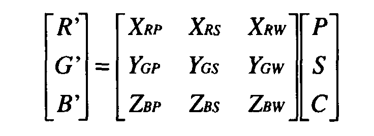
- a method of correcting color image data for a pixel comprising the steps of: providing image data for said pixel; converting said image data to a color space having a primary (P), secondary (S), and combined (C) color component; selecting a set of coefficients describing the contribution of the primary, secondary, and combined components to the output primaries, and calculating a corrected output value for each said output primary according to the following equation: where:
- the disclosed methods and systems provide independent control over the primary and secondary image colors, as well as over the combined color component-typically the white level. As implemented, the described methods and systems require very little additional processing power and therefore can be implemented in real time without excessive cost.
- the spectrum and maximum intensity of the primary color sources determine several key characteristics of a display system such as the white point and the purity of the secondary colors.
- a system designer may select a green color filter with a relatively broad pass band in order to provide a very high number of lumens to the projected image-especially when coupled with a light source that outputs a high proportion of its energy in the green spectrum band.
- the disproportionate amount of green light contributed to the white light output results in the white light having a greenish tinge. While the excess green contributed to the white light may not be objectionable, the high green level will result in a secondary colors such as yellow and cyan having too much green. What is needed is an efficient way to individually adjust the purity of not only the primary colors, but also the secondary colors and the white point.
- a method and apparatus has been developed that enables individual control of multiple color properties in a primary color display system.
- the method and apparatus disclosed herein allow the system designer great flexibility in the selection of primary color sources, while providing a means to compensate for the undesirable side effects of the combination of primary color sources.
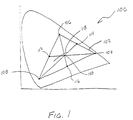
- Figure 1 is a CIE 1931 xy chromaticity diagram 100 of a first display system.
- the color space 102 of the display system is determined by the location of the system's red point 104, blue point 108, green point 106, and the relative intensity of the light provided at each of these primary color points. If each primary color provides the same intensity contribution to the white light level, then the secondary color points will be located midway between the primary color points, and the white point 110 will be located at the intersection of the lines connecting the primary and secondary colors as shown in Figure 1.
- the cyan point 112, yellow point 114, and magenta point 116 are all located midway between the primary color points.
- the white point 110 shown in Figure 1 is slightly to the magenta side of a reference white line 118.
- Figure 2 is a chromaticity diagram 200 of a second display system.
- the second display system has the same red, green, and blue points as the display system represented in Figure 1, but because the primary colors do not have equal intensities the secondary color points, as well as the white point, are shifted.
- the red light source provides less intensity than the blue light source, and much less than the green light source, resulting in a white point 210 that is shifted toward cyan.
- the yellow point 214 is shifted toward the green point 106, and the magenta point 216 is shifted toward the blue point 108.
- the display system represented by Figure 2 provides a lot of illumination to a white point that is suitably close to the reference white line 118, when the display system attempts to display a non-primary color represented by linear RGB data, the color will have a greenish or bluish tint.
- One means of compensating for the undesirable side effects of a given set of primary color sources is to provide secondary color and white information as well as the primary color information, and to use this additional information to generate a set of output primary data that compensates for the undesirable side effects.
- the secondary color and white intensity information is used to alter the amount each primary color source contributes to the secondary colors and white.
- this method transforms a three primary color system into a seven primary color system (RGBCMYW) including the three primary colors (RGB), the three secondary colors (CMY), and white (W) by remapping the color space to provide additional control over the secondary colors and white.
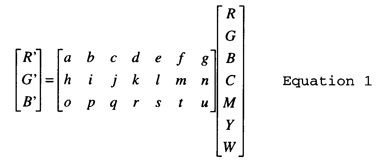
- the remapping system can be written as:
- Equation 1 Analysis of Equation 1 reveals that the coefficients represent three groups of signals: primary color (P) coefficients, represented by a , b , c , h , i , j , o , p , and q ; secondary color (S) coefficients, represented by d , e , f , k , l , m , r , s , and t ; and white (W) coefficients, represented by g , n , and u .
- P primary color
- S secondary color
- W white
- each primary and secondary color, as well as white can be controlled independently. For example, by setting the coefficient in location " m " to a value less than 1, the amount of green contributing to a yellow color is reduced, without affecting the contribution of green to white, pure green, or cyan.
- Each color, including the primary colors, can be manipulated in a similar manner-coefficient " p " allows blue to be added to green.
- Equation 1 provides a powerful tool for the independent control of each of the seven colors (RGBCYMW).
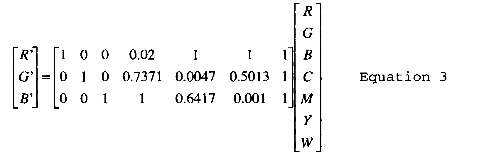
- Figure 3 is a chromaticity diagram 300 for the display system represented in Figure 2 after the secondary colors have been altered as described above. Equation 3 shows the matrix used to manipulate the system represented by Figure 3. As shown in Figure 3, the yellow point 314 and magenta point 316 have been moved toward the red point 104, while the cyan point 312 has been moved toward the blue point 108.
- Equations 1-3 provide a very valuable tool for adjusting the color response of a display system.
- the implementation of Equations 1-3 in a high resolution display system requires up to 21 multiplication operations, each using 14 bit inputs, 10 to 14 bit coefficients, and providing 14 bit outputs.
- the image data easily may be processed as described in Equations 1-3 and stored for later display. Performing the computations in real time, however, requires more processing power than is economically feasible to include in many display systems at this time. Therefore, there is a great need to simplify the calculations in order to enable the inclusion of the color space control features in display systems that do not have sufficient processing power to implement Equations 1-3.
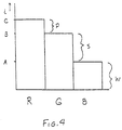
- Figure 4 is a graph of an example of three primary color intensity data values for a single pixel.
- the minimum of the three primary color values is the blue intensity value-which has an intensity of "A.” Since all three of the primary colors have an intensity of "A" or greater, the quantity "A" represents the white (W) component of the pixel. Therefore, the minimum primary color value, in this case blue, contributes only to the white component of the pixel.
- the two remaining primary colors are seen to contribute to one of the secondary colors.
- the two remaining primary colors red and green, form yellow.
- the intensity of the yellow component (Y) is equal to the minimum of the two remaining primary color intensity words after the subtraction of the white value from both words.
- the secondary color value is equal to S, the result of B - A. Therefore, the median primary color value, in this case green, contributes to both the white component and the yellow component of the pixel.
- P primary-secondary-white
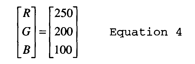
- the pixel represented in Figure 4 has a red component, a yellow component, and a white component.
- the input R value was 250
- the input G value was 200
- the input B value was 100
- the pixel is represented by all of the following matrices:
- Equation 8 any combination of the seven primary color input values (RGBCMYW) can be expressed using only three values, a primary color, a secondary color, and a white level, in PSW color space.
- the resulting PSW matrix is shown in Equation 8.
- Equation 8 The difficulty of implementing Equation 8 is the determination of the values for the coefficients X RP , X RS , Y GP , Y GS , Z BP , and Z BS .
- Review of Equation 2 shows that the first three columns of the coefficient matrix are used to control the primary colors, the second group of three columns of the coefficient matrix are used to control the secondary color, and the last column controls the white color.
- the coefficients for Equation 8 may be taken directly from the coefficients of Equation 1-all that is required is to select the columns based on the identity of the primary and secondary colors of Equation 8, which is determined by the relative strengths of the red, green, and blue inputs.
- the first column of these values, X RP , X RS , and Y GP is the column of coefficients for the corresponding primary color from Equation 1.
- the second column of these values, Y GS , Z BP , and Z BS correspond to the coefficients for the corresponding secondary color from Equation 1.
- the first column of the coefficient matrix is used for the first column, X RP , X RS , and Y GP , of Equation 8.
- the second column is used when the green intensity value is the maximum
- the third column is used when the blue intensity value is the maximum.
- the proper secondary color is cyan and the fourth column of the coefficient matrix of Equation 1 is used as the second column, Y GS , Z BP , and Z BS , of Equation 8.
- the secondary color is magenta and the fifth column of the coefficient matrix is used, and when the blue intensity value is the minimum, the secondary color is yellow and the sixth column of the coefficient matrix is used.
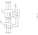
- FIG. 5 is a block diagram depicting one embodiment of the improved color correction.
- RGB data for a given pixel is input into the RGB to PSW converter 502.
- the RGB to PSW converter 502 compares the three intensity values and outputs the greatest on signal P, the median on signal S, and the minimum on signal W. P, S, and W are then driven to one set of inputs in the 3 x 3 multiplier 504.
- the RGB to PSW converter 502 also drives two signals to a coefficient selection block 506.
- the coefficient selection block 506 provides the coefficients used by the 3 x 3 multiplier 504.
- the output of the 3 x 3 multiplier 504 is the processed RGB data of Equation 8.
- Figure 6 is a schematic diagram of one possible circuit for implementing the methods described herein.
- the circuit of Figure 6 implements either Equation 9 or Equation 10, depending on the polarity of the mode select signal (P7_Mode). When Equation 9 is implemented, the enhanced color correction is not implemented.
- Several delay blocks 604 are used to synchronize the circuit of Figure 6.
- the adders 608 and multipliers 606 are also clocked.
- blocks 610 perform a clocked subtraction of various combinations of the delayed RGB data. The sign bit from the result of each subtraction is used by the combinatorial logic block 612 to determine which of the RGB inputs had the maximum, median, and minimum value.
- the output of the combinatorial logic block 612 is used to gate the proper RGB value, the minimum of the three RGB values, through the clocked white multiplexer 614, after which the white value is delayed one clock before being input to the multipliers 606.
- Other outputs of the combinatorial logic block 612 gate the proper input, the difference between the median and minimum RGB values, through the secondary color multiplexer 618, and the difference between the maximum and median RGB values through the primary color multiplexer 616.
- the outputs of the primary and secondary color multiplexers 616, 618 are passed through conditional 2's complement inverters 620 before being input to a set of multipliers 606.
- the conditional 2's complement inverters 620 invert their input signals when the inputs are negative-in effect providing the absolute value of the subtraction operation.
- green data is passed through the white channel multiplexer 614, red data is passed through the primary channel multiplexer 616, and blue data is passed through the secondary channel multiplexer 618.
- the outputs of the multiplexers 614, 616, and 618, are delayed by the conditional 2's complement inverters 620 or a delay block 604 before being input to the multipliers.
- the second input to each multiplier 606 is selected from a set of coefficients stored in a memory 622 associated with each multiplier 606.
- the memories 622 of Figure 6 show an interleaved set of memory locations. These locations are used to store a second set of coefficients that are accessed to facilitate testing of various coefficients.
- the test signal "Split" is used to select between the two versions of each coefficient. By toggling Split during a frame, various image pixels will use the "A" set of coefficients while the remainder of the pixels will use the "B" set of coefficients. Thus, the effects of various sets of coefficients can be compared directly.
- the offset 624 inputs to the adders 608 are also provided for testing purposes.
- the color correction can be implemented before or after a gamma correction operation, or implemented as part of the degamma scaling operation.
- other embodiments use logic thresholds to sample the YC R C B values to determine the proper primary and secondary colors and implement the color correction techniques in the Y'C R 'C B ' to R'G'B' conversion matrix.
- the color correction described herein is applicable to both additive and subtractive color systems.
- the term "combined primary” will be used to describe the mixture of all of the primary colors whether describing white in an additive system or black in a subtractive system.
- FIG. 7 is a block diagram of a film to video transfer system utilizing the improved color correction 702 of the present invention to translate digitized image data prior to storing the digitized data.
- the color corrected data is later retrieved and displayed by display system 704.
- FIG. 8 is a block diagram showing a display system 802 with the improved color correction 804 capability.
- the color correction 804 can be selected by a viewer, for example through the use of a remote control and on-screen programming, to enable the viewer to select from several color correction modes. The use of multiple color correction modes allows the user to optimize the color correction based on the selected image source.
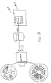
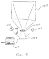
- FIG 9 is a schematic view of an image projection system 1000 incorporating the improved color correction of the present invention.
- light from light source 1004 is focused on a micromirror 1002 by lens 1006.
- lens 1006 is typically a group of lenses and mirrors which together focus and direct light from the light source 1004 onto the surface of the micromirror device 1002.
- Controller 1014 receives image intensity data and control signals and processes them according to the teachings herein to obtain color corrected image intensity data signals.
- the color corrected image intensity data signals are then transferred from controller 1014 to the micromirror device 1002.
- the color corrected image intensity data causes some mirrors to rotate to an on position and others to rotate to an off position.
- Mirrors rotated to an off position reflect light to a light trap 1008 while mirrors rotated to an on position reflect light to projection lens 1010, which is shown as a single lens for simplicity.
- Projection lens 1010 focuses the light modulated by the micromirror device 1002 onto an image plane or screen 1012.
Landscapes
- Engineering & Computer Science (AREA)
- Multimedia (AREA)
- Signal Processing (AREA)
- Image Processing (AREA)
- Facsimile Image Signal Circuits (AREA)
- Color Image Communication Systems (AREA)
- Processing Of Color Television Signals (AREA)
Abstract
Description



Claims (12)
- A method of correcting color image data for a pixel, the method comprising:providing intensity data for three primary colors, plurality of secondary colors, and a combined color for said pixel;providing a set of matrix coefficients for each output primary color, one said coefficient for describing the contribution said output primary color makes to each of the primary, secondary, and combined colors; andsumming the products of said matrix coefficients and corresponding said intensity data to provide a corrected intensity data value for each output primary.
- The method of Claim 1, further comprising the step of:storing said corrected intensity data values.
- The method of Claim 1 or Claim 2, further comprising the step of:forming an image pixel using said corrected intensity data values.
- The method of any of Claims 1 to 3, further comprising the step of:printing an image pixel using said corrected intensity data values.
- A method of correcting color image data for a pixel, the method comprising:providing image data for said pixel, said image data comprising a maximum input intensity value, a median input intensity value, and a minimum input intensity value, each said input intensity value corresponding to one of three primary colors;converting said image data to a color space having a primary, secondary, and combined color component, said combined color component equal to said minimum input intensity value, said primary color component equal to the difference between said maximum input intensity value and said minimum input intensity value, and said secondary color component equal to the difference between said maximum input intensity value and said median input intensity value;providing coefficients describing the contribution made each of three output primary colors to the formation of said primary, secondary, and combined color components, said coefficients dependent on which of said three primary colors corresponds to said maximum, median, and minimum input intensity values;summing the products of said coefficients and said primary, secondary, and combined color components to provide a corrected intensity data value for each output primary.
- The method of Claim 5, further comprising the step of:storing said corrected intensity data values.
- The method of Claim 5 or Claim 6, further comprising the step of:forming an image pixel using said corrected intensity data values.
- The method of any of Claims 5 to 7, wherein said step of providing coefficients further comprises the step of:providing coefficients describing the contribution made each of three output primary colors to the formation of said primary, secondary, and combined color components, said coefficients dependent on which of said three primary colors corresponds to said maximum, median, and minimum input intensity values and operable to compensate for a gamma correction applied to said image data.
- A method of correcting color image data for a pixel, the method comprising:providing image data for said pixel, said image data comprising a maximum input intensity value, and median input intensity value, and a minimum input intensity value, each said input intensity value corresponding to one of three primary colors;converting said image data to a color space having a primary (P), secondary (S), and combined (C) color component, said combined color component equal to said minimum input intensity value, said primary color component equal to the difference between said maximum input intensity value and said minimum input intensity value, and said secondary color component equal to the difference between said maximum input intensity value and said median input intensity value;providing a dynamic coefficient (XRP) describing the contribution of said primary color component to a first output primary (R');providing a dynamic coefficient (XRS) describing the contribution of said secondary color component to said first output primary (R');providing a dynamic coefficient (XRC) describing the contribution of said combined color component to said first output primary (R');providing a dynamic coefficient (YGP) describing the contribution of said primary color component to a second output primary (G');providing a dynamic coefficient (YGS) describing the contribution of said secondary color component to said second output primary (G');providing a dynamic coefficient (YGC) describing the contribution of said combined color component to said second output primary (G');providing a dynamic coefficient (ZBP) describing the contribution of said primary color component to a third output primary (B');providing a dynamic coefficient (ZBS) describing the contribution of said secondary color component to said third output primary (B');providing a dynamic coefficient (ZBC) describing the contribution of said combined color component to said third output primary (B');calculating a corrected output value for each said output primary according to the following equation:

- The method of Claim 9, further comprising the step of:storing said corrected intensity data values.
- The method of Claim 9 or Claim 10, further comprising the step of:forming an image pixel using said corrected intensity data values.
- The method of any of Claims 9 to 11, said steps of providing a dynamic coefficient further comprising the step of:providing a dynamic coefficient compensating for a gamma correction applied to said image data.
Applications Claiming Priority (2)
| Application Number | Priority Date | Filing Date | Title |
|---|---|---|---|
| US13173399P | 1999-04-30 | 1999-04-30 | |
| US131733P | 1999-04-30 |
Publications (2)
| Publication Number | Publication Date |
|---|---|
| EP1063840A2 true EP1063840A2 (en) | 2000-12-27 |
| EP1063840A3 EP1063840A3 (en) | 2004-07-21 |
Family
ID=22450775
Family Applications (1)
| Application Number | Title | Priority Date | Filing Date |
|---|---|---|---|
| EP00201568A Withdrawn EP1063840A3 (en) | 1999-04-30 | 2000-05-02 | Enchanced color correction |
Country Status (5)
| Country | Link |
|---|---|
| US (1) | US6594387B1 (en) |
| EP (1) | EP1063840A3 (en) |
| JP (1) | JP2000358252A (en) |
| KR (1) | KR100703105B1 (en) |
| TW (1) | TW476217B (en) |
Cited By (4)
| Publication number | Priority date | Publication date | Assignee | Title |
|---|---|---|---|---|
| WO2002007431A2 (en) | 2000-07-17 | 2002-01-24 | Matsushita Electric Industrial Co., Ltd. | Multidisplay apparatus and chromaticity adjustment method for in the multidisplay apparatus |
| EP1227687A3 (en) * | 2000-12-30 | 2005-05-25 | Texas Instruments Incorporated | System for reducing color separation artifacts in sequential color displays |
| US6961066B2 (en) | 1999-04-13 | 2005-11-01 | Athentech Technologies, Inc. | Automatic color adjustment for digital images |
| WO2010052716A3 (en) * | 2008-11-05 | 2010-07-01 | Shachar Carmi | Apparatus and method for chroma-key processing |
Families Citing this family (44)
| Publication number | Priority date | Publication date | Assignee | Title |
|---|---|---|---|---|
| JP3707350B2 (en) * | 2000-05-08 | 2005-10-19 | セイコーエプソン株式会社 | Image display system, projector, image processing method, and information storage medium |
| US6870523B1 (en) * | 2000-06-07 | 2005-03-22 | Genoa Color Technologies | Device, system and method for electronic true color display |
| JP4489262B2 (en) * | 2000-07-28 | 2010-06-23 | 日立プラズマディスプレイ株式会社 | Color reproduction correction circuit for color display and color display |
| CA2420195A1 (en) * | 2000-08-18 | 2002-02-28 | Paul Reed Smith Guitars, Limited Partnership (Maryland) | Method of color accentuation |
| WO2005020130A2 (en) * | 2000-08-18 | 2005-03-03 | Paul Reed Smith Guitars, Limited Partnership | Method of color accentuation with compensation and adjustment |
| US6950109B2 (en) * | 2000-10-23 | 2005-09-27 | Sun Microsystems, Inc. | Multi-spectral color correction |
| US7119925B2 (en) * | 2000-11-10 | 2006-10-10 | Seiko Epson Corporation | Image processing, image reading apparatus and image processing method |
| US7352488B2 (en) * | 2000-12-18 | 2008-04-01 | Genoa Color Technologies Ltd | Spectrally matched print proofer |
| US6757429B2 (en) * | 2001-02-21 | 2004-06-29 | Boly Media Communications Inc. | Method of compressing digital images |
| US8289266B2 (en) | 2001-06-11 | 2012-10-16 | Genoa Color Technologies Ltd. | Method, device and system for multi-color sequential LCD panel |
| EP1419497A4 (en) * | 2001-06-11 | 2005-11-16 | Genoa Color Technologies Ltd | DEVICE, SYSTEM AND METHOD FOR COLOR DISPLAY |
| US7714824B2 (en) * | 2001-06-11 | 2010-05-11 | Genoa Color Technologies Ltd. | Multi-primary display with spectrally adapted back-illumination |
| EP1461665A4 (en) * | 2002-01-07 | 2006-11-02 | Genoa Color Technologies Ltd | ELECTRONIC COLOR DISPLAY USED FOR THE PRODUCTION OF A SCREEN TEST |
| CN101840687B (en) * | 2002-04-11 | 2013-09-18 | 格诺色彩技术有限公司 | Color display device with enhanced attributes and method thereof |
| WO2004004328A1 (en) * | 2002-06-26 | 2004-01-08 | Matsushita Electric Industrial Co., Ltd. | Characteristic correcting device |
| CN1717715A (en) * | 2002-07-24 | 2006-01-04 | 吉诺彩色技术有限公司 | High brightness wide gamut display |
| US20050213125A1 (en) * | 2002-08-19 | 2005-09-29 | Paul Reed Smith Guitars, Limited Partnership | Method of color accentuation with compensation and adjustment |
| CN1742304A (en) | 2003-01-28 | 2006-03-01 | 皇家飞利浦电子股份有限公司 | Optimal subpixel arrangement for displays with more than three primary colors |
| EP1591994A1 (en) * | 2003-02-07 | 2005-11-02 | Sanyo Electric Co., Ltd. | Color space correction circuit in display device |
| EP1660937A2 (en) * | 2003-08-04 | 2006-05-31 | Genoa Color Technologies Ltd. | Multi-primary color display |
| CN1910901B (en) * | 2003-11-04 | 2013-11-20 | 皇家飞利浦电子股份有限公司 | Smart clipper for mobile displays |
| US6885380B1 (en) * | 2003-11-07 | 2005-04-26 | Eastman Kodak Company | Method for transforming three colors input signals to four or more output signals for a color display |
| US7969448B2 (en) | 2003-11-20 | 2011-06-28 | Samsung Electronics Co., Ltd. | Apparatus and method of converting image signal for six color display device, and six color display device having optimum subpixel arrangement |
| US7495722B2 (en) * | 2003-12-15 | 2009-02-24 | Genoa Color Technologies Ltd. | Multi-color liquid crystal display |
| EP2423911A3 (en) * | 2003-12-15 | 2012-04-04 | Genoa Color Technologies Ltd. | Multi-primary liquid crystal display |
| US7165847B2 (en) * | 2003-12-23 | 2007-01-23 | Texas Instruments Incorporated | Method and system for light processing using a gold segment |
| US7181065B2 (en) * | 2004-01-07 | 2007-02-20 | Texas Instruments Incorporated | Enhanced color correction circuitry capable of employing negative RGB values |
| JP4549881B2 (en) | 2004-03-18 | 2010-09-22 | シャープ株式会社 | Color signal conversion apparatus, display unit, color signal conversion program, and computer-readable recording medium recording the color signal conversion program |
| JP5268996B2 (en) * | 2004-03-18 | 2013-08-21 | シャープ株式会社 | Color display device and color display method |
| US20060221019A1 (en) | 2005-03-29 | 2006-10-05 | Texas Instruments Incorporated | Spatial light modulation display system |
| US7265794B2 (en) * | 2005-09-01 | 2007-09-04 | Texas Instruments Incorporated | Managing the color temperature for a light source array |
| US20070081102A1 (en) * | 2005-10-11 | 2007-04-12 | Texas Instruments Incorporated | Apparatus and method for automatically adjusting white point during video display |
| US8587621B2 (en) | 2005-11-28 | 2013-11-19 | Genoa Color Technologies Ltd. | Sub-pixel rendering of a multiprimary image |
| US7737989B2 (en) * | 2006-10-27 | 2010-06-15 | Texas Instruments Incorporated | System and method for computing color correction coefficients |
| US8063911B2 (en) | 2007-11-30 | 2011-11-22 | Texas Instruments Incorporated | System and method for gamut mapping of out-of-gamut signals |
| US8411206B2 (en) * | 2007-12-27 | 2013-04-02 | Texas Instruments Incorporated | Apparatus and method for decoding extended color space data |
| US8624907B2 (en) * | 2009-06-26 | 2014-01-07 | Intel Corporation | Graphics analysis techniques |
| US20100332987A1 (en) * | 2009-06-26 | 2010-12-30 | Cormack Christopher J | Graphics analysis techniques |
| US8581916B2 (en) * | 2009-06-26 | 2013-11-12 | Intel Corporation | Graphics analysis techniques |
| TWI409794B (en) * | 2009-11-26 | 2013-09-21 | Chunghwa Picture Tubes Ltd | Color calibrator of display apparatus |
| US10402661B2 (en) | 2013-07-22 | 2019-09-03 | Opengate Development, Llc | Shape/object recognition using still/scan/moving image optical digital media processing |
| JP7235540B2 (en) * | 2019-03-07 | 2023-03-08 | ソニー・オリンパスメディカルソリューションズ株式会社 | Medical image processing device and medical observation system |
| KR20250099042A (en) | 2023-12-22 | 2025-07-01 | 울산과학기술원 | Digital holographic device and control method thereof |
| CN120766615A (en) * | 2025-08-27 | 2025-10-10 | 西安诺瓦星云科技股份有限公司 | Correction method, terminal device, display system and readable storage medium |
Family Cites Families (15)
| Publication number | Priority date | Publication date | Assignee | Title |
|---|---|---|---|---|
| US3558806A (en) * | 1968-04-01 | 1971-01-26 | Rca Corp | Matrixing apparatus |
| JPS56123540A (en) * | 1980-03-04 | 1981-09-28 | Dainippon Printing Co Ltd | Color reproducing method in print color simulator |
| JPS58219867A (en) * | 1982-06-14 | 1983-12-21 | Canon Inc | Color reproduction method |
| US4670780A (en) * | 1985-05-28 | 1987-06-02 | Tektronix, Inc. | Method of matching hardcopy colors to video display colors in which unreachable video display colors are converted into reachable hardcopy colors in a mixture-single-white (MSW) color space |
| CA2055058C (en) * | 1990-12-31 | 1996-08-06 | Anthony Joseph Dattilo | Automatic correction for color printing |
| DE4310727C2 (en) * | 1992-04-06 | 1996-07-11 | Hell Ag Linotype | Method and device for analyzing image templates |
| US5657137A (en) * | 1992-05-04 | 1997-08-12 | Hewlett-Packard Company | Color digital halftoning using black and secondary color replacement |
| US5377024A (en) * | 1992-05-04 | 1994-12-27 | Hewlett-Packard | Apparatus for forming color images using a hue-plus-gray color model |
| JP3086535B2 (en) * | 1992-06-05 | 2000-09-11 | 富士写真フイルム株式会社 | Image processing method and apparatus |
| US5512961A (en) * | 1993-03-24 | 1996-04-30 | Apple Computer, Inc. | Method and system of achieving accurate white point setting of a CRT display |
| JP3128429B2 (en) | 1993-08-27 | 2001-01-29 | 三菱電機株式会社 | Image processing method and apparatus |
| US5754448A (en) * | 1995-07-12 | 1998-05-19 | Minnesota Mining And Manufacturing Company | System and method for color characterization and transformation |
| GB9614488D0 (en) * | 1996-07-10 | 1996-09-04 | Crosfield Electronics Ltd | Colour correction |
| JPH10322710A (en) * | 1997-05-15 | 1998-12-04 | Casio Comput Co Ltd | Color imaging apparatus and color image correction method |
| US6453067B1 (en) * | 1997-10-20 | 2002-09-17 | Texas Instruments Incorporated | Brightness gain using white segment with hue and gain correction |
-
2000
- 2000-04-28 US US09/561,160 patent/US6594387B1/en not_active Expired - Lifetime
- 2000-04-29 KR KR1020000023081A patent/KR100703105B1/en not_active Expired - Fee Related
- 2000-05-01 JP JP2000132429A patent/JP2000358252A/en active Pending
- 2000-05-02 EP EP00201568A patent/EP1063840A3/en not_active Withdrawn
- 2000-05-05 TW TW089108064A patent/TW476217B/en not_active IP Right Cessation
Cited By (5)
| Publication number | Priority date | Publication date | Assignee | Title |
|---|---|---|---|---|
| US6961066B2 (en) | 1999-04-13 | 2005-11-01 | Athentech Technologies, Inc. | Automatic color adjustment for digital images |
| WO2002007431A2 (en) | 2000-07-17 | 2002-01-24 | Matsushita Electric Industrial Co., Ltd. | Multidisplay apparatus and chromaticity adjustment method for in the multidisplay apparatus |
| EP1227687A3 (en) * | 2000-12-30 | 2005-05-25 | Texas Instruments Incorporated | System for reducing color separation artifacts in sequential color displays |
| WO2010052716A3 (en) * | 2008-11-05 | 2010-07-01 | Shachar Carmi | Apparatus and method for chroma-key processing |
| US8611699B2 (en) | 2008-11-05 | 2013-12-17 | Shachar Carmi | Apparatus and method for chroma-key processing |
Also Published As
| Publication number | Publication date |
|---|---|
| TW476217B (en) | 2002-02-11 |
| US6594387B1 (en) | 2003-07-15 |
| JP2000358252A (en) | 2000-12-26 |
| KR100703105B1 (en) | 2007-04-05 |
| KR20010029676A (en) | 2001-04-06 |
| EP1063840A3 (en) | 2004-07-21 |
Similar Documents
| Publication | Publication Date | Title |
|---|---|---|
| US6594387B1 (en) | Enhanced color correction | |
| US8115787B2 (en) | Device, system and method of data conversion for wide gamut displays | |
| US6453067B1 (en) | Brightness gain using white segment with hue and gain correction | |
| EP1237379B1 (en) | Image processing for digital cinema | |
| EP1239668B1 (en) | System for optimizing the display and rendering of digital images for digital mastering | |
| JP6362595B2 (en) | A display system that reduces metamerism mismatch between observers | |
| US7336822B2 (en) | Enhanced color correction circuitry capable of employing negative RGB values | |
| JP3290190B2 (en) | Image recording device | |
| US20090060326A1 (en) | Image processing apparatus and method | |
| EP1370072A2 (en) | Color conversion device and color conversion method | |
| US6774953B2 (en) | Method and apparatus for color warping | |
| JP7796647B2 (en) | Color gamut projection system and method | |
| US6985253B2 (en) | Processing film images for digital cinema | |
| JPH07271973A (en) | Color image processor | |
| US20030214520A1 (en) | Real-time gradation control | |
| WO2002099776A2 (en) | Device, system and method for displaying graphics in mixed formats on a monitor | |
| JP2527165B2 (en) | Image processing method and apparatus | |
| Imai et al. | Design of a framework for HDR sequence rendering evaluation | |
| JP2021002720A (en) | Image conversion method, image processing device, and image display device | |
| IL159233A (en) | Device, system and method of data conversion for wide gamut displays |
Legal Events
| Date | Code | Title | Description |
|---|---|---|---|
| PUAI | Public reference made under article 153(3) epc to a published international application that has entered the european phase |
Free format text: ORIGINAL CODE: 0009012 |
|
| AK | Designated contracting states |
Kind code of ref document: A2 Designated state(s): AT BE CH CY DE DK ES FI FR GB GR IE IT LI LU MC NL PT SE |
|
| AX | Request for extension of the european patent |
Free format text: AL;LT;LV;MK;RO;SI |
|
| RIC1 | Information provided on ipc code assigned before grant |
Ipc: 7H 04N 9/67 A |
|
| PUAL | Search report despatched |
Free format text: ORIGINAL CODE: 0009013 |
|
| RIC1 | Information provided on ipc code assigned before grant |
Ipc: 7H 04N 9/68 B Ipc: 7H 04N 1/60 B Ipc: 7H 04N 9/67 A |
|
| AK | Designated contracting states |
Kind code of ref document: A3 Designated state(s): AT BE CH CY DE DK ES FI FR GB GR IE IT LI LU MC NL PT SE |
|
| AX | Request for extension of the european patent |
Extension state: AL LT LV MK RO SI |
|
| 17P | Request for examination filed |
Effective date: 20050121 |
|
| AKX | Designation fees paid |
Designated state(s): AT BE CH CY DE DK ES FI FR GB GR IE IT LI LU MC NL PT SE |
|
| 18D | Application deemed to be withdrawn |
Effective date: 20080226 |
|
| D18D | Application deemed to be withdrawn (deleted) | ||
| STAA | Information on the status of an ep patent application or granted ep patent |
Free format text: STATUS: THE APPLICATION HAS BEEN WITHDRAWN |
|
| 18W | Application withdrawn |
Effective date: 20110818 |