EP1063794A2 - Optical transmitter and wavelength multiplexing optical transmission apparatus using the same - Google Patents
Optical transmitter and wavelength multiplexing optical transmission apparatus using the same Download PDFInfo
- Publication number
- EP1063794A2 EP1063794A2 EP00113367A EP00113367A EP1063794A2 EP 1063794 A2 EP1063794 A2 EP 1063794A2 EP 00113367 A EP00113367 A EP 00113367A EP 00113367 A EP00113367 A EP 00113367A EP 1063794 A2 EP1063794 A2 EP 1063794A2
- Authority
- EP
- European Patent Office
- Prior art keywords
- light
- wavelength
- optical
- semiconductor laser
- laser diode
- Prior art date
- Legal status (The legal status is an assumption and is not a legal conclusion. Google has not performed a legal analysis and makes no representation as to the accuracy of the status listed.)
- Withdrawn
Links
Images


Classifications
-
- H—ELECTRICITY
- H04—ELECTRIC COMMUNICATION TECHNIQUE
- H04B—TRANSMISSION
- H04B10/00—Transmission systems employing electromagnetic waves other than radio-waves, e.g. infrared, visible or ultraviolet light, or employing corpuscular radiation, e.g. quantum communication
- H04B10/50—Transmitters
- H04B10/572—Wavelength control
-
- H—ELECTRICITY
- H04—ELECTRIC COMMUNICATION TECHNIQUE
- H04B—TRANSMISSION
- H04B10/00—Transmission systems employing electromagnetic waves other than radio-waves, e.g. infrared, visible or ultraviolet light, or employing corpuscular radiation, e.g. quantum communication
- H04B10/50—Transmitters
- H04B10/501—Structural aspects
- H04B10/506—Multiwavelength transmitters
-
- H—ELECTRICITY
- H04—ELECTRIC COMMUNICATION TECHNIQUE
- H04B—TRANSMISSION
- H04B10/00—Transmission systems employing electromagnetic waves other than radio-waves, e.g. infrared, visible or ultraviolet light, or employing corpuscular radiation, e.g. quantum communication
- H04B10/50—Transmitters
- H04B10/564—Power control
Definitions
- the present invention generally relates to an optical transmitter using a semiconductor laser diode as a light source. More specifically, the present invention is directed to both an optical transmitter having a function capable of monitoring an oscillation wavelength of a semiconductor laser diode so as to control the monitored oscillation wavelength to obtain a predetermined wavelength, and a wavelength multiplexing optical transmission apparatus.
- the following is important in a wavelength multiplexing optical transmission. That is, while an oscillation wavelength of a semiconductor laser diode is monitored, the oscillation wavelength is controlled so as to be stabilized.
- a means for stabilizing an oscillation wavelength of a semiconductor laser diode for instance, one method is known by which a temperature thereof is kept constant so as to maintain the oscillation wavelength of the semiconductor laser diode at a constant wavelength.
- this conventional method can hardly suppress this wavelength variation.
- the wavelengths in a wavelength multiplexing optical communication with high density, while an interval among oscillation wavelengths of semiconductor laser diodes is narrowed, the wavelengths must be set with high precision. However, the wavelength control operation by the conventional method cannot satisfactorily set the wavelengths with high precision.
- a control method capable of controlling an oscillation wavelength of a semiconductor laser diode in order not to produce a change in this oscillation wavelength backward projection light of the semiconductor laser diode is detected by a photodetector, and a control operation is carried out based upon the detected backward projection light in such a way that a laser light output from the semiconductor laser diode can be made constant.
- a temperature of a semiconductor laser diode is controlled to be kept constant.
- Japanese Patent Application Laid-open No. Hei 9-219554 discloses such a control arrangement that two optical filters whose transmission characteristics own the gradients opposite to each other are employed so as to adjust the temperature of the semiconductor laser diode, thereby controlling the oscillation wavelength of this semiconductor laser diode.
- the backward projection light of the semiconductor laser diode is subdivided into two beams of projection light, transmission light and reflection light, by the beam splitter arranged at the post stage of this semiconductor laser diode.
- Both the transmission light and the reflection light are filtered by the wavelength filters having the transmission characteristics opposite to each other, and then the filtered transmission light and the filtered reflection light are detected by the light receiving devices.
- both the light output (optical output) of the semiconductor laser diode and the oscillation wavelength thereof are controlled.
- the oscillation wavelength is controlled by changing the temperature of the semiconductor laser diode in such a manner that the shift in the oscillation wavelength is corrected based upon the output difference between the light levels detected by the respective light receiving devices.
- the oscillation wavelength of the semiconductor laser diode may, if not satisfiable, be stabilized irrespective of the aging effect of this semiconductor laser diode.
- the beam splitter since the beam splitter is employed, the light is newly polarized. Also, the beam splitting ratio of the beam splitter itself is readily varied due to the temperature change, so that it is practically difficult to obtain such a beam splitter element capable of splitting a light beam, while keeping an ideal predetermined ratio and a stable condition. Furthermore, it is practically difficult to realize wavelength filters whose transmission characteristics owns gradients opposite to each other.
- Japanese Patent Application Laid-open No. Hei 10-209546 discloses the control arrangement in which the forward projection light of the semiconductor laser diode is separated by the photocoupler without using such beam splitter, and the transmission light and the reflection light are detected by the photodetectors, respectively, by way of the interference filters. Then, the oscillation wavelength of the semiconductor laser diode is controlled based upon the difference in the light level detection amounts.
- An object of the present invention is to provide an optical transmitter and a wavelength multiplexing optical transmission apparatus using this optical transmitter, capable of controlling an oscillation wavelength of a semiconductor laser diode so as to stabilize the oscillation wavelength, while neither forward projection light, nor a beam splitter is employed.
- an optical transmitter comprising: a semiconductor laser diode; an optical waveguide path into which forward projection light of this semiconductor laser diode is entered; a wavelength filter; and two light receiving devices, i.e, first and second light receiving devices.
- the wavelength filter owns a function of containing an oscillation wavelength of the semiconductor laser diode in a wavelength band where a transmission wavelength band is transferred to a reflection wavelength band and vice versa, of causing a portion of backward projection light of the semiconductor laser diode to pass therethrough to output transmission light, and also of reflecting the remaining light of the backward projection light to output reflection light.
- the first light receiving device detects a light level of the transmission light to output a transmission light level
- the second light receiving device detects a light level of the reflection light to output a reflection light level.
- the optical transmitter further comprises a wavelength control circuit, and is characterized in that this wavelength control circuit controls an oscillation wavelength of the semiconductor laser diode based upon both the transmission light level and the reflection light level.
- this wavelength control circuit controls an oscillation wavelength of the semiconductor laser diode based upon both the transmission light level and the reflection light level.
- a wavelength filter having the following wavelength characteristic is selected. That is, when projection light which passes through the wavelength filter and projection light which is reflected by the wavelength filter are outputted at the same ratios, the oscillation wavelength becomes " ⁇ L".
- the wavelength filter owns a wavelength characteristic containing an oscillation wavelength of the semiconductor laser diode in a wavelength band where a transmission wavelength band is transferred to a reflection wavelength band and vice versa.
- the oscillation wavelength is shifted, the ratio of the transmission light of the wavelength filter to the reflection light thereof is changed.
- the oscillation wavelength of the semiconductor laser diode is shifted from the target wavelength of " ⁇ 0"
- the light level of the transmission light (will be referred to as a "transmission light level” hereinafter) is increased in accordance with the shifted wavelength component.
- the light level of the reflection light (will be referred to as a “reflection light level” hereinafter) is decreased.
- the shift in the wavelengths can be predicted based on the relationship between the transmission light level and the reflection light level, and then the wavelength can be controlled in such a manner that the oscillation wavelength is shifted along the reverse direction in connection with this wavelength variation amount.
- the wavelength characteristic of the wavelength filter may be preferably set as follows: That is, when the oscillation wavelength of the semiconductor laser diode is equal to a desired wavelength, the light amount of the laser light reflected by the wavelength filter is substantially equal to the light amount of the laser light passing through this wavelength filter. This is because the sensitivity with respect to the wavelength variation is increased.
- the present invention is not limited to this method, but may be applied to other methods for controlling the oscillation wavelength based upon the relationship between the transmission light level and the reflection light level.
- wavelength control method in which a ratio of both the transmission/reflection light levels is calculated, and this calculated ratio is controlled to be equal to a predetermined reference ratio
- wavelength control method in which a difference between the transmission/reflection light levels is calculated, and this calculated difference is controlled to be equal to a predetermined reference value.
- a semiconductor laser diode is arranged on a temperature control element such as a Peltier effect element, and a peripheral temperature of this semiconductor laser diode is changed.
- one of these projection light is not monitored, for example, the variation in the absolute value of the light level of the transmission light from the wavelength filter is not monitored. Instead, the ratio of the transmission light to the reflection light is monitored.
- a light level of a summation of transmission light and reflection light is also calculated, and a wavelength control operation is carried out in such a manner that this summation light level becomes constant.
- the output level of the semiconductor laser diode may also be stabilized at the same time.
- the output level of the semiconductor laser diode may be controlled by controlling, for instance, an injection current into an element.
- the following wavelength control method may be carried out. That is, a circuit controls the first temperature control element in such a manner that a difference between the transmission light level and the reflection light level is divided by the summation light level and then the calculated difference is ruled to obtain a ruled level difference, and the ruled level difference is used to control the wavelength of the semiconductor laser diode.
- the optical transmitter may be arranged by comprising: a second temperature control element for controlling a peripheral temperature of the wavelength filter; and a second temperature control circuit for controlling the second temperature control element in such a manner that the peripheral temperature of the wavelength filter becomes constant.
- the above-explained optical waveguide path may be made of such an optical waveguide path formed on a board, or an optical fiber.
- a lens may be arranged between the semiconductor laser diode and the wavelength filter, which converts the backward projection light into a collimated beam, so that a coupling efficiency of this backward projection light to the light receiving device may be increased.
- the wavelength multiplexing optical transmission apparatus is equipped with an optical transmission station; an optical reception station; and an optical transmission path for connecting the optical transmission station to the optical reception station, which optically transmits a plurality of signal light having wavelengths different from each other between the optical transmission station and the optical reception station.
- the above-explained optical transmission station corresponds to the optical transmitter of the present invention.
- the optical transmission station includes a plurality of optical transmitters of the present invention in which wavelengths of signal light outputted from the optical waveguide paths (optical fibers) are different from each other, and a wavelength division multiplexer for wavelength-multiplexing the signal light, and the optical reception station includes an optical receiver for receiving the respective signal light.
- Fig. 1 illustratively shows one structural example of the conventional optical transmitter.
- Fig. 1 is a diagram for indicating the arrangement of the conventional wavelength control apparatus for the semiconductor laser diode, disclosed in the above-explained publication.
- This wavelength control apparatus is arranged by that the backward projection light of the semiconductor laser diode 26 is split into two beams of the transmission light and the reflection light by the beam splitter 28 provided at the backward position of this semiconductor laser diode 26, and both the transmission light and the reflection light are filtered by the wavelength filters 29 and 30 whose transmission characteristics are opposite to each other, and then the filtered transmission light and the filtered reflection light are detected by the light receiving devices 31 and 32.
- the signals which are detected by the respective light receiving devices 31 and 32 and related to the light levels are processed by the control circuits 33 and 34. Both the light output and the oscillation wavelength of the semiconductor laser diode 26 by the LD drive circuit 35 and the temperature control circuit 37 are controlled based on the processed signals.
- the oscillation wavelength of the semiconductor laser diode is controlled by changing the temperature of this semiconductor laser diode in order that the shift of the oscillation wavelength is corrected based upon the power difference of the light levels detected by the respective light receiving devices 31 and 32.
- the oscillation wavelength of the semiconductor laser diode may be stabilized irrespective of the aging effect of this oscillation wavelength.
- Fig. 2 is a schematic diagram for showing an arrangement of an optical transmitter according to a first embodiment mode of the present invention.
- the optical transmitter of this first embodiment mode is mainly arranged by a semiconductor laser diode unit 1, a wavelength monitor unit 2, and a semiconductor laser diode control unit 3.
- the semiconductor laser diode unit 1 is provided with a semiconductor laser diode 4, a lens 5 used to couple a light output of the semiconductor laser diode 4 to an optical fiber 9, a lens 6 used to condense backward light, a temperature control element 10 for controlling a temperature of the semiconductor laser diode 4, and also a temperature detecting element 7.
- the wavelength monitor unit 2 is provided with a wavelength filter 11 for subdividing by 2 the backward projection light from the semiconductor laser diode 4 to thereby output transmission light and reflection light; and two light receiving devices 12 and 13, which receive the transmission light and the reflection light, respectively, so as to detect a light amount of received light (light level) .
- a temperature detecting element 14 since the characteristics of the wavelength filter 11 itself are made stabilized, a temperature detecting element 14, a temperature control element 15, and also a temperature control circuit 16 are employed in order that the peripheral temperature of the wavelength filter 11 can be adjusted.
- the semiconductor laser diode control unit 3 is arranged by I-V converters 17/18 for I-V-converting a light detection current; a calculating device 19 for calculating the I-V-converted light detection current; two comparators 20/21 for comparing calculation amounts with each other; an LD drive circuit 22 for controlling an injection current injected into an LD (laser diode) based upon the compared amount; and a temperature control circuit 23 for controlling the temperature control element 10 which controls the temperature of the semiconductor laser diode 4.
- the above-described calculating device 19 is equipped with a summation light level calculating circuit, a calculating circuit, and the like.
- This summation light level calculating circuit calculates a summation light level of both a transmission light level and a reflection light level (will be discussed later) .
- the calculating circuit calculates a ratio of a transmission light level to a reflection light level, or a difference between the transmission light level and the reflection light level.
- both forward projection light and backward projection light are projected from both edge surfaces thereof.
- the forward projection light is converted into collimated light by the lens 5, and then this collimated light is coupled to the optical fiber 9 by an optical isolator 8.
- the backward projection light is converted into collimated light by the lens 6, and then the collimated light is entered into the wavelength filter 11.
- an aspherical lens is employed as a best lens means.
- a spherical lens and a cylindrical lens may be employed.
- a direct coupling structure without using such a lens may be employed.
- the forward projection light of the semiconductor laser diode 4 is entered into the optical fiber 9, but may be entered into an optical waveguide path formed on a board (not shown in detail). Furthermore, in this first embodiment mode, the optical isolator 8 is arranged between the lens 5 and the optical fiber 9 in order to avoid such a condition that the light returned from the optical fiber 9 is recombined with the semiconductor laser diode 4.
- the backward projection light of the semiconductor laser diode 4 is subdivided by 2 into the transmission light and the reflection light by using the wavelength filter 11 located at the backward position of the semiconductor laser diode 4.
- the wavelength filter 11 owns such a filtering characteristic that a central wavelength of the original oscillation wavelength of the semiconductor laser diode 4 is located within such a wavelength range that a transmission wavelength band is transferred to a reflection wavelength band, or conversely the reflection wavelength band is transferred to the transmission wavelength band.
- the following band-pass filter is employed, the function and the effect of the present invention can be achieved.
- this band-pass filter may have such a wavelength characteristic that when the central wavelength of the oscillation wavelength of the semiconductor laser diode 4 is equal to 1,550 nm, this band-pass filter owns a reflection (blocking) band of a wavewidth equal to a wavelength range and shorter than 1,550 nm; incident light is perpetrated in a wavelength range other than this short wavelength range; this band-pass filter owns a range where a reflection band is transferred to a transmission band in the vicinity of 1,550 nm; and this band-pass filter has such a wavelength characteristic that transmittance is nearly equal to 50 % in the wavelength of 1,550 nm.
- a wavelength characteristic of the wavelength filter is represented in Fig. 3(A).
- the above-described wavelength filter owns the wavelength characteristic in such a manner that the oscillation wavelength is contained in the transition range from the reflection band to the transmission band.
- this wavelength filter may have a wavelength characteristic in such a manner that the oscillation wavelength is conversely contained in the transition range from the transmission band to the reflection band.
- a device owns the above-explained filtering characteristics, then not only the band-pass filter, but also a short-wave-pass filter as well as a long-wave-pass filter may be employed.
- This filtering characteristic implies that the central wavelength of the original oscillation wavelength of the semiconductor laser diode 4 is located within such a wavelength range that the transmission wavelength band is transferred to the reflection wavelength band, or the reflection wavelength band is transferred to the transmission wavelength band.
- both the transmission light and the reflection light subdivided by the wavelength filter 11 are received by the two light receiving devices 12 and 13, respectively to be converted into current signals, so that both a transmission light level and a reflection light are detected.
- These current signals are further converted into voltage by the I-V converters 17 and 18.
- These converted voltage signals are used in order to control the light output level of the forward projection light and the wavelength thereof.
- a summation of the transmission light level and the reflection light level is calculated by the summation light level calculating circuit provided in the calculating device 19.
- the calculated result namely a summation light level is compared with a reference voltage by a comparator 20, so that an injection amount of an injection current into the semiconductor laser diode 4 is controlled by the LD drive circuit 22 in such a manner that an error signal with respect to the reference voltage becomes zero.
- the semiconductor laser diode 4 can be controlled by the LD drive circuit 22 in such a way that the light level of the projection light from the semiconductor laser diode 4 can become constant.
- a ratio of a transmission light level to a reflection light level is calculated by such a circuit capable of calculating a ratio of transmission light to reflection light, which is contained in the calculating device 19. Then, this calculated radio is compared with a predetermined reference ratio by the comparator 21.
- the wavelength of the laser light emitted from the semiconductor laser diode 4 is controlled by controlling the temperature of the semiconductor laser diode.
- the temperature of the semiconductor laser diode is controlled by way of the temperature control circuit 23 in such a manner that the calculated ratio can become a predetermined relationship.
- the above-explain wavelength control operation is carried out based upon the ratio of the transmission light level to the reflection light level as the control parameter. Alternatively, this wavelength control operation may be carried out based upon a simply obtained difference value.
- the wavelength of the semiconductor laser diode 4 may be controlled based on such a data that the above-calculated difference is divided by the previously calculated summation light level to obtain such a ruled data.
- the light output level of the semiconductor laser diode 4 is constant, any of the above-explained control arrangements may be employed.
- this light output level is changed, if the wavelength of the semiconductor laser diode 4 is controlled based on the above ruled data, a more proper wavelength control may be carried out.
- a summation and a subtraction as to a transmission light level and a reflection light level are calculated.
- the difference is divided by the summation light level and then is ruled.
- the wavelength is controlled based upon this ruled value.
- this wavelength control operation is carried out in such an assumption that while using the band-pass filter having the wavelength characteristic as indicated in Fig. 3 (A), the dividing ratios by the wavelength filter in desirable oscillation wavelengths are equal to each other.
- Fig. 3(B) represents received light amount (light level) characteristics in the light receiving devices 12 and 13 in such a case that this wavelength filter is employed.
- the injection current into the semiconductor laser diode 4 is controlled by the LD drive circuit 22 in such a manner that the summation component "A" becomes equal to the reference voltage of the comparator 20, so that the light output can be made constant.
- Fig. 3(C) an example of this B/A characteristic is indicated in Fig. 3(C).
- the wavelength of the semiconductor laser diode 4 can be set under stable condition by way of the temperature control circuit 23 in such a manner that an error signal becomes equal to zero.
- This error signal is defined between the B/A value and a reference voltage for a wavelength within the comparator at which the B/A value is wanted to be locked.
- Fig. 3(C) represents a relationship in the case that the reference voltage is equal to zero.
- the temperature detecting element 14 detects the temperature, and the temperature control circuit 16 performs the temperature control operation of the temperature control element 15 in such a manner that the temperature becomes constant.
- the temperature control element 15 is furthermore arranged at a portion of the wavelength filter 11 having the temperature dependent characteristic, and then the temperature is detected by the temperature detecting element 14. The temperature control element 15 is driven via the temperature control circuit 16 so as to keep the temperature of this wavelength filter 11 constant, and therefore, the wavelength filter characteristic caused by the temperature variation can be stabilized.
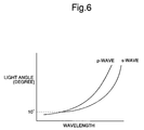
- the backward projection light of the semiconductor laser diode 4 is subdivided into two beams of laser light (namely, transmission light and reflection light) by the wavelength filter 11. Since the projection light of the semiconductor laser diode 4 is propagated as a single polarized wave, this single polarized wave is featured by that this single polarized wave can be hardly influenced by the angle restriction of the wavelength filter 11. In other words, as to the angle of the wavelength filter 11 with respect to the incident light, there is no problem with respect to the incident angle dependent characteristic by the polarized wave as shown in Fig. 6, because the backward light to be entered is propagated by way of the single polarized wave.
- both the position of the wavelength filter 11 and the position of the light receiving device 12 can be freely changed.
- the wavelength monitor portion can be made compact.
- a wavelength multiplexing communication when a large number of optical transmission modules are required, such a compact wavelength monitor portion may have a great merit in view of a space.
- Both the transmission characteristic and the reflection characteristic may be changed by changing the angle of the wavelength filter 11.
- such a cumbersome operation for preparing the different wavelength filters every optical transmission modules can be avoided by mounting the wavelength filter 11, while changing the setting angle of this wavelength filter 11, so that a total amount of these prepared wavelength filters can be suppressed.
- the beam splitter 28 is no longer required, as compared with the structure of the conventional optical transmitter shown in Fig. 1, the present invention is featured by that the optical transmission module can be made compact.
- the optical transmitter of the first embodiment mode in order to stabilize the light output from the semiconductor laser diode 4, the light amounts detected by two light receiving devices 12 and 13 are processed by the calculating device 19, and then the processed light amounts are compared by the comparator 20.
- the LD drive circuit 22 is driven by this comparison result so as to control the semiconductor laser diode 4.
- a light output of the semiconductor laser diode 4 is controlled to become constant based upon a comparison value obtained from a light detection value of one light receiving device 13 and a reference voltage of the comparator 20.
- Fig. 4 is a schematic diagram for showing an arrangement of an optical transmitter according to the second embodiment mode of the present invention. It should be understood that a basic idea about an oscillation wavelength control operation of the semiconductor laser diode 4, and another basic idea about a temperature control operation of a wavelength monitor unit, employed in the optical transmitter of the second embodiment shown in Fig. 4, are similar to those of the first embodiment mode. In this second embodiment mode, backward light which has passed through a wavelength filter 11 is entered into both a light receiving device 12 and another light receiving device 13.
- a current detected by the light receiving device 13 is converted into a voltage by an I-V converter, and then an error signal obtained between the converted voltage and a reference voltage of a comparator 20 is fed back to an LD control circuit 22 in such a manner that this error signal becomes zero.
- a light output level of the semiconductor laser diode 4 is controlled.
- not only no calculating device 19 is used so as to stabilize the light output of the semiconductor laser diode 4, but also the signal detected by the light receiving device 13 is no longer divided, so that there is an advantage that a total number of structural components can be reduced.
- the oscillation wavelength of the semiconductor laser diode can be set and controlled in high precision.
- the wavelengths of the signal light of each wavelength are located close to each other and are controlled in high precision, so that a wavelength multiplexing optical transmission apparatus can be arranged.
- Fig. 5 is a block diagram for representing an arrangement of a wavelength multiplexing optical transmission apparatus with employment of the optical transmitter, according to the present invention.
- the wavelength multiplexing optical transmission apparatus of the present invention is provided with an optical transmission station 100, an optical reception station 200, and an optical transmission path 300.
- the optical transmission path 300 is used to connect the optical transmission station 100 to the optical reception station 200.
- This wavelength multiplexing optical transmission apparatus optically transmits a plurality of signal light having wavelengths different from each other between the optical transmission station 100 and the optical reception station 200.
- the optical transmission station 100 is equipped with a plurality of optical transmitters 101, and a wavelength division multiplexer 110 for wavelength-multiplexing signal light.
- the optical transmitter 101 corresponds to the above-explained optical transmitter of the present invention.
- This optical transmitter 101 outputs such signal light from an optical waveguide (optical fiber), the wavelengths of which are different from each other.
- the optical reception station 200 is equipped with an optical demultiplexer 210 for demultiplexing the received wavelength-multiplexed signal light, and an optical receiver 201 for receiving each of the demultiplexed signal light.
- the oscillation wavelength of the semiconductor laser diode can be set in high precision and also can be controlled, even when more than 100 beams of signal light are wavelength-multiplexed while the oscillation wavelength of the semiconductor laser diode are located, for instance, in a proximate interval from 1 pm to 100 pm in a wavelength range of 1,550 nm, this optical transmitter can perform the optical transmission under stable condition.
- the backward projection light of the semiconductor laser diode is subdivided by 2 by the wavelength filter containing the oscillation wavelength of the semiconductor laser in the wavelength band in which the transmission wavelength band is transferred to the reflection wavelength band.
- both the transmission light and the reflection light which are subdivided from the backward projection light, are received, respectively, so as to detect the light levels of both the transmission light and the reflection light.
- Either the ratio or the difference between the transmission light and the reflection light is calculated based upon these transmission light level and reflection light level. While the calculated ratio, or difference is compared with the reference value, the oscillation wavelength of the semiconductor laser diode is controlled in such a manner that the compared value can be made constant. As a result, the oscillation wavelength of the semiconductor laser is controlled without using the forward projection light and the beam splitter, so that the oscillation wavelength can be stabilized.
- the summation of the transmission light level and the reflection light level is also calculated, and also the injection current to the semiconductor laser diode is controlled. As a consequence, both the light output level and the wavelength can be controlled.
Landscapes
- Physics & Mathematics (AREA)
- Electromagnetism (AREA)
- Engineering & Computer Science (AREA)
- Computer Networks & Wireless Communication (AREA)
- Signal Processing (AREA)
- Semiconductor Lasers (AREA)
- Optical Communication System (AREA)
Abstract
Description
Claims (10)
- A optical transmitter comprising:a semiconductor laser diode;an optical waveguide path into which forward projection light of said semiconductor laser diode is entered;a wavelength filter containing an oscillation wavelength of said semiconductor laser diode in a wavelength band where a transmission wavelength band is transferred to a reflection wavelength band and vice versa, for causing a portion of backward projection light of said semiconductor laser diode to pass therethrough to output transmission light, and for reflecting the remaining light of the backward projection light to output reflection light;a first light receiving device for detecting the light level of the transmission light to output a transmission light level;a second light receiving device for detecting the light level of the reflection light to output a reflection light level; anda wavelength control circuit for controlling the oscillation wavelength of said semiconductor laser diode based upon the transmission light level and the reflection light level.
- An optical transmitter as claimed in claim 1, further comprising:a summation light level calculating circuit for calculating the summation of the transmission light level and the reflection light level; anda projection light control circuit for controlling the light level of said forward projection light based upon the summation light level.
- An optical transmitter as claimed in claim 1 or 2, wherein
said wavelength control circuit includes:a first temperature control element for controlling a peripheral temperature of said semiconductor laser diode; anda first temperature control circuit for controlling said first temperature control element in such a manner that the ratio of the transmission light level to the reflection light level becomes equal to a predetermined reference ratio. - An optical transmitter as claimed in claim 1 or 2, wherein
said wavelength control circuit includes:a first temperature control element for controlling a peripheral temperature of said semiconductor laser diode; anda first temperature control circuit for controlling said first temperature control element in such a manner that the difference between the transmission light level and the reflection light level becomes equal to a predetermined reference value. - An optical transmitter as claimed in claim 1 or 2, wherein
said wavelength control circuit includes:a first temperature control element for controlling a peripheral temperature of said semiconductor laser diode; anda first temperature control circuit for controlling said first temperature control element in such a manner that the difference between the transmission light level and the reflection light level is divided by the summation light level and then the divided difference is ruled to obtain a ruled level difference, and the ruled level difference is made equal to a predetermined reference value. - An optical transmitter as claimed in claim 5, further comprising an injection current control circuit for controlling an injection current to said semiconductor laser diode so as to control the projection light level.
- An optical transmitter as claimed in claim 1 or 2, further comprising:a second temperature control element for controlling a peripheral temperature of said wavelength filter; anda second temperature control circuit for controlling said second temperature control element in such a manner that the peripheral temperature of said wavelength filter becomes constant.
- An optical transmitter as claimed in claim 1 or 2, wherein
said optical waveguide path is an optical fiber. - An optical transmitter as claimed in claim 1 or 2, further comprising:a lens arranged between said semiconductor laser diode and said wavelength filter, for converting the backward projection light into a collimated beam.
- A wavelength multiplexing optical transmission apparatus comprising: an optical transmission station; an optical reception station; and an optical transmission path for connecting said optical transmission station to said optical reception station, for optically transmitting a plurality of signal light having wavelengths different from each other between said optical transmission station and said optical reception station, wherein
said optical transmission station includes:the optical transmitter as recited in claim 1 or 2;a plurality of optical transmitters in which wavelengths of signal light outputted from said optical waveguide paths are different from each other; anda wavelength division multiplexer for wavelength multiplexing said signal light, and wherein
said optical reception station includesan optical receiver for receiving the respective signal light.
Applications Claiming Priority (2)
| Application Number | Priority Date | Filing Date | Title |
|---|---|---|---|
| JP17846799 | 1999-06-24 | ||
| JP11178467A JP2001007438A (en) | 1999-06-24 | 1999-06-24 | Optical transmitter and wavelength multiplexing optical transmission unit employing it |
Publications (2)
| Publication Number | Publication Date |
|---|---|
| EP1063794A2 true EP1063794A2 (en) | 2000-12-27 |
| EP1063794A3 EP1063794A3 (en) | 2004-12-01 |
Family
ID=16049031
Family Applications (1)
| Application Number | Title | Priority Date | Filing Date |
|---|---|---|---|
| EP00113367A Withdrawn EP1063794A3 (en) | 1999-06-24 | 2000-06-23 | Optical transmitter and wavelength multiplexing optical transmission apparatus using the same |
Country Status (3)
| Country | Link |
|---|---|
| EP (1) | EP1063794A3 (en) |
| JP (1) | JP2001007438A (en) |
| CA (1) | CA2312150A1 (en) |
Cited By (7)
| Publication number | Priority date | Publication date | Assignee | Title |
|---|---|---|---|---|
| WO2003015324A1 (en) * | 2001-08-03 | 2003-02-20 | Redfern Broadband Networks, Inc. | Osp hardened wdm network |
| WO2003056736A1 (en) * | 2001-12-21 | 2003-07-10 | Redfern Broadband Networks, Inc. | Wdm add/drop multiplexer module |
| EP1215832A3 (en) * | 2000-12-13 | 2003-08-27 | Nec Corporation | Variable-wavelength optical transmitter with output control and optical communication system thereof |
| US6795316B2 (en) | 2001-12-21 | 2004-09-21 | Redfern Broadband Networks, Inc. | WDM add/drop multiplexer module |
| EP1265379A3 (en) * | 2001-06-07 | 2005-08-17 | The Furukawa Electric Co., Ltd. | Wavelength-stabilised optical transmitter for WDM systems |
| EP1433231A4 (en) * | 2001-10-01 | 2005-10-05 | Sumitomo Electric Industries | Multimode semiconductor laser module, wavelength detector, wavelength stabilizer, and raman amplifier |
| US7651264B2 (en) * | 2002-06-18 | 2010-01-26 | Hamamatsu Photonics K.K. | Laser processing device, laser processing temperature measuring device, laser processing method and laser processing temperature measuring method |
Families Citing this family (11)
| Publication number | Priority date | Publication date | Assignee | Title |
|---|---|---|---|---|
| JP3654170B2 (en) | 2000-09-29 | 2005-06-02 | 日本電気株式会社 | Output monitoring control device and optical communication system |
| WO2002067025A1 (en) * | 2001-02-20 | 2002-08-29 | Sumitomo Osaka Cement Co., Ltd. | Optical resonator and wavelength control module using the resonator |
| JP4844997B2 (en) * | 2001-08-29 | 2011-12-28 | 古河電気工業株式会社 | Laser module |
| JP3895608B2 (en) * | 2002-01-30 | 2007-03-22 | 古河電気工業株式会社 | Optical module, optical transmitter, and WDM optical transmitter |
| EP1624543B1 (en) * | 2003-05-13 | 2010-12-01 | Nippon Telegraph And Telephone Corporation | Optical module and method for monitoring and controlling wavelength |
| JP4533608B2 (en) * | 2003-09-12 | 2010-09-01 | 富士通株式会社 | Tunable laser |
| US7372881B2 (en) | 2003-10-09 | 2008-05-13 | Asahi Kasei Microsystems Co., Ltd. | Semiconductor laser wavelength control device |
| JP4820075B2 (en) * | 2003-10-09 | 2011-11-24 | 旭化成エレクトロニクス株式会社 | Semiconductor laser wavelength controller |
| JP5362169B2 (en) * | 2005-01-31 | 2013-12-11 | 住友電工デバイス・イノベーション株式会社 | LASER DEVICE, OPTICAL DEVICE CONTROL METHOD, AND LASER DEVICE CONTROL METHOD |
| JP2009004525A (en) * | 2007-06-21 | 2009-01-08 | Fujitsu Ltd | Light source module |
| JP2011244018A (en) * | 2011-09-07 | 2011-12-01 | Sumitomo Electric Device Innovations Inc | Laser device, method for controlling optical device, and method for controlling laser device |
Family Cites Families (1)
| Publication number | Priority date | Publication date | Assignee | Title |
|---|---|---|---|---|
| JP2989775B2 (en) * | 1997-01-21 | 1999-12-13 | サンテック株式会社 | Laser light source wavelength stabilizer |
-
1999
- 1999-06-24 JP JP11178467A patent/JP2001007438A/en active Pending
-
2000
- 2000-06-23 EP EP00113367A patent/EP1063794A3/en not_active Withdrawn
- 2000-06-23 CA CA 2312150 patent/CA2312150A1/en not_active Abandoned
Cited By (12)
| Publication number | Priority date | Publication date | Assignee | Title |
|---|---|---|---|---|
| EP1215832A3 (en) * | 2000-12-13 | 2003-08-27 | Nec Corporation | Variable-wavelength optical transmitter with output control and optical communication system thereof |
| US6915035B2 (en) | 2000-12-13 | 2005-07-05 | Nec Corporation | Variable wavelength optical transmitter output control method therefor and optical communication system |
| EP1265379A3 (en) * | 2001-06-07 | 2005-08-17 | The Furukawa Electric Co., Ltd. | Wavelength-stabilised optical transmitter for WDM systems |
| WO2003015324A1 (en) * | 2001-08-03 | 2003-02-20 | Redfern Broadband Networks, Inc. | Osp hardened wdm network |
| EP1433231A4 (en) * | 2001-10-01 | 2005-10-05 | Sumitomo Electric Industries | Multimode semiconductor laser module, wavelength detector, wavelength stabilizer, and raman amplifier |
| US7027473B2 (en) | 2001-10-01 | 2006-04-11 | Sumitomo Electric Industries, Ltd. | Multimode semiconductor laser module, wavelength detector, wavelength stabilizer, and Raman amplifier |
| WO2003056736A1 (en) * | 2001-12-21 | 2003-07-10 | Redfern Broadband Networks, Inc. | Wdm add/drop multiplexer module |
| US6795316B2 (en) | 2001-12-21 | 2004-09-21 | Redfern Broadband Networks, Inc. | WDM add/drop multiplexer module |
| US6804116B2 (en) | 2001-12-21 | 2004-10-12 | Redfern Broadband Networks Inc. | WDM add/drop multiplexer module |
| US6822860B2 (en) | 2001-12-21 | 2004-11-23 | Redfern Broadband Networks Inc. | WDM add/drop multiplexer module |
| US7651264B2 (en) * | 2002-06-18 | 2010-01-26 | Hamamatsu Photonics K.K. | Laser processing device, laser processing temperature measuring device, laser processing method and laser processing temperature measuring method |
| US8727610B2 (en) | 2002-06-18 | 2014-05-20 | Hamamatsu Photonics K.K. | Laser processing apparatus,laser processing temperature measuring apparatus,laser processing method,and laser processing temperature measuring method |
Also Published As
| Publication number | Publication date |
|---|---|
| EP1063794A3 (en) | 2004-12-01 |
| CA2312150A1 (en) | 2000-12-24 |
| JP2001007438A (en) | 2001-01-12 |
Similar Documents
| Publication | Publication Date | Title |
|---|---|---|
| EP1063794A2 (en) | Optical transmitter and wavelength multiplexing optical transmission apparatus using the same | |
| CA2209558C (en) | Wavelength monitoring and control assembly for wdm optical transmission systems | |
| EP1215832B1 (en) | Variable-wavelength optical transmitter with output control and optical communication system thereof | |
| US7450858B2 (en) | Apparatus and method for transmitting and receiving wavelength division multiplexing signals | |
| US6587214B1 (en) | Optical power and wavelength monitor | |
| US6650667B2 (en) | Semiconductor laser apparatus, semiconductor laser module, optical transmitter and wavelength division multiplexing communication system | |
| US7203212B2 (en) | System and method for wavelength error measurement | |
| US5896201A (en) | Optical device for wavelength monitoring and wavelength control | |
| JP2001257419A (en) | Wavelength stabilized laser module | |
| US10103809B2 (en) | Wavelength tunable light source, and optical transceiver using the same | |
| US10670803B2 (en) | Integrated wavelength monitor | |
| JP2000236135A (en) | Self-monitoring light source for optical communication using stable wavelength | |
| US20070104426A1 (en) | Bi-directional optical transceiver | |
| JP2014165384A (en) | Semiconductor laser module | |
| US6567437B1 (en) | Wavelength monitoring device and its adjusting method, and wavelength stabilizing light source and transmission system having plural wavelength stabilizing light source | |
| US7061596B2 (en) | Wavelength-tracking dispersion compensator | |
| JP2001244557A (en) | Wavelength monitoring device, adjustment method thereof, and wavelength stabilized light source | |
| JP4222469B2 (en) | Wavelength monitor and semiconductor laser module | |
| JP2546151B2 (en) | Laser diode emission wavelength controller | |
| EP1324442A2 (en) | Optical semiconductor module | |
| US20030053064A1 (en) | Wavelength detector and optical transmitter | |
| JP2002043686A (en) | Semiconductor laser device, semiconductor laser module and optical transmitter | |
| JP2004119721A (en) | Wavelength locker element |
Legal Events
| Date | Code | Title | Description |
|---|---|---|---|
| PUAI | Public reference made under article 153(3) epc to a published international application that has entered the european phase |
Free format text: ORIGINAL CODE: 0009012 |
|
| AK | Designated contracting states |
Kind code of ref document: A2 Designated state(s): AT BE CH CY DE DK ES FI FR GB GR IE IT LI LU MC NL PT SE |
|
| AX | Request for extension of the european patent |
Free format text: AL;LT;LV;MK;RO;SI |
|
| PUAL | Search report despatched |
Free format text: ORIGINAL CODE: 0009013 |
|
| AK | Designated contracting states |
Kind code of ref document: A3 Designated state(s): AT BE CH CY DE DK ES FI FR GB GR IE IT LI LU MC NL PT SE |
|
| AX | Request for extension of the european patent |
Extension state: AL LT LV MK RO SI |
|
| 17P | Request for examination filed |
Effective date: 20041020 |
|
| AKX | Designation fees paid |
Designated state(s): DE FR GB IT |
|
| 17Q | First examination report despatched |
Effective date: 20080221 |
|
| STAA | Information on the status of an ep patent application or granted ep patent |
Free format text: STATUS: THE APPLICATION IS DEEMED TO BE WITHDRAWN |
|
| 18D | Application deemed to be withdrawn |
Effective date: 20080903 |