EP1063656A2 - Self- supporting cables and an apparatus and methods for making the same - Google Patents
Self- supporting cables and an apparatus and methods for making the same Download PDFInfo
- Publication number
- EP1063656A2 EP1063656A2 EP00202175A EP00202175A EP1063656A2 EP 1063656 A2 EP1063656 A2 EP 1063656A2 EP 00202175 A EP00202175 A EP 00202175A EP 00202175 A EP00202175 A EP 00202175A EP 1063656 A2 EP1063656 A2 EP 1063656A2
- Authority
- EP
- European Patent Office
- Prior art keywords
- forming
- webs
- cable
- sections
- section
- Prior art date
- Legal status (The legal status is an assumption and is not a legal conclusion. Google has not performed a legal analysis and makes no representation as to the accuracy of the status listed.)
- Withdrawn
Links
- 238000000034 method Methods 0.000 title claims abstract description 26
- 230000005540 biological transmission Effects 0.000 claims abstract description 70
- 239000000463 material Substances 0.000 claims abstract description 36
- 239000000155 melt Substances 0.000 claims abstract description 17
- 230000003287 optical effect Effects 0.000 claims abstract description 17
- 238000004519 manufacturing process Methods 0.000 claims abstract description 6
- 239000011248 coating agent Substances 0.000 claims abstract description 5
- 238000000576 coating method Methods 0.000 claims abstract description 5
- 230000001105 regulatory effect Effects 0.000 claims description 16
- 239000013307 optical fiber Substances 0.000 claims description 13
- 239000004020 conductor Substances 0.000 claims description 8
- 238000001125 extrusion Methods 0.000 claims description 7
- 230000015572 biosynthetic process Effects 0.000 claims description 4
- 230000009471 action Effects 0.000 claims description 2
- 239000000835 fiber Substances 0.000 description 25
- 230000000903 blocking effect Effects 0.000 description 12
- 230000008569 process Effects 0.000 description 8
- XLYOFNOQVPJJNP-UHFFFAOYSA-N water Substances O XLYOFNOQVPJJNP-UHFFFAOYSA-N 0.000 description 4
- 229910000831 Steel Inorganic materials 0.000 description 2
- 239000004760 aramid Substances 0.000 description 2
- 229920003235 aromatic polyamide Polymers 0.000 description 2
- 239000002131 composite material Substances 0.000 description 2
- 239000011152 fibreglass Substances 0.000 description 2
- 239000004519 grease Substances 0.000 description 2
- 239000010959 steel Substances 0.000 description 2
- RNFJDJUURJAICM-UHFFFAOYSA-N 2,2,4,4,6,6-hexaphenoxy-1,3,5-triaza-2$l^{5},4$l^{5},6$l^{5}-triphosphacyclohexa-1,3,5-triene Chemical compound N=1P(OC=2C=CC=CC=2)(OC=2C=CC=CC=2)=NP(OC=2C=CC=CC=2)(OC=2C=CC=CC=2)=NP=1(OC=1C=CC=CC=1)OC1=CC=CC=C1 RNFJDJUURJAICM-UHFFFAOYSA-N 0.000 description 1
- NIXOWILDQLNWCW-UHFFFAOYSA-M Acrylate Chemical compound [O-]C(=O)C=C NIXOWILDQLNWCW-UHFFFAOYSA-M 0.000 description 1
- RYGMFSIKBFXOCR-UHFFFAOYSA-N Copper Chemical compound [Cu] RYGMFSIKBFXOCR-UHFFFAOYSA-N 0.000 description 1
- 239000002250 absorbent Substances 0.000 description 1
- 230000008859 change Effects 0.000 description 1
- 150000001875 compounds Chemical class 0.000 description 1
- 238000010276 construction Methods 0.000 description 1
- 238000013270 controlled release Methods 0.000 description 1
- 229910052802 copper Inorganic materials 0.000 description 1
- 239000010949 copper Substances 0.000 description 1
- 230000009977 dual effect Effects 0.000 description 1
- 239000003063 flame retardant Substances 0.000 description 1
- 238000009434 installation Methods 0.000 description 1
- 239000011159 matrix material Substances 0.000 description 1
- 238000012986 modification Methods 0.000 description 1
- 230000004048 modification Effects 0.000 description 1
- 238000005192 partition Methods 0.000 description 1
- 230000002093 peripheral effect Effects 0.000 description 1
- 239000000843 powder Substances 0.000 description 1
- 238000004080 punching Methods 0.000 description 1
- 239000011347 resin Substances 0.000 description 1
- 229920005989 resin Polymers 0.000 description 1
- 238000000926 separation method Methods 0.000 description 1
- 239000000126 substance Substances 0.000 description 1
- 230000007704 transition Effects 0.000 description 1
Images


Classifications
-
- G—PHYSICS
- G02—OPTICS
- G02B—OPTICAL ELEMENTS, SYSTEMS OR APPARATUS
- G02B6/00—Light guides; Structural details of arrangements comprising light guides and other optical elements, e.g. couplings
- G02B6/44—Mechanical structures for providing tensile strength and external protection for fibres, e.g. optical transmission cables
- G02B6/4401—Optical cables
- G02B6/4415—Cables for special applications
- G02B6/4416—Heterogeneous cables
- G02B6/4422—Heterogeneous cables of the overhead type
-
- G—PHYSICS
- G02—OPTICS
- G02B—OPTICAL ELEMENTS, SYSTEMS OR APPARATUS
- G02B6/00—Light guides; Structural details of arrangements comprising light guides and other optical elements, e.g. couplings
- G02B6/44—Mechanical structures for providing tensile strength and external protection for fibres, e.g. optical transmission cables
- G02B6/4479—Manufacturing methods of optical cables
-
- G—PHYSICS
- G02—OPTICS
- G02B—OPTICAL ELEMENTS, SYSTEMS OR APPARATUS
- G02B6/00—Light guides; Structural details of arrangements comprising light guides and other optical elements, e.g. couplings
- G02B6/44—Mechanical structures for providing tensile strength and external protection for fibres, e.g. optical transmission cables
- G02B6/4479—Manufacturing methods of optical cables
- G02B6/4484—Manufacturing methods of optical cables with desired surplus length between fibres and protection features
-
- H—ELECTRICITY
- H01—ELECTRIC ELEMENTS
- H01B—CABLES; CONDUCTORS; INSULATORS; SELECTION OF MATERIALS FOR THEIR CONDUCTIVE, INSULATING OR DIELECTRIC PROPERTIES
- H01B11/00—Communication cables or conductors
- H01B11/22—Cables including at least one electrical conductor together with optical fibres
-
- G—PHYSICS
- G02—OPTICS
- G02B—OPTICAL ELEMENTS, SYSTEMS OR APPARATUS
- G02B6/00—Light guides; Structural details of arrangements comprising light guides and other optical elements, e.g. couplings
- G02B6/44—Mechanical structures for providing tensile strength and external protection for fibres, e.g. optical transmission cables
- G02B6/4401—Optical cables
- G02B6/4405—Optical cables with longitudinally spaced waveguide clamping
-
- G—PHYSICS
- G02—OPTICS
- G02B—OPTICAL ELEMENTS, SYSTEMS OR APPARATUS
- G02B6/00—Light guides; Structural details of arrangements comprising light guides and other optical elements, e.g. couplings
- G02B6/44—Mechanical structures for providing tensile strength and external protection for fibres, e.g. optical transmission cables
- G02B6/4401—Optical cables
- G02B6/441—Optical cables built up from sub-bundles
- G02B6/4411—Matrix structure
-
- G—PHYSICS
- G02—OPTICS
- G02B—OPTICAL ELEMENTS, SYSTEMS OR APPARATUS
- G02B6/00—Light guides; Structural details of arrangements comprising light guides and other optical elements, e.g. couplings
- G02B6/44—Mechanical structures for providing tensile strength and external protection for fibres, e.g. optical transmission cables
- G02B6/4401—Optical cables
- G02B6/4415—Cables for special applications
- G02B6/4416—Heterogeneous cables
-
- G—PHYSICS
- G02—OPTICS
- G02B—OPTICAL ELEMENTS, SYSTEMS OR APPARATUS
- G02B6/00—Light guides; Structural details of arrangements comprising light guides and other optical elements, e.g. couplings
- G02B6/44—Mechanical structures for providing tensile strength and external protection for fibres, e.g. optical transmission cables
- G02B6/4439—Auxiliary devices
- G02B6/4471—Terminating devices ; Cable clamps
- G02B6/4472—Manifolds
- G02B6/4473—Three-way systems
Definitions
- the present invention relates to cables, and an apparatus and methods for making cables, that can include at least one optical fiber.
- Fiber optic cables include at least one optical fiber that can transmit telecommunication information, for example, voice, data, and video information.
- Self-supporting fiber optic cables are designed for aerial applications and typically include a messenger wire and at least one core section having conductors therein that may be solely optical or a combination of optical and electrical conductors.
- Self-supporting fiber optic cables of the figure 8 type may be characterized into two general categories, namely, self-supporting cables with a core section having no excess length relative to the messenger wire, and self-supporting cables having a core section having an over-length, typically about 0.2%, relative to the messenger wire.
- Examples of self-supporting cables having no core section over-length are disclosed in US-A-4449012, US-A-4763983, US-A-5095176, and US-A-5371823.
- Examples of self-supporting cables having a core section over-length are disclosed in US-A-4662712 and US-A-4883671.
- self-supporting cables When installed in a self-supporting application, self-supporting cables may experience a high degree of tension.
- the messenger wire bears most of the tension, thereby supporting the core section, and protecting the optical fibers in the core section from high tensile forces.
- tension acts on the messenger wire however, the messenger wire tends to elongate, which results in an elongation of the core section. Elongation of the core section of a self-supporting fiber optic cable not having an over-length may cause attenuation losses and/or can compromise mechanical reliability of the optical fibers.
- the elongation is, up to the amount of existing over-length of the core section, advantageously taken up by the over-length in the core section whereby the core section may be elongated without potentially causing strain and/or attenuation in the optical fibers.
- US-A-4,467,138 discloses a self-supporting cable with two transmission sections (for example one transmission section containing at least one optical fiber and another transmission section containing electrical conductors) which are enclosed in a jacket and are separable by tearing the jacket along lines of weakness from each other and from a messenger section.
- Such a construction does not readily accommodate over-length in the optical (or the electrical) transmission section, and it may not always tear cleanly in the way intended, risking that one or more of the separated parts may not be adequately protected by the remains of the jacket.
- the present invention provides a self-supporting cable with at least two transmission sections which are enclosed in a jacket and are separable from each other and from a messenger section, characterized in that the jacket comprises at least two webs each of which connects one of the transmission sections to the messenger section or to another transmission section.
- the web (or webs) directly connecting to that section is formed intermittently in a series of longitudinally spaced webs.
- the web might be continuous but in longitudinally alternating sections of substantially different flexibility, typically achieved by varying its thickness. In either case, the aim is to ensure that the over-length is accommodated by forming the section into a controlled undulating profile.
- the extruder cross-head used to manufacture self-supporting cables can be configured to define continuous or intermittent webs for connecting cable sections.
- Web-forming extruder cross-heads include a single plunger, e.g., as is disclosed in JP-46-38748 and JP-8-75969.
- the extruder head includes a melt cavity with a molten jacketing material therein. As the messenger wires and core translate through the melt cavity they are coated with the molten jacketing material. As the messenger wires and core exit the extruder head, a die orifice determines the peripheral shape of the cable jacket therearound, and the orifice includes a web-forming area for the formation of webs.
- the plunger operates by moving into a blocking position in the die orifice between cable sections, physically blocking the molten jacketing material from forming the web.
- the plunger is reciprocated in and out of the blocking position so that the webs are formed intermittently, spaced by longitudinal gaps.
- the cable could be initially formed with continuous webs and at least one intermittent web subsequently formed by punching out or otherwise removing appropriate parts of the web.
- At least one of the webs (for example one which connects a transmission section having electrical conductors only, not optical fibers) is continuous.
- At least two webs are each formed intermittently in distinct series of webs.
- At least some of the cable sections have centers generally aligned in a plane.
- the invention also includes apparatus for making a self-supporting cable with at least two transmission sections which are enclosed in a jacket and are separable from each other and from a messenger section, the apparatus comprising an extruder cross-head including an extrusion die for forming the jacket and characterized in that the die is shaped to form at least two webs each of which connects one of the transmission sections to the messenger section or to another transmission section.
- the invention also provides a method of making a self-supporting cable with at least two transmission sections which are enclosed in a jacket and are separable from each other and from a messenger section comprising placing the transmission sections and a messenger section in parallel spaced formation and extruding a common jacket around them, characterized in that the jacket comprises at least two webs each of which connects one of the transmission sections to the messenger section or to another transmission section.
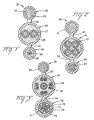
- Fiber optic cable 20 can be a self-supporting cable that is composed of cable sections, for example, a messenger section 22 and transmission sections 26 and 28. Each cable section preferably comprises a portion of a cable jacket 21 having webs 24 that connect cable sections 22, 26, 28 together.
- Messenger section 22 preferably comprises non-metallic and/or metallic strength members, for example, aramid or fiberglass yarns, glass reinforced plastic rods, and/or a steel messenger wire 23.
- Transmission section 26 preferably comprises at least one transmission component, for example, an electrical/electronic component 27.
- Transmission component 27 can be, for example, a twisted pair of electrical wires that are preferably surrounded by a layer of strength members 25. Transmission component 27 preferably performs, for example, a data or power transmission function. Transmission section 28 preferably includes at least one optical fiber, for example, in an optical unit 30. Optical unit 30 preferably comprises at least one single mode, multi-mode, or multi-core optical fiber, and may be surrounded by a layer of strength members 29.
- Strength members 25, 29 preferably comprise filaments, for example, aramid strength members with or without a coating of water blocking grease, or a super-absorbent powder or matrix coating. Alternatively, in lieu of strength members 25, 29 the transmission components can be generally surrounded by a water blocking grease.
- Jacket 21 preferably is formed of, for example, PVC, FRPE, PE, or a UV curable resin, e.g., an acrylate.
- Webs 24 are preferably intermittently formed along the length of the cable and are sized to be ripped manually, or with tools, for separating sections 22, 26, 28.
- Fiber optic cables according to the present invention can include any suitable kind or number of optical transmission components for the transmission of telecommunications information, and/or electrical/electronic transmission components for transmitting telecommunications information and/or power.
- fiber optic cable 40 ( Figure 2) includes a transmission section 46 having more than one pair of twisted wires 47.
- Fiber optic cable 60 ( Figure 3) preferably includes a transmission section 66 comprising a composite of power-transmitting conductors 67 disposed about at least one coaxial electrical conductor 68, and fiber optic cable 80 ( Figures 4-5) preferably includes a transmission section 86 including copper clad steel strength members 87.
- Fiber optic cables according to the present invention can include any suitable kind or number of optical transmission components.
- fiber optic cable 40 can include a transmission section 48 having tight buffered optical fibers 50.
- Fiber optic cable 60 can include a loose tube core comprising a central member 71, an optical component 70 having loose buffered optical fibers 72, a core wrap or water swellable tape 74, and strength members 75.
- fiber optic cable 80 can include a transmission section 88 having an optical component 90 including, for example, a mono-tube with loose and/or bundled optical fibers 91 therein.
- Cable sections 26, 46, 66, 86 can include at least one optical transmission component, and cable sections 28, 48, 68, 88 can include one or more electrical/electronic transmission components.
- each cable jacket 21, 41, 61, 81 can include, for example, intermittent webs 24 or 81 ( Figures 1, 4-6, and 7), continuous webs 44 ( Figure 2), or a combination of a intermittent and continuous webs 63, 64 ( Figure 3).
- Webs 24, 44, 63, 64, 84 can be sized for ease of manual or tool-assisted separation of the respective cable sections.
- the web thickness can be less than about 75% of the diameter/thickness of the largest cable section, preferably less than about 50%, and most preferably less than about 25% thereof.
- fiber optic cables of the present invention can be used in a fiber-to-the-home (FTTH) application ( Figure 6).
- FTTH fiber-to-the-home
- a craftsman would separate messenger section 22 from transmission section 26 by tearing or snipping webs 24.
- strength member 23 of messenger section 22 is mechanically attached to, for example, a house.
- Transmission sections 26, 28 are then dropped to a network interface device N containing, for example, a modem that can be powered by electrical components 27 and optically interconnected with optical transmission component 30.
- extruder cross-head 100 can be used to extrude jacket 21 and webs 24. More specifically, extruder cross-head 100 extrudes molten jacketing material that forms jacket 21 and webs 24 as cable 20 moves along the direction of arrow A ( Figure 7). Extruder cross-head 100 preferably includes a body 101 with a melt cavity therein. The melt cavity receives molten jacketing material from an extruder (not shown), messenger wire 23, strength members 25 with transmission components 27, and strength members 29 with optical unit 30 therein.
- Extruder cross-head 100 preferably includes a die orifice 102 having web forming sections 104 ( Figure 8), a messenger profile area 105, and transmission profile areas 107.
- Transmission profile areas 107 apply the jacketing material to strength members 25, 29 by, for example, a tube-on application combined with a draw down vacuum.
- Messenger profile area 105 applies the jacketing material to messenger wire 23 by, for example, pressure extrusion.
- Extruder head 100 preferably includes at least one gap forming part that performs a gap forming function, for example, a plunger 106 that is movably mounted to body 101 for reciprocating action along the direction of arrow B ( Figure 7).
- Extruder cross-head 100 can include at least two plungers 106 operative to reciprocate between blocking and non-blocking positions with respect to web forming sections 104.
- At least one plunger 106 can include a radius 106a ( Figure 8), adjacent to messenger profile area 105, complementing the outer surface of the messenger portion of jacket 21.
- the advance of plungers 106 can be stopped by respective dowel pins 111 fastened thereto.
- the tip ends of plungers 106 can be received in respective recesses 108 of body 101 ( Figure 8).
- plungers can be located on opposed sides of die orifice 102, for example, one on top and the other on the bottom (not shown).
- the motion of plungers 106 can be operatively interlocked to move in unison, can be operated independently of each other, and/or can be timed to be at the same or different web forming positions to suit the desired web forming need.
- Extruder cross-heads according to the present invention may include more than one pressure regulating device.
- the present invention preferably includes a pressure regulating device 120 ( Figures 5 and 6) attached to extruder cross-head 100 for regulating the pressure in the melt cavity, as described in U.S. Serial. No. 09/280,503 incorporated by reference herein.
- Pressure regulating device 120 is operative to keep the melt cavity pressure substantially constant, i.e., there will be substantially no pressure fluctuation in the melt cavity as plungers 106 are reciprocated between the blocking, i.e., gap-forming, and non-blocking, i.e., web forming, positions.
- pressure-regulating device 120 is preferably controlled in sync therewith to assure uniform jacket thickness.
- plungers 106 and pressure regulating device 120 are preferably operatively connected to motion actuating devices, for example, dual acting pneumatic cylinders (not shown).
- the pneumatic cylinders can be operatively associated with a pneumatic solenoid 112, shown schematically in Figure 7, that can simultaneously control the positions of the motion actuating devices along the directions of arrows B and C.
- Solenoid 112 can be controlled by, for example, a conventional programmable logic controller (PLC) (not shown) that interfaces with a cable length counter (not shown) and is programmed to switch the solenoid based on cable length information received from the length counter.
- PLC programmable logic controller
- the PLC can also be programmed to change the length of webs 24 and/or the longitudinal gaps between webs by driving plungers 106 accordingly.
- the PLC can be programmed to have both plungers in a non-intermittent web-forming mode for forming a cable with continuous webs (Figure 2), one of the plungers can be operated to make intermittent webs with the other plunger forming a continuous web ( Figure 3), or both plungers 106 can be driven to form intermittent webs ( Figures 1, 4-6, and 7).
- solenoid 112 is switched between web-forming and longitudinal gap-forming modes by the PLC, the motion actuating devices can act in parallel to cause plungers 106 and pressure regulating device 120 to be switched at the same time.
- Plungers 106 can be controlled to suit the desired cable design and materials cost requirements.
- the webs can be spaced at generally the same axial locations along the cable, the respective locations of the webs can have a staggered spacing, and/or the sizes/thickness of the webs can be the same or different.
- the method according to the present invention preferably comprises the steps of: pulling messenger wire 23, strength members 25 with transmission components 27, and strength members 29 with optical component 30 therein through a melt cavity having a molten jacketing material therein; defining messenger section 22 and transmission sections 26, 28 by coating the messenger wire 23, strength members 25, and strength members 29 with the molten jacketing material; and forming webs between at least respective cable sections 22, 26, 28.
- any of the cable sections can be formed with an over-length, for example, by conventional parameter control methods including the application of tension or velocity differential methods.
- tension to cable components can stretch the components relative to the messenger wire so that after release of the tension the stretched components relax and have an over-length relative to the messenger wire.
- the cable components are fed at a faster speed relative to the messenger wire thereby creating an over-length with respect thereto.
- Transmission sections could have different amounts of over-length relative to each other and with respect to the messenger wire.
- Transition section profile area 107 applies the jacketing material by a tube-on process including application of a vacuum to draw jacket 21 tightly against strength members 25, 29.
- Messenger profile area 105 applies the jacketing material to messenger wire 23 by a pressure extrusion process whereby the interstices between the wire strands are preferably completely filled with jacketing material.
- Cable sections 22, 26, 28 of fiber optic cable 20 emerge from the outlet side of extruder cross-head 100 for further processing down the line.
- Webs 24 are monolithically and intermittently formed as part of jacket 21 during the process. Velocity differential and/or release of tension on the cable sections can result in an over-length relative to messenger wire 23.
- the molten jacketing material is expressed into web-forming sections 104 thereby forming webs 24.
- solenoid 112 requires the motion actuating devices to position plungers 106 such that the plungers are retracted from web forming sections 104, and pressure regulating device 120 is inactive.
- the jacketing material inside the melt cavity experiences an initial melt cavity pressure.
- webs 24 are made intermittently along the length of fiber optic cable 20.
- solenoid 112 is repeatedly switched from the web-forming mode to the gap-forming mode and back again according to a program in the PLC.
- Webs 24 are formed in more than one web series between respective cable sections, for example, series S1, S2 ( Figure 7), and a web series may include a single continuous web S3 ( Figure 2).
- the gap-forming mode requires plungers 106 to be in the blocking position, and pressure regulating device 120 to be in a position to relieve pressure in the melt cavity by releasing molten jacketing material for the interval of time that the gaps are being formed.
- the purpose of pressure regulating device 120 is to maintain the pressure in the melt cavity at substantially the initial melt cavity pressure during the gap-forming mode. To accomplish this purpose, jacketing material will be released by pressure regulating device 120 during formation of the longitudinal gaps.
- an amount of molten jacketing material can be released by pressure regulating device 120 sufficient to avoid a substantial increase in melt cavity pressure.
- the amount of expressed material can be roughly equal to the volume of material that would fill the longitudinal gaps if the plunger was not used.
- the amount of jacketing compound that is released to avoid the increase in pressure can depend upon process and extruder cross-head variables, to name a few, the physical characteristics of the jacketing material (e.g. viscosity and density), melt cavity temperature and pressure, and product line speed.
- the PLC program controls the intervals of time during which the web-forming and gap-forming modes are operative.
- the controlled release of jacketing material from the melt cavity by pressure regulating device 120 avoids substantial pressure fluctuations. Where the webs are formed continuously pressure regulating device 120 need not be activated.
- the methods of the present invention can be applied to make fiber optic cables with webs formed continuously, intermittently, or both, and with substantially uniform cross sectional jacket thicknesses.
- the present invention has been described with reference to the foregoing exemplary embodiments, which embodiments are intended to be illustrative of the present inventive concepts rather than limiting. Persons of ordinary skill in the art will appreciate that variations and modifications of the foregoing embodiments may be made without departing from the scope of the appended claims.
- the concepts described herein can be applied to, for example, opto/electronic composite, buried, indoor, and indoor/outdoor cable applications.
- the concepts described herein can be applied to cables including metallic conductors without optical components, for example, a cable with a twisted pair in one transmission section and a coaxial cable in another transmission section. Any cable section can include an armor layer, more than one messenger section can be used, and a messenger section can be located adjacent or between any transmission section.
- the cable sections preferably have centers thereof generally aligned in a plane, or the cable sections can be offset, for example, the cable sections can be connected in V-shaped, L-shaped or triangular configurations, e.g., each section can be connected to two other cable sections, so that at least some of the cable section centers are in a common plane.
- Flame retardant jacket materials can be selected to achieve, plenum, riser, or LSZH flame ratings. Water absorbing or blocking substances may be included in any interstice in accordance with application requirements.
- the geometry of the webs shown in the drawing figures is exemplary, other web geometries may be used, for example, notches, grooves, arcuate surfaces, or any other suitable shape for attaining a balance between strength in connecting the cable sections are ease of separability during installation.
- the methods of the present invention can include the steps of forming the messenger section jacket by a tube-on process with a draw down vacuum, and applying the transmission section jackets by pressure extrusion.
- the step of forming the messenger and transmission section jackets can include the same method of applying the jacketing material.
- the gap forming parts can be other than plungers, for example, they can be gates, blades, pins, disks, vanes, partitions, or plugs and can be associated with power or motion transmitting components in lieu of or in addition to the cylinders, for example, bearings, rocker arms, cams, gears, electrical components, and/or linkages.
- the cable sections can be marked according to any suitable marking scheme, for example, indent marking with or without tape, sequential marking, and/or co-extrusion striping.
Landscapes
- Physics & Mathematics (AREA)
- General Physics & Mathematics (AREA)
- Optics & Photonics (AREA)
- Engineering & Computer Science (AREA)
- Manufacturing & Machinery (AREA)
- Extrusion Moulding Of Plastics Or The Like (AREA)
- Manufacturing Of Electric Cables (AREA)
- Insulated Conductors (AREA)
- Communication Cables (AREA)
Abstract
Description
Claims (24)
- A self-supporting cable with at least two transmission sections which are enclosed in a jacket and are separable from each other and from a messenger section, characterized in that the jacket comprises at least two webs each of which connects one of the transmission sections to the messenger section or to another transmission section.
- A self-supporting cable as claimed in claim 1 in which at least one of the transmission sections has over-length.
- A self-supporting cable as claimed in claim 2 in which the section having over-length contains at least one optical fiber.
- A self-supporting cable as claimed in any one of claims 1-3 in which at least one of the webs is formed intermittently in a series of webs.
- A self-supporting cable as claimed in any one of claims 1-4 in which at least one of said webs is continuous.
- A self-supporting cable as claimed in any one of claims 1-3 in which at least two webs are each formed intermittently in distinct series of webs.
- A self-supporting cable as claimed in any one of claims 1-6 in which at least one of the transmission sections comprises an electrical/electronic transmission component.
- A self-supporting cable as claimed in claim 1 or claim 2 or in any one of claims 4-7 in which at least one of the transmission sections comprises an optical transmission component.
- A self-supporting cable as claimed in any one of claim 1-8 in which at least one of the transmission sections includes electrical conductors only.
- A Self-supporting cable as claimed in any one of claims 1-9 in which at least some of said cable sections have centers generally aligned in a plane.
- Apparatus for making a self-supporting cable with at least two transmission sections which are enclosed in a jacket and are separable from each other and from a messenger section, the apparatus comprising an extruder cross-head including an extrusion die for forming the jacket and characterized in that the die is shaped to form at least two webs each of which connects one of the transmission sections to the messenger section or to another transmission section.
- Apparatus as claimed in claim 11 comprising: a melt cavity associated with a die orifice comprising web-forming sections for forming distinct webs between cable sections;at least one gap forming part associated with at least one of said web-forming sections, said gap forming part being operative to block the flow of said cable jacketing material for forming webs between at least two of said cable sections.
- Apparatus as claimed in claim 12 in which said gap forming parts comprise a plunger.
- Apparatus as claimed in claim 12 or claim 13 in which a second gap forming part is associated with another of said web-forming sections.
- Apparatus as claimed in any one of claims 12-14 in which said gap forming part is mounted to said apparatus for reciprocating action with respect to said at least one web-forming section.
- Apparatus as claimed in any one of claims 12-15 in which the said gap forming part is operatively associated with a pressure regulating device in communication with said melt cavity for regulating the pressure of said melt cavity.
- A method of making a self-supporting cable with at least two transmission sections which are enclosed in a jacket and are separable from each other and from a messenger section comprising placing the transmission sections and a messenger section in parallel spaced formation and extruding a common jacket around them, characterized in that the jacket comprises at least two webs each of which connects one of the transmission sections to the messenger section or to another transmission section.
- A method as claimed in claim 17 comprising the steps of:(a) pulling cable components through a melt cavity having a molten jacketing material therein;(b) defining at least three cable sections by coating the cable components with said molten jacketing material;(c) monolithically forming at least two series of connecting webs made of said molten jacketing material between each said cable section during a web-forming mode; and(d) defining intermittent webs by forming longitudinal gaps in at least one of said series of webs during a gap-forming mode by switching between said web-forming and gap-forming modes.
- A method as claimed in claim 18, comprising the step of regulating the pressure of said molten jacketing material to minimize pressure fluctuations during the gap-forming mode.
- A method as claimed in claim 18 or claim 19 in which the step of forming respective gaps in said at least one series of webs is performed by a gap-forming part that blocks the flow of said molten jacketing material.
- A method as claimed in claim 18 or claim 19 in which the step of forming said connecting webs is performed by retracting a gap-forming part from said melt cavity.
- A method as claimed in any one of claims 17-21 in which the step of forming at least one of said cable sections includes pressure extrusion of said molten jacketing material.
- A method as claimed in any one of claims 17-21 in which the step of forming at least one of said cable sections includes tubing-on and drawing down said molten jacketing material with a vacuum.
- A method as claimed in claim 18 in which the step of defining intermittent webs by forming longitudinal gaps comprises forming intermittent webs in at least two of said series of webs.
Applications Claiming Priority (2)
| Application Number | Priority Date | Filing Date | Title |
|---|---|---|---|
| US344151 | 1999-06-24 | ||
| US09/344,151 US6563990B1 (en) | 1998-06-22 | 1999-06-24 | Self-supporting cables and an apparatus and methods for making the same |
Publications (2)
| Publication Number | Publication Date |
|---|---|
| EP1063656A2 true EP1063656A2 (en) | 2000-12-27 |
| EP1063656A3 EP1063656A3 (en) | 2002-07-31 |
Family
ID=23349275
Family Applications (1)
| Application Number | Title | Priority Date | Filing Date |
|---|---|---|---|
| EP00202175A Withdrawn EP1063656A3 (en) | 1999-06-24 | 2000-06-22 | Self- supporting cables and an apparatus and methods for making the same |
Country Status (4)
| Country | Link |
|---|---|
| US (2) | US6563990B1 (en) |
| EP (1) | EP1063656A3 (en) |
| JP (1) | JP2001057115A (en) |
| CA (1) | CA2309377A1 (en) |
Cited By (6)
| Publication number | Priority date | Publication date | Assignee | Title |
|---|---|---|---|---|
| ES2325566A1 (en) * | 2007-11-08 | 2009-09-08 | Nordix S.A. | Siames hybrid cable of triple connection for transmission of television, voice and data signals. (Machine-translation by Google Translate, not legally binding) |
| ES2325943A1 (en) * | 2007-12-17 | 2009-09-24 | Nordix, S.A | Cable hybrid siames de seguridad (Machine-translation by Google Translate, not legally binding) |
| WO2015198017A1 (en) * | 2014-06-26 | 2015-12-30 | British Telecommunications Public Limited Company | Cable connections |
| US10892822B2 (en) | 2017-02-01 | 2021-01-12 | British Telecommunications Public Limited Company | Optical fiber event location |
| US20210241936A1 (en) * | 2020-02-04 | 2021-08-05 | Structured Home Wiring Direct, LLC | Composite Hybrid Cables and Methods of Manufacturing and Installing the Same |
| US11274990B2 (en) | 2017-07-20 | 2022-03-15 | British Telecommunications Public Limited Company | Optical fiber |
Families Citing this family (228)
| Publication number | Priority date | Publication date | Assignee | Title |
|---|---|---|---|---|
| BRPI0206428B1 (en) * | 2001-11-19 | 2017-11-28 | Prysmian Cables & Systems Limited | FIBER OPTICAL TRANSMISSION CABLE FOR SUSPENSION INSTALLATION, AND TRANSMISSION INSTALLATION |
| KR100496452B1 (en) * | 2002-11-18 | 2005-06-20 | 엘에스전선 주식회사 | Hybrid cable for communication |
| US6928217B2 (en) * | 2003-07-18 | 2005-08-09 | Corning Cable Systems Llc | Fiber optic cable having a strength member |
| US7184634B2 (en) * | 2004-03-25 | 2007-02-27 | Corning Cable Systems, Llc. | Fiber optic drop cables suitable for outdoor fiber to the subscriber applications |
| US7035513B2 (en) * | 2004-03-25 | 2006-04-25 | Corning Cable Systems Llc | Fiber optic drop cables suitable for outdoor fiber to the subscriber applications |
| US7206482B2 (en) * | 2004-03-25 | 2007-04-17 | Corning Cable Systems, Llc. | Protective casings for optical fibers |
| US7218821B2 (en) * | 2004-08-20 | 2007-05-15 | Furukawa Electric North America Inc. | Optical fiber cables |
| US7206481B2 (en) * | 2004-12-21 | 2007-04-17 | Corning Cable Systems, Llc. | Fiber optic cables manufactured as an assembly and method for manufacturing the same |
| US7079734B2 (en) * | 2004-12-22 | 2006-07-18 | Corning Cable Systems Llc | Fiber optic drop cables suitable for fiber to the subscriber applications |
| US7310430B1 (en) * | 2006-06-02 | 2007-12-18 | Sbc Knowledge Ventures | Hybrid cables for communication networks |
| US7490996B2 (en) * | 2006-08-16 | 2009-02-17 | Sigmund Sommer | Electro-optical plug and receptacle |
| US8203074B2 (en) * | 2006-10-25 | 2012-06-19 | Advanced Technology Holdings Ltd. | Messenger supported overhead cable for electrical transmission |
| US7672556B2 (en) * | 2007-05-24 | 2010-03-02 | Nexans | Flat design composite drop fiber cable with mid-span access capability |
| FR2931253B1 (en) * | 2008-05-16 | 2010-08-20 | Draka Comteq France Sa | FIBER OPTIC TELECOMMUNICATION CABLE |
| US7702203B1 (en) * | 2008-10-30 | 2010-04-20 | Corning Cable Systems Llc | Armored fiber optic assemblies and methods of making the same |
| US20100109174A1 (en) | 2008-11-05 | 2010-05-06 | George Cornelius Abernathy | Method for drop cable having an oval cavity |
| AU2009322446A1 (en) | 2008-12-02 | 2011-06-30 | Corning Cable Systems Llc | Optical fiber array cables and associated fiber optic cables and systems |
| EP2404393B1 (en) | 2009-03-05 | 2018-08-08 | ADC Telecommunications, INC. | Methods, systems and devices for integrating wireless technology into a fiber optic network |
| US8463095B2 (en) | 2009-04-09 | 2013-06-11 | Corning Cable Systems Llc | Armored fiber optic assemblies and methods of forming fiber optic assemblies |
| US20100278492A1 (en) * | 2009-04-30 | 2010-11-04 | Bohler Gregory B | Armored Fiber Optic Assemblies and Methods of Forming Fiber Optic Assemblies |
| US8515236B2 (en) * | 2009-06-09 | 2013-08-20 | Corning Cable Systems Llc | Fiber optic drop cable assembly for deployment on building walls |
| US8331748B2 (en) | 2009-09-30 | 2012-12-11 | Corning Cable Systems Llc | Armored fiber optic assemblies and methods employing bend-resistant multimode fiber |
| US8837940B2 (en) | 2010-04-14 | 2014-09-16 | Adc Telecommunications, Inc. | Methods and systems for distributing fiber optic telecommunication services to local areas and for supporting distributed antenna systems |
| US9078287B2 (en) | 2010-04-14 | 2015-07-07 | Adc Telecommunications, Inc. | Fiber to the antenna |
| US9170390B2 (en) | 2010-04-23 | 2015-10-27 | Corning Cable Systems Llc | Armored fiber optic assemblies and methods of forming fiber optic assemblies |
| US20120145453A1 (en) * | 2010-12-14 | 2012-06-14 | General Cable Technologies Corporation | Power cable with microduct |
| US9165698B2 (en) | 2011-02-24 | 2015-10-20 | Lake Cable, Llc | Cable assembly and method of making a cable assembly |
| US9419321B2 (en) | 2011-08-12 | 2016-08-16 | Commscope Technologies Llc | Self-supporting stripline RF transmission cable |
| US9412495B1 (en) | 2011-10-07 | 2016-08-09 | Encore Wire Corporation | Wire and cable having integrally formed jacket and partitioned wall members and process and apparatus for making the same |
| JP5391296B2 (en) * | 2012-03-02 | 2014-01-15 | 株式会社フジクラ | Optical fiber tape core and optical fiber cable storing the optical fiber core |
| US9679681B2 (en) * | 2012-04-27 | 2017-06-13 | Corning Optical Communications LLC | Hybrid cable including fiber-optic and electrical-conductor elements |
| US10009065B2 (en) | 2012-12-05 | 2018-06-26 | At&T Intellectual Property I, L.P. | Backhaul link for distributed antenna system |
| US9113347B2 (en) | 2012-12-05 | 2015-08-18 | At&T Intellectual Property I, Lp | Backhaul link for distributed antenna system |
| WO2014197103A2 (en) | 2013-03-18 | 2014-12-11 | Adc Telecommunications, Inc. | Architecture for a wireless network |
| US9557505B2 (en) | 2013-03-18 | 2017-01-31 | Commscope Technologies Llc | Power and optical fiber interface |
| CN103165244B (en) * | 2013-03-19 | 2016-01-13 | 江苏亨通线缆科技有限公司 | There is the telecommunication cable of waterproof, anti-interference function |
| CN103219087A (en) * | 2013-04-10 | 2013-07-24 | 江苏通鼎光电科技有限公司 | Self-support digital communication cable |
| CN105247627B (en) | 2013-05-14 | 2018-08-10 | 阿德斯电信公司 | Power/Fiber Optic Hybrid Cable |
| US9525524B2 (en) | 2013-05-31 | 2016-12-20 | At&T Intellectual Property I, L.P. | Remote distributed antenna system |
| US9999038B2 (en) | 2013-05-31 | 2018-06-12 | At&T Intellectual Property I, L.P. | Remote distributed antenna system |
| US8897697B1 (en) | 2013-11-06 | 2014-11-25 | At&T Intellectual Property I, Lp | Millimeter-wave surface-wave communications |
| US9209902B2 (en) | 2013-12-10 | 2015-12-08 | At&T Intellectual Property I, L.P. | Quasi-optical coupler |
| CN103943217B (en) * | 2014-04-26 | 2016-06-15 | 芜湖航天特种电缆厂 | Parallel cable |
| US9530539B2 (en) * | 2014-08-18 | 2016-12-27 | Craig M Joyce | Readily strippable cable |
| US9545743B2 (en) * | 2014-08-18 | 2017-01-17 | Craig M Joyce | Readily strippable cable |
| US9692101B2 (en) | 2014-08-26 | 2017-06-27 | At&T Intellectual Property I, L.P. | Guided wave couplers for coupling electromagnetic waves between a waveguide surface and a surface of a wire |
| US9768833B2 (en) | 2014-09-15 | 2017-09-19 | At&T Intellectual Property I, L.P. | Method and apparatus for sensing a condition in a transmission medium of electromagnetic waves |
| US10063280B2 (en) | 2014-09-17 | 2018-08-28 | At&T Intellectual Property I, L.P. | Monitoring and mitigating conditions in a communication network |
| US9628854B2 (en) | 2014-09-29 | 2017-04-18 | At&T Intellectual Property I, L.P. | Method and apparatus for distributing content in a communication network |
| US9615269B2 (en) | 2014-10-02 | 2017-04-04 | At&T Intellectual Property I, L.P. | Method and apparatus that provides fault tolerance in a communication network |
| US9685992B2 (en) | 2014-10-03 | 2017-06-20 | At&T Intellectual Property I, L.P. | Circuit panel network and methods thereof |
| US9503189B2 (en) | 2014-10-10 | 2016-11-22 | At&T Intellectual Property I, L.P. | Method and apparatus for arranging communication sessions in a communication system |
| US9973299B2 (en) | 2014-10-14 | 2018-05-15 | At&T Intellectual Property I, L.P. | Method and apparatus for adjusting a mode of communication in a communication network |
| US9762289B2 (en) | 2014-10-14 | 2017-09-12 | At&T Intellectual Property I, L.P. | Method and apparatus for transmitting or receiving signals in a transportation system |
| US9653770B2 (en) | 2014-10-21 | 2017-05-16 | At&T Intellectual Property I, L.P. | Guided wave coupler, coupling module and methods for use therewith |
| US9564947B2 (en) | 2014-10-21 | 2017-02-07 | At&T Intellectual Property I, L.P. | Guided-wave transmission device with diversity and methods for use therewith |
| US9780834B2 (en) | 2014-10-21 | 2017-10-03 | At&T Intellectual Property I, L.P. | Method and apparatus for transmitting electromagnetic waves |
| US9627768B2 (en) | 2014-10-21 | 2017-04-18 | At&T Intellectual Property I, L.P. | Guided-wave transmission device with non-fundamental mode propagation and methods for use therewith |
| US9577306B2 (en) | 2014-10-21 | 2017-02-21 | At&T Intellectual Property I, L.P. | Guided-wave transmission device and methods for use therewith |
| US9520945B2 (en) | 2014-10-21 | 2016-12-13 | At&T Intellectual Property I, L.P. | Apparatus for providing communication services and methods thereof |
| US9769020B2 (en) | 2014-10-21 | 2017-09-19 | At&T Intellectual Property I, L.P. | Method and apparatus for responding to events affecting communications in a communication network |
| US9312919B1 (en) | 2014-10-21 | 2016-04-12 | At&T Intellectual Property I, Lp | Transmission device with impairment compensation and methods for use therewith |
| US9680670B2 (en) | 2014-11-20 | 2017-06-13 | At&T Intellectual Property I, L.P. | Transmission device with channel equalization and control and methods for use therewith |
| US10505248B2 (en) | 2014-11-20 | 2019-12-10 | At&T Intellectual Property I, L.P. | Communication cable having a plurality of uninsulated conductors forming interstitial areas for propagating electromagnetic waves therein and method of use |
| US10243784B2 (en) | 2014-11-20 | 2019-03-26 | At&T Intellectual Property I, L.P. | System for generating topology information and methods thereof |
| US9461706B1 (en) | 2015-07-31 | 2016-10-04 | At&T Intellectual Property I, Lp | Method and apparatus for exchanging communication signals |
| US10009067B2 (en) | 2014-12-04 | 2018-06-26 | At&T Intellectual Property I, L.P. | Method and apparatus for configuring a communication interface |
| US10340573B2 (en) | 2016-10-26 | 2019-07-02 | At&T Intellectual Property I, L.P. | Launcher with cylindrical coupling device and methods for use therewith |
| US9544006B2 (en) | 2014-11-20 | 2017-01-10 | At&T Intellectual Property I, L.P. | Transmission device with mode division multiplexing and methods for use therewith |
| US10505252B2 (en) | 2014-11-20 | 2019-12-10 | At&T Intellectual Property I, L.P. | Communication system having a coupler for guiding electromagnetic waves through interstitial areas formed by a plurality of stranded uninsulated conductors and method of use |
| US9954287B2 (en) | 2014-11-20 | 2018-04-24 | At&T Intellectual Property I, L.P. | Apparatus for converting wireless signals and electromagnetic waves and methods thereof |
| US10505250B2 (en) | 2014-11-20 | 2019-12-10 | At&T Intellectual Property I, L.P. | Communication system having a cable with a plurality of stranded uninsulated conductors forming interstitial areas for propagating guided wave modes therein and methods of use |
| US10411920B2 (en) | 2014-11-20 | 2019-09-10 | At&T Intellectual Property I, L.P. | Methods and apparatus for inducing electromagnetic waves within pathways of a cable |
| US9654173B2 (en) | 2014-11-20 | 2017-05-16 | At&T Intellectual Property I, L.P. | Apparatus for powering a communication device and methods thereof |
| US10554454B2 (en) | 2014-11-20 | 2020-02-04 | At&T Intellectual Property I, L.P. | Methods and apparatus for inducing electromagnetic waves in a cable |
| US9800327B2 (en) | 2014-11-20 | 2017-10-24 | At&T Intellectual Property I, L.P. | Apparatus for controlling operations of a communication device and methods thereof |
| US11025460B2 (en) | 2014-11-20 | 2021-06-01 | At&T Intellectual Property I, L.P. | Methods and apparatus for accessing interstitial areas of a cable |
| US9742462B2 (en) | 2014-12-04 | 2017-08-22 | At&T Intellectual Property I, L.P. | Transmission medium and communication interfaces and methods for use therewith |
| US10505249B2 (en) | 2014-11-20 | 2019-12-10 | At&T Intellectual Property I, L.P. | Communication system having a cable with a plurality of stranded uninsulated conductors forming interstitial areas for guiding electromagnetic waves therein and method of use |
| US9997819B2 (en) | 2015-06-09 | 2018-06-12 | At&T Intellectual Property I, L.P. | Transmission medium and method for facilitating propagation of electromagnetic waves via a core |
| US10516555B2 (en) | 2014-11-20 | 2019-12-24 | At&T Intellectual Property I, L.P. | Methods and apparatus for creating interstitial areas in a cable |
| US9329347B1 (en) | 2014-12-11 | 2016-05-03 | Google Inc. | Adjustable clamp sleeve for breakaway bundled interlocking drop fiber |
| US9335501B1 (en) | 2014-12-11 | 2016-05-10 | Google Inc. | Breakaway bundled interlocking drop fiber |
| US10144036B2 (en) | 2015-01-30 | 2018-12-04 | At&T Intellectual Property I, L.P. | Method and apparatus for mitigating interference affecting a propagation of electromagnetic waves guided by a transmission medium |
| US9715073B1 (en) * | 2015-02-19 | 2017-07-25 | Afl Telecommunications Llc | Optical trunk cable having web-connected sub-unitized configuration |
| US9876570B2 (en) | 2015-02-20 | 2018-01-23 | At&T Intellectual Property I, Lp | Guided-wave transmission device with non-fundamental mode propagation and methods for use therewith |
| US9749013B2 (en) | 2015-03-17 | 2017-08-29 | At&T Intellectual Property I, L.P. | Method and apparatus for reducing attenuation of electromagnetic waves guided by a transmission medium |
| US9705561B2 (en) | 2015-04-24 | 2017-07-11 | At&T Intellectual Property I, L.P. | Directional coupling device and methods for use therewith |
| US10224981B2 (en) | 2015-04-24 | 2019-03-05 | At&T Intellectual Property I, Lp | Passive electrical coupling device and methods for use therewith |
| US9793954B2 (en) | 2015-04-28 | 2017-10-17 | At&T Intellectual Property I, L.P. | Magnetic coupling device and methods for use therewith |
| US9948354B2 (en) | 2015-04-28 | 2018-04-17 | At&T Intellectual Property I, L.P. | Magnetic coupling device with reflective plate and methods for use therewith |
| US9871282B2 (en) | 2015-05-14 | 2018-01-16 | At&T Intellectual Property I, L.P. | At least one transmission medium having a dielectric surface that is covered at least in part by a second dielectric |
| US9490869B1 (en) | 2015-05-14 | 2016-11-08 | At&T Intellectual Property I, L.P. | Transmission medium having multiple cores and methods for use therewith |
| US9748626B2 (en) | 2015-05-14 | 2017-08-29 | At&T Intellectual Property I, L.P. | Plurality of cables having different cross-sectional shapes which are bundled together to form a transmission medium |
| US10679767B2 (en) | 2015-05-15 | 2020-06-09 | At&T Intellectual Property I, L.P. | Transmission medium having a conductive material and methods for use therewith |
| US10650940B2 (en) | 2015-05-15 | 2020-05-12 | At&T Intellectual Property I, L.P. | Transmission medium having a conductive material and methods for use therewith |
| US9917341B2 (en) | 2015-05-27 | 2018-03-13 | At&T Intellectual Property I, L.P. | Apparatus and method for launching electromagnetic waves and for modifying radial dimensions of the propagating electromagnetic waves |
| US9866309B2 (en) | 2015-06-03 | 2018-01-09 | At&T Intellectual Property I, Lp | Host node device and methods for use therewith |
| US9912381B2 (en) | 2015-06-03 | 2018-03-06 | At&T Intellectual Property I, Lp | Network termination and methods for use therewith |
| US10103801B2 (en) | 2015-06-03 | 2018-10-16 | At&T Intellectual Property I, L.P. | Host node device and methods for use therewith |
| US10348391B2 (en) | 2015-06-03 | 2019-07-09 | At&T Intellectual Property I, L.P. | Client node device with frequency conversion and methods for use therewith |
| US10154493B2 (en) | 2015-06-03 | 2018-12-11 | At&T Intellectual Property I, L.P. | Network termination and methods for use therewith |
| US10812174B2 (en) | 2015-06-03 | 2020-10-20 | At&T Intellectual Property I, L.P. | Client node device and methods for use therewith |
| US9913139B2 (en) | 2015-06-09 | 2018-03-06 | At&T Intellectual Property I, L.P. | Signal fingerprinting for authentication of communicating devices |
| US9608692B2 (en) | 2015-06-11 | 2017-03-28 | At&T Intellectual Property I, L.P. | Repeater and methods for use therewith |
| US10142086B2 (en) | 2015-06-11 | 2018-11-27 | At&T Intellectual Property I, L.P. | Repeater and methods for use therewith |
| US9820146B2 (en) | 2015-06-12 | 2017-11-14 | At&T Intellectual Property I, L.P. | Method and apparatus for authentication and identity management of communicating devices |
| US9667317B2 (en) | 2015-06-15 | 2017-05-30 | At&T Intellectual Property I, L.P. | Method and apparatus for providing security using network traffic adjustments |
| US9640850B2 (en) | 2015-06-25 | 2017-05-02 | At&T Intellectual Property I, L.P. | Methods and apparatus for inducing a non-fundamental wave mode on a transmission medium |
| US9509415B1 (en) | 2015-06-25 | 2016-11-29 | At&T Intellectual Property I, L.P. | Methods and apparatus for inducing a fundamental wave mode on a transmission medium |
| US9865911B2 (en) | 2015-06-25 | 2018-01-09 | At&T Intellectual Property I, L.P. | Waveguide system for slot radiating first electromagnetic waves that are combined into a non-fundamental wave mode second electromagnetic wave on a transmission medium |
| US9628116B2 (en) | 2015-07-14 | 2017-04-18 | At&T Intellectual Property I, L.P. | Apparatus and methods for transmitting wireless signals |
| US10033108B2 (en) | 2015-07-14 | 2018-07-24 | At&T Intellectual Property I, L.P. | Apparatus and methods for generating an electromagnetic wave having a wave mode that mitigates interference |
| US9836957B2 (en) | 2015-07-14 | 2017-12-05 | At&T Intellectual Property I, L.P. | Method and apparatus for communicating with premises equipment |
| US9882257B2 (en) | 2015-07-14 | 2018-01-30 | At&T Intellectual Property I, L.P. | Method and apparatus for launching a wave mode that mitigates interference |
| US9722318B2 (en) | 2015-07-14 | 2017-08-01 | At&T Intellectual Property I, L.P. | Method and apparatus for coupling an antenna to a device |
| US10033107B2 (en) | 2015-07-14 | 2018-07-24 | At&T Intellectual Property I, L.P. | Method and apparatus for coupling an antenna to a device |
| US9847566B2 (en) | 2015-07-14 | 2017-12-19 | At&T Intellectual Property I, L.P. | Method and apparatus for adjusting a field of a signal to mitigate interference |
| US10148016B2 (en) | 2015-07-14 | 2018-12-04 | At&T Intellectual Property I, L.P. | Apparatus and methods for communicating utilizing an antenna array |
| US10320586B2 (en) | 2015-07-14 | 2019-06-11 | At&T Intellectual Property I, L.P. | Apparatus and methods for generating non-interfering electromagnetic waves on an insulated transmission medium |
| US10170840B2 (en) | 2015-07-14 | 2019-01-01 | At&T Intellectual Property I, L.P. | Apparatus and methods for sending or receiving electromagnetic signals |
| US10341142B2 (en) | 2015-07-14 | 2019-07-02 | At&T Intellectual Property I, L.P. | Apparatus and methods for generating non-interfering electromagnetic waves on an uninsulated conductor |
| US10044409B2 (en) | 2015-07-14 | 2018-08-07 | At&T Intellectual Property I, L.P. | Transmission medium and methods for use therewith |
| US9853342B2 (en) | 2015-07-14 | 2017-12-26 | At&T Intellectual Property I, L.P. | Dielectric transmission medium connector and methods for use therewith |
| US10205655B2 (en) | 2015-07-14 | 2019-02-12 | At&T Intellectual Property I, L.P. | Apparatus and methods for communicating utilizing an antenna array and multiple communication paths |
| US9608740B2 (en) | 2015-07-15 | 2017-03-28 | At&T Intellectual Property I, L.P. | Method and apparatus for launching a wave mode that mitigates interference |
| US10090606B2 (en) | 2015-07-15 | 2018-10-02 | At&T Intellectual Property I, L.P. | Antenna system with dielectric array and methods for use therewith |
| US9793951B2 (en) | 2015-07-15 | 2017-10-17 | At&T Intellectual Property I, L.P. | Method and apparatus for launching a wave mode that mitigates interference |
| US9749053B2 (en) | 2015-07-23 | 2017-08-29 | At&T Intellectual Property I, L.P. | Node device, repeater and methods for use therewith |
| US9912027B2 (en) | 2015-07-23 | 2018-03-06 | At&T Intellectual Property I, L.P. | Method and apparatus for exchanging communication signals |
| US9871283B2 (en) | 2015-07-23 | 2018-01-16 | At&T Intellectual Property I, Lp | Transmission medium having a dielectric core comprised of plural members connected by a ball and socket configuration |
| US9948333B2 (en) | 2015-07-23 | 2018-04-17 | At&T Intellectual Property I, L.P. | Method and apparatus for wireless communications to mitigate interference |
| US10784670B2 (en) | 2015-07-23 | 2020-09-22 | At&T Intellectual Property I, L.P. | Antenna support for aligning an antenna |
| US9967173B2 (en) | 2015-07-31 | 2018-05-08 | At&T Intellectual Property I, L.P. | Method and apparatus for authentication and identity management of communicating devices |
| US10020587B2 (en) | 2015-07-31 | 2018-07-10 | At&T Intellectual Property I, L.P. | Radial antenna and methods for use therewith |
| US9735833B2 (en) | 2015-07-31 | 2017-08-15 | At&T Intellectual Property I, L.P. | Method and apparatus for communications management in a neighborhood network |
| US9904535B2 (en) | 2015-09-14 | 2018-02-27 | At&T Intellectual Property I, L.P. | Method and apparatus for distributing software |
| US10009901B2 (en) | 2015-09-16 | 2018-06-26 | At&T Intellectual Property I, L.P. | Method, apparatus, and computer-readable storage medium for managing utilization of wireless resources between base stations |
| US10136434B2 (en) | 2015-09-16 | 2018-11-20 | At&T Intellectual Property I, L.P. | Method and apparatus for use with a radio distributed antenna system having an ultra-wideband control channel |
| US10051629B2 (en) | 2015-09-16 | 2018-08-14 | At&T Intellectual Property I, L.P. | Method and apparatus for use with a radio distributed antenna system having an in-band reference signal |
| US10079661B2 (en) | 2015-09-16 | 2018-09-18 | At&T Intellectual Property I, L.P. | Method and apparatus for use with a radio distributed antenna system having a clock reference |
| US10009063B2 (en) | 2015-09-16 | 2018-06-26 | At&T Intellectual Property I, L.P. | Method and apparatus for use with a radio distributed antenna system having an out-of-band reference signal |
| US9705571B2 (en) | 2015-09-16 | 2017-07-11 | At&T Intellectual Property I, L.P. | Method and apparatus for use with a radio distributed antenna system |
| US9769128B2 (en) | 2015-09-28 | 2017-09-19 | At&T Intellectual Property I, L.P. | Method and apparatus for encryption of communications over a network |
| US9729197B2 (en) | 2015-10-01 | 2017-08-08 | At&T Intellectual Property I, L.P. | Method and apparatus for communicating network management traffic over a network |
| US9876264B2 (en) | 2015-10-02 | 2018-01-23 | At&T Intellectual Property I, Lp | Communication system, guided wave switch and methods for use therewith |
| US10074890B2 (en) | 2015-10-02 | 2018-09-11 | At&T Intellectual Property I, L.P. | Communication device and antenna with integrated light assembly |
| US9882277B2 (en) | 2015-10-02 | 2018-01-30 | At&T Intellectual Property I, Lp | Communication device and antenna assembly with actuated gimbal mount |
| US10355367B2 (en) | 2015-10-16 | 2019-07-16 | At&T Intellectual Property I, L.P. | Antenna structure for exchanging wireless signals |
| US10665942B2 (en) | 2015-10-16 | 2020-05-26 | At&T Intellectual Property I, L.P. | Method and apparatus for adjusting wireless communications |
| US10051483B2 (en) | 2015-10-16 | 2018-08-14 | At&T Intellectual Property I, L.P. | Method and apparatus for directing wireless signals |
| CN105390205B (en) * | 2015-10-27 | 2018-03-02 | 合肥安奎思成套设备有限公司 | Overhead cable |
| JP6298503B2 (en) * | 2016-08-04 | 2018-03-20 | 株式会社フジクラ | Fiber optic cable |
| US9912419B1 (en) | 2016-08-24 | 2018-03-06 | At&T Intellectual Property I, L.P. | Method and apparatus for managing a fault in a distributed antenna system |
| US9860075B1 (en) | 2016-08-26 | 2018-01-02 | At&T Intellectual Property I, L.P. | Method and communication node for broadband distribution |
| US10291311B2 (en) | 2016-09-09 | 2019-05-14 | At&T Intellectual Property I, L.P. | Method and apparatus for mitigating a fault in a distributed antenna system |
| US11032819B2 (en) | 2016-09-15 | 2021-06-08 | At&T Intellectual Property I, L.P. | Method and apparatus for use with a radio distributed antenna system having a control channel reference signal |
| US10135147B2 (en) | 2016-10-18 | 2018-11-20 | At&T Intellectual Property I, L.P. | Apparatus and methods for launching guided waves via an antenna |
| US10135146B2 (en) | 2016-10-18 | 2018-11-20 | At&T Intellectual Property I, L.P. | Apparatus and methods for launching guided waves via circuits |
| US10340600B2 (en) | 2016-10-18 | 2019-07-02 | At&T Intellectual Property I, L.P. | Apparatus and methods for launching guided waves via plural waveguide systems |
| US9876605B1 (en) | 2016-10-21 | 2018-01-23 | At&T Intellectual Property I, L.P. | Launcher and coupling system to support desired guided wave mode |
| US9991580B2 (en) | 2016-10-21 | 2018-06-05 | At&T Intellectual Property I, L.P. | Launcher and coupling system for guided wave mode cancellation |
| US10811767B2 (en) | 2016-10-21 | 2020-10-20 | At&T Intellectual Property I, L.P. | System and dielectric antenna with convex dielectric radome |
| US10374316B2 (en) | 2016-10-21 | 2019-08-06 | At&T Intellectual Property I, L.P. | System and dielectric antenna with non-uniform dielectric |
| US10312567B2 (en) | 2016-10-26 | 2019-06-04 | At&T Intellectual Property I, L.P. | Launcher with planar strip antenna and methods for use therewith |
| US10498044B2 (en) | 2016-11-03 | 2019-12-03 | At&T Intellectual Property I, L.P. | Apparatus for configuring a surface of an antenna |
| US10291334B2 (en) | 2016-11-03 | 2019-05-14 | At&T Intellectual Property I, L.P. | System for detecting a fault in a communication system |
| US10224634B2 (en) | 2016-11-03 | 2019-03-05 | At&T Intellectual Property I, L.P. | Methods and apparatus for adjusting an operational characteristic of an antenna |
| US10225025B2 (en) | 2016-11-03 | 2019-03-05 | At&T Intellectual Property I, L.P. | Method and apparatus for detecting a fault in a communication system |
| US11119546B2 (en) | 2016-11-09 | 2021-09-14 | Commscope, Inc. Of North Carolina | Exchangeable powered infrastructure module |
| US10340601B2 (en) | 2016-11-23 | 2019-07-02 | At&T Intellectual Property I, L.P. | Multi-antenna system and methods for use therewith |
| US10340603B2 (en) | 2016-11-23 | 2019-07-02 | At&T Intellectual Property I, L.P. | Antenna system having shielded structural configurations for assembly |
| US10535928B2 (en) | 2016-11-23 | 2020-01-14 | At&T Intellectual Property I, L.P. | Antenna system and methods for use therewith |
| US10178445B2 (en) | 2016-11-23 | 2019-01-08 | At&T Intellectual Property I, L.P. | Methods, devices, and systems for load balancing between a plurality of waveguides |
| US10090594B2 (en) | 2016-11-23 | 2018-10-02 | At&T Intellectual Property I, L.P. | Antenna system having structural configurations for assembly |
| US10361489B2 (en) | 2016-12-01 | 2019-07-23 | At&T Intellectual Property I, L.P. | Dielectric dish antenna system and methods for use therewith |
| US10305190B2 (en) | 2016-12-01 | 2019-05-28 | At&T Intellectual Property I, L.P. | Reflecting dielectric antenna system and methods for use therewith |
| US10135145B2 (en) | 2016-12-06 | 2018-11-20 | At&T Intellectual Property I, L.P. | Apparatus and methods for generating an electromagnetic wave along a transmission medium |
| US10020844B2 (en) | 2016-12-06 | 2018-07-10 | T&T Intellectual Property I, L.P. | Method and apparatus for broadcast communication via guided waves |
| US9927517B1 (en) | 2016-12-06 | 2018-03-27 | At&T Intellectual Property I, L.P. | Apparatus and methods for sensing rainfall |
| US10694379B2 (en) | 2016-12-06 | 2020-06-23 | At&T Intellectual Property I, L.P. | Waveguide system with device-based authentication and methods for use therewith |
| US10439675B2 (en) | 2016-12-06 | 2019-10-08 | At&T Intellectual Property I, L.P. | Method and apparatus for repeating guided wave communication signals |
| US10382976B2 (en) | 2016-12-06 | 2019-08-13 | At&T Intellectual Property I, L.P. | Method and apparatus for managing wireless communications based on communication paths and network device positions |
| US10637149B2 (en) | 2016-12-06 | 2020-04-28 | At&T Intellectual Property I, L.P. | Injection molded dielectric antenna and methods for use therewith |
| US10819035B2 (en) | 2016-12-06 | 2020-10-27 | At&T Intellectual Property I, L.P. | Launcher with helical antenna and methods for use therewith |
| US10755542B2 (en) | 2016-12-06 | 2020-08-25 | At&T Intellectual Property I, L.P. | Method and apparatus for surveillance via guided wave communication |
| US10326494B2 (en) | 2016-12-06 | 2019-06-18 | At&T Intellectual Property I, L.P. | Apparatus for measurement de-embedding and methods for use therewith |
| US10727599B2 (en) | 2016-12-06 | 2020-07-28 | At&T Intellectual Property I, L.P. | Launcher with slot antenna and methods for use therewith |
| US10168695B2 (en) | 2016-12-07 | 2019-01-01 | At&T Intellectual Property I, L.P. | Method and apparatus for controlling an unmanned aircraft |
| US10389029B2 (en) | 2016-12-07 | 2019-08-20 | At&T Intellectual Property I, L.P. | Multi-feed dielectric antenna system with core selection and methods for use therewith |
| US10359749B2 (en) | 2016-12-07 | 2019-07-23 | At&T Intellectual Property I, L.P. | Method and apparatus for utilities management via guided wave communication |
| US10139820B2 (en) | 2016-12-07 | 2018-11-27 | At&T Intellectual Property I, L.P. | Method and apparatus for deploying equipment of a communication system |
| US10243270B2 (en) | 2016-12-07 | 2019-03-26 | At&T Intellectual Property I, L.P. | Beam adaptive multi-feed dielectric antenna system and methods for use therewith |
| US9893795B1 (en) | 2016-12-07 | 2018-02-13 | At&T Intellectual Property I, Lp | Method and repeater for broadband distribution |
| US10446936B2 (en) | 2016-12-07 | 2019-10-15 | At&T Intellectual Property I, L.P. | Multi-feed dielectric antenna system and methods for use therewith |
| US10547348B2 (en) | 2016-12-07 | 2020-01-28 | At&T Intellectual Property I, L.P. | Method and apparatus for switching transmission mediums in a communication system |
| US10027397B2 (en) | 2016-12-07 | 2018-07-17 | At&T Intellectual Property I, L.P. | Distributed antenna system and methods for use therewith |
| US10916969B2 (en) | 2016-12-08 | 2021-02-09 | At&T Intellectual Property I, L.P. | Method and apparatus for providing power using an inductive coupling |
| US9911020B1 (en) | 2016-12-08 | 2018-03-06 | At&T Intellectual Property I, L.P. | Method and apparatus for tracking via a radio frequency identification device |
| US10103422B2 (en) | 2016-12-08 | 2018-10-16 | At&T Intellectual Property I, L.P. | Method and apparatus for mounting network devices |
| US10411356B2 (en) | 2016-12-08 | 2019-09-10 | At&T Intellectual Property I, L.P. | Apparatus and methods for selectively targeting communication devices with an antenna array |
| US10777873B2 (en) | 2016-12-08 | 2020-09-15 | At&T Intellectual Property I, L.P. | Method and apparatus for mounting network devices |
| US10069535B2 (en) | 2016-12-08 | 2018-09-04 | At&T Intellectual Property I, L.P. | Apparatus and methods for launching electromagnetic waves having a certain electric field structure |
| US10530505B2 (en) | 2016-12-08 | 2020-01-07 | At&T Intellectual Property I, L.P. | Apparatus and methods for launching electromagnetic waves along a transmission medium |
| US10601494B2 (en) | 2016-12-08 | 2020-03-24 | At&T Intellectual Property I, L.P. | Dual-band communication device and method for use therewith |
| US9998870B1 (en) | 2016-12-08 | 2018-06-12 | At&T Intellectual Property I, L.P. | Method and apparatus for proximity sensing |
| US10389037B2 (en) | 2016-12-08 | 2019-08-20 | At&T Intellectual Property I, L.P. | Apparatus and methods for selecting sections of an antenna array and use therewith |
| US10938108B2 (en) | 2016-12-08 | 2021-03-02 | At&T Intellectual Property I, L.P. | Frequency selective multi-feed dielectric antenna system and methods for use therewith |
| US10326689B2 (en) | 2016-12-08 | 2019-06-18 | At&T Intellectual Property I, L.P. | Method and system for providing alternative communication paths |
| US9838896B1 (en) | 2016-12-09 | 2017-12-05 | At&T Intellectual Property I, L.P. | Method and apparatus for assessing network coverage |
| US10264586B2 (en) | 2016-12-09 | 2019-04-16 | At&T Mobility Ii Llc | Cloud-based packet controller and methods for use therewith |
| US10340983B2 (en) | 2016-12-09 | 2019-07-02 | At&T Intellectual Property I, L.P. | Method and apparatus for surveying remote sites via guided wave communications |
| US9973940B1 (en) | 2017-02-27 | 2018-05-15 | At&T Intellectual Property I, L.P. | Apparatus and methods for dynamic impedance matching of a guided wave launcher |
| US10298293B2 (en) | 2017-03-13 | 2019-05-21 | At&T Intellectual Property I, L.P. | Apparatus of communication utilizing wireless network devices |
| US10218441B2 (en) * | 2017-03-30 | 2019-02-26 | Verizon Patent And Licensing Inc. | Wireless infrastructure with distributed fiber networks |
| CN209167604U (en) * | 2018-06-27 | 2019-07-26 | 罗森伯格技术(昆山)有限公司 | A kind of outdoor armored optical cable |
| USD934183S1 (en) | 2018-09-20 | 2021-10-26 | Craig M. Joyce | Cable jacket |
| USD913959S1 (en) * | 2018-10-25 | 2021-03-23 | Craig M Joyce | Cable jacket |
| US11778700B2 (en) | 2018-12-07 | 2023-10-03 | Nvent Services Gmbh | Flammability of heating cable |
| USD915301S1 (en) * | 2019-04-03 | 2021-04-06 | Craig M. Joyce | Cable jacket |
| US10748677B1 (en) * | 2019-07-09 | 2020-08-18 | Chris Lee Nelson | Signal transmission cable configurable for variable electromagnetic field emission |
| DE102020107099A1 (en) * | 2020-01-23 | 2021-07-29 | Christoph Mühlhans | Cable for a system for guiding and distributing electrical energy and for providing a fast data-conducting communication link |
| CN112099164A (en) * | 2020-09-08 | 2020-12-18 | 宏安集团有限公司 | Self-supporting optical cable |
| BR102020019375B1 (en) | 2020-09-24 | 2022-07-12 | Tecnored Desenvolvimento Tecnologico S.A. | THERMAL EXPANSION SEALING SYSTEM FOR A ROTATING CYLINDRICAL REACTOR |
| BR102020022101A2 (en) * | 2020-10-28 | 2022-05-10 | Furukawa Electric Latam S.A. | Telecommunications hybrid cable |
| CN112505865A (en) * | 2020-12-10 | 2021-03-16 | 安徽长荣光纤光缆科技有限公司 | Self-supporting optical cable and installation method thereof |
| WO2023055498A1 (en) | 2021-09-29 | 2023-04-06 | Commscope Technologies Llc | Hybrid pull apart cable with conforming overjacket |
| CN218547081U (en) * | 2022-09-19 | 2023-02-28 | 惠州市飞博康实业有限公司 | Photoelectric composite miniature butterfly-shaped optical cable easy to open and peel for communication |
Family Cites Families (30)
| Publication number | Priority date | Publication date | Assignee | Title |
|---|---|---|---|---|
| GB1422147A (en) | 1972-06-06 | 1976-01-21 | Bicc Ltd | Optical guides |
| GB1436319A (en) | 1972-11-10 | 1976-05-19 | Bicc Ltd | Optical guides |
| GB1587729A (en) | 1976-07-08 | 1981-04-08 | Bicc Ltd | Optical guides |
| DK139490B (en) | 1976-11-09 | 1979-02-26 | Nordiske Kabel Traad | Light conducting element for use in optical transmission. |
| GB1585895A (en) | 1977-04-13 | 1981-03-11 | Bicc Ltd | Optical guides |
| CA1112310A (en) | 1977-05-13 | 1981-11-10 | Peter Fearns | Overhead electric transmission systems |
| US4420220A (en) | 1979-06-25 | 1983-12-13 | Bicc Public Limited Company | Optical guides |
| NL7908966A (en) | 1979-12-13 | 1981-07-16 | Philips Nv | OPTICAL TELECOMMUNICATIONS ELEMENT, METHOD FOR MANUFACTURING IT AND OPTICAL TELECOMMUNICATIONS CABLE FITTED WITH THE ELEMENT. |
| US4355865A (en) | 1980-03-21 | 1982-10-26 | Amp Incorporated | Laminated optical fiber cable |
| US4467138A (en) * | 1983-01-17 | 1984-08-21 | Gk Technologies, Inc. | Plural conductor communication wire |
| US4533790A (en) * | 1983-02-16 | 1985-08-06 | Akzona Incorporated | Electrical conductor assembly |
| DE3369274D1 (en) * | 1983-10-20 | 1987-02-26 | Pierre Henri Andre Bretegnier | Self-supporting cable consisting of a plurality of insulated conductors or tubes and a partially denuded support wire in a parallel direction, and die for coating such a cable |
| US4775212A (en) | 1984-03-05 | 1988-10-04 | Honeywell, Inc. | Optical fiber cable |
| US4815814A (en) | 1986-09-02 | 1989-03-28 | Cooper Industries, Inc. | Under-carpet flat cable assembly and method of forming a turn in same |
| US4729628A (en) | 1986-11-14 | 1988-03-08 | Siecor Corporation | Fiber optic dropwire |
| US4776664A (en) | 1987-08-20 | 1988-10-11 | Masahiko Okura | Optical telephone wire |
| US4952020A (en) | 1989-08-09 | 1990-08-28 | Amp Incorporated | Ribbon cable with optical fibers and electrical conductors |
| US5039195A (en) | 1990-05-29 | 1991-08-13 | At&T Bell Laboratories | Composite cable including portions having controlled flexural rigidities |
| US5155304A (en) | 1990-07-25 | 1992-10-13 | At&T Bell Laboratories | Aerial service wire |
| US5180890A (en) | 1991-03-03 | 1993-01-19 | Independent Cable, Inc. | Communications transmission cable |
| DE4142729C2 (en) * | 1991-12-21 | 2000-05-04 | Rheydt Kabelwerk Ag | Communication cable |
| DE4215476A1 (en) | 1992-05-11 | 1993-11-18 | Rheydt Kabelwerk Ag | Optical flat cable |
| DE4305635A1 (en) | 1993-02-24 | 1994-08-25 | Rheydt Kabelwerk Ag | Communication cable |
| SE503849C2 (en) | 1993-06-17 | 1996-09-16 | Televerket | Optokabelkonstruktion |
| US5469523A (en) | 1994-06-10 | 1995-11-21 | Commscope, Inc. | Composite fiber optic and electrical cable and associated fabrication method |
| US5777535A (en) * | 1996-05-21 | 1998-07-07 | Triology Communications Inc. | Coaxial cable with integrated ground discharge wire |
| JPH1184184A (en) * | 1997-09-09 | 1999-03-26 | Sumitomo Electric Ind Ltd | Optical cable |
| US6188821B1 (en) * | 1998-06-22 | 2001-02-13 | Siecor Operations, Llc | Apparatuses and methods for use in the making of a self-supporting fiber optic cable |
| US6188822B1 (en) * | 1998-06-22 | 2001-02-13 | Siecor Operations, Llc | Self-supporting fiber optic cable and an apparatus and methods for making the same |
| US6134360A (en) | 1998-07-07 | 2000-10-17 | Jds Uniphase Inc. | Optical fibre sleeve |
-
1999
- 1999-06-24 US US09/344,151 patent/US6563990B1/en not_active Expired - Fee Related
-
2000
- 2000-05-24 CA CA002309377A patent/CA2309377A1/en not_active Abandoned
- 2000-06-22 EP EP00202175A patent/EP1063656A3/en not_active Withdrawn
- 2000-06-26 JP JP2000190734A patent/JP2001057115A/en active Pending
-
2003
- 2003-03-25 US US10/395,965 patent/US6847767B2/en not_active Expired - Lifetime
Cited By (12)
| Publication number | Priority date | Publication date | Assignee | Title |
|---|---|---|---|---|
| ES2325566A1 (en) * | 2007-11-08 | 2009-09-08 | Nordix S.A. | Siames hybrid cable of triple connection for transmission of television, voice and data signals. (Machine-translation by Google Translate, not legally binding) |
| ES2325566B1 (en) * | 2007-11-08 | 2010-03-24 | Nordix S.A. | CABLE SIAMES HYBRID TRIPLE ACCESSORIES FOR TRANSMISSION OF TELEVISION, VOICE AND DATA SIGNS. |
| ES2325943A1 (en) * | 2007-12-17 | 2009-09-24 | Nordix, S.A | Cable hybrid siames de seguridad (Machine-translation by Google Translate, not legally binding) |
| ES2325943B1 (en) * | 2007-12-17 | 2010-06-01 | Nordix, S.A | SIAMES HYBRID CABLE OF SEGREGABLE ACCESS. |
| WO2015198017A1 (en) * | 2014-06-26 | 2015-12-30 | British Telecommunications Public Limited Company | Cable connections |
| CN106537207A (en) * | 2014-06-26 | 2017-03-22 | 英国电讯有限公司 | Cable connections |
| US9748021B2 (en) | 2014-06-26 | 2017-08-29 | British Telecommunications Public Limited Company | Cable connections |
| CN106537207B (en) * | 2014-06-26 | 2019-09-17 | 英国电讯有限公司 | Method for installing multiple communication connections in a distribution network |
| US10892822B2 (en) | 2017-02-01 | 2021-01-12 | British Telecommunications Public Limited Company | Optical fiber event location |
| US11274990B2 (en) | 2017-07-20 | 2022-03-15 | British Telecommunications Public Limited Company | Optical fiber |
| US20210241936A1 (en) * | 2020-02-04 | 2021-08-05 | Structured Home Wiring Direct, LLC | Composite Hybrid Cables and Methods of Manufacturing and Installing the Same |
| US11823817B2 (en) * | 2020-02-04 | 2023-11-21 | Structured Home Wiring Direct, LLC | Composite hybrid cables and methods of manufacturing and installing the same |
Also Published As
| Publication number | Publication date |
|---|---|
| US6847767B2 (en) | 2005-01-25 |
| US6563990B1 (en) | 2003-05-13 |
| JP2001057115A (en) | 2001-02-27 |
| CA2309377A1 (en) | 2000-12-24 |
| US20030202756A1 (en) | 2003-10-30 |
| EP1063656A3 (en) | 2002-07-31 |
Similar Documents
| Publication | Publication Date | Title |
|---|---|---|
| US6847767B2 (en) | Self-supporting cables and an apparatus and methods for making the same | |
| US7869678B2 (en) | Telecommunications cable jacket adapted for post-extrusion insertion of optical fiber and methods for manufacturing the same | |
| US6188822B1 (en) | Self-supporting fiber optic cable and an apparatus and methods for making the same | |
| AU597383B2 (en) | Optical fibre cables | |
| US6738547B2 (en) | Composite cable units | |
| CN101401018B (en) | Optical tube assembly having a dry insert and methods of making the same | |
| CA2496049C (en) | Separable multi-member composite cable | |
| US7206481B2 (en) | Fiber optic cables manufactured as an assembly and method for manufacturing the same | |
| US7192541B2 (en) | Method and apparatus for solid-stranding a flextube unit | |
| US5016973A (en) | Cable reinforcement for an optical fiber cable | |
| GB2310294A (en) | Producing a reinforced optical cable by extrusion | |
| US5267338A (en) | Low profile cable having component breakouts and processes for their manufacture | |
| CN87102454A (en) | Communication fiber optic cable with optical waveguide | |
| EP3948382A1 (en) | Optical fiber cable with parallel ribbon subunits | |
| EP0584129B1 (en) | Manufacturing cables | |
| CA2312390C (en) | Process for the manufacture of an optical core for a telecommunications cable | |
| KR20190087474A (en) | Die assembly for fine capillary wire coating | |
| US20230223169A1 (en) | Cable with separable electrical conductors | |
| CN121956266A (en) | Easy-open skylight optical cable suitable for fiber to the home, application and preparation method thereof |
Legal Events
| Date | Code | Title | Description |
|---|---|---|---|
| PUAI | Public reference made under article 153(3) epc to a published international application that has entered the european phase |
Free format text: ORIGINAL CODE: 0009012 |
|
| AK | Designated contracting states |
Kind code of ref document: A2 Designated state(s): AT BE CH CY DE DK ES FI FR GB GR IE IT LI LU MC NL PT SE |
|
| AX | Request for extension of the european patent |
Free format text: AL;LT;LV;MK;RO;SI |
|
| PUAL | Search report despatched |
Free format text: ORIGINAL CODE: 0009013 |
|
| AK | Designated contracting states |
Kind code of ref document: A3 Designated state(s): AT BE CH CY DE DK ES FI FR GB GR IE IT LI LU MC NL PT SE |
|
| AX | Request for extension of the european patent |
Free format text: AL;LT;LV;MK;RO;SI |
|
| 17P | Request for examination filed |
Effective date: 20030131 |
|
| AKX | Designation fees paid |
Designated state(s): AT BE CH CY DE DK ES FI FR GB GR IE IT LI LU MC NL PT SE |
|
| STAA | Information on the status of an ep patent application or granted ep patent |
Free format text: STATUS: THE APPLICATION HAS BEEN WITHDRAWN |
|
| 18W | Application withdrawn |
Effective date: 20050707 |