EP1063428A2 - High pressure fuel pump - Google Patents
High pressure fuel pump Download PDFInfo
- Publication number
- EP1063428A2 EP1063428A2 EP00104550A EP00104550A EP1063428A2 EP 1063428 A2 EP1063428 A2 EP 1063428A2 EP 00104550 A EP00104550 A EP 00104550A EP 00104550 A EP00104550 A EP 00104550A EP 1063428 A2 EP1063428 A2 EP 1063428A2
- Authority
- EP
- European Patent Office
- Prior art keywords
- chamber
- plunger
- oil
- cup
- shaped body
- Prior art date
- Legal status (The legal status is an assumption and is not a legal conclusion. Google has not performed a legal analysis and makes no representation as to the accuracy of the status listed.)
- Withdrawn
Links
- 239000000446 fuel Substances 0.000 title claims abstract description 64
- 238000007789 sealing Methods 0.000 claims abstract description 17
- 239000003921 oil Substances 0.000 claims description 55
- 238000005096 rolling process Methods 0.000 claims description 4
- 239000010705 motor oil Substances 0.000 claims description 2
- 230000001050 lubricating effect Effects 0.000 abstract description 2
- 238000002485 combustion reaction Methods 0.000 description 4
- 230000008878 coupling Effects 0.000 description 4
- 238000010168 coupling process Methods 0.000 description 4
- 238000005859 coupling reaction Methods 0.000 description 4
- 238000002347 injection Methods 0.000 description 4
- 239000007924 injection Substances 0.000 description 4
- 230000001105 regulatory effect Effects 0.000 description 3
- 239000002184 metal Substances 0.000 description 2
- 230000015572 biosynthetic process Effects 0.000 description 1
- 230000003247 decreasing effect Effects 0.000 description 1
- 238000007599 discharging Methods 0.000 description 1
- 238000010438 heat treatment Methods 0.000 description 1
- 238000009434 installation Methods 0.000 description 1
- 238000005461 lubrication Methods 0.000 description 1
- 238000000034 method Methods 0.000 description 1
Images


Classifications
-
- F—MECHANICAL ENGINEERING; LIGHTING; HEATING; WEAPONS; BLASTING
- F04—POSITIVE - DISPLACEMENT MACHINES FOR LIQUIDS; PUMPS FOR LIQUIDS OR ELASTIC FLUIDS
- F04B—POSITIVE-DISPLACEMENT MACHINES FOR LIQUIDS; PUMPS
- F04B1/00—Multi-cylinder machines or pumps characterised by number or arrangement of cylinders
- F04B1/12—Multi-cylinder machines or pumps characterised by number or arrangement of cylinders having cylinder axes coaxial with, or parallel or inclined to, main shaft axis
- F04B1/20—Multi-cylinder machines or pumps characterised by number or arrangement of cylinders having cylinder axes coaxial with, or parallel or inclined to, main shaft axis having rotary cylinder block
- F04B1/2014—Details or component parts
- F04B1/2021—Details or component parts characterised by the contact area between cylinder barrel and valve plate
-
- F—MECHANICAL ENGINEERING; LIGHTING; HEATING; WEAPONS; BLASTING
- F04—POSITIVE - DISPLACEMENT MACHINES FOR LIQUIDS; PUMPS FOR LIQUIDS OR ELASTIC FLUIDS
- F04B—POSITIVE-DISPLACEMENT MACHINES FOR LIQUIDS; PUMPS
- F04B1/00—Multi-cylinder machines or pumps characterised by number or arrangement of cylinders
- F04B1/12—Multi-cylinder machines or pumps characterised by number or arrangement of cylinders having cylinder axes coaxial with, or parallel or inclined to, main shaft axis
- F04B1/122—Details or component parts, e.g. valves, sealings or lubrication means
-
- F—MECHANICAL ENGINEERING; LIGHTING; HEATING; WEAPONS; BLASTING
- F04—POSITIVE - DISPLACEMENT MACHINES FOR LIQUIDS; PUMPS FOR LIQUIDS OR ELASTIC FLUIDS
- F04B—POSITIVE-DISPLACEMENT MACHINES FOR LIQUIDS; PUMPS
- F04B1/00—Multi-cylinder machines or pumps characterised by number or arrangement of cylinders
- F04B1/12—Multi-cylinder machines or pumps characterised by number or arrangement of cylinders having cylinder axes coaxial with, or parallel or inclined to, main shaft axis
- F04B1/14—Multi-cylinder machines or pumps characterised by number or arrangement of cylinders having cylinder axes coaxial with, or parallel or inclined to, main shaft axis having stationary cylinders
-
- F—MECHANICAL ENGINEERING; LIGHTING; HEATING; WEAPONS; BLASTING
- F04—POSITIVE - DISPLACEMENT MACHINES FOR LIQUIDS; PUMPS FOR LIQUIDS OR ELASTIC FLUIDS
- F04B—POSITIVE-DISPLACEMENT MACHINES FOR LIQUIDS; PUMPS
- F04B53/00—Component parts, details or accessories not provided for in, or of interest apart from, groups F04B1/00 - F04B23/00 or F04B39/00 - F04B47/00
- F04B53/16—Casings; Cylinders; Cylinder liners or heads; Fluid connections
- F04B53/162—Adaptations of cylinders
- F04B53/164—Stoffing boxes
Definitions
- the present invention relates to a fuel pump for supplying fuel to an internal combustion engine, particularly relates to a high pressure fuel pump used in a fuel injection system of so-called in-cylinder direct injection type of an internal combustion engine, the system directly injects fuel into a fuel chamber through a fuel injection valve attached to the fuel chamber.
- a type of system which directly injects fuel to a combustion chamber of an internal combustion engine requires a high pressure fuel pump for increasing a pressure of fuel to be supplied to a fuel injection valve up to the pressure of 3 MPa or higher.
- Such a high pressure pump has been known from JP-A-9-236080 as an axial plunger pump.
- a high pressure pump is configured so as to part a driving mechanism part lubricated with oil from a pump chamber compressing and discharging fuel by metal bellows.
- JP-A-9-250447 Another conventional high pressure fuel pump is described in JP-A-9-250447.
- the pump is configured so as to circulate fuel up to the sliding part of the driving mechanism part, in the other word, lubricate the driving mechanism part with fuel.
- the sliding part is lubricated with fuel.
- the object of the present invention is to provide an axial plunger pump which does not need bellows and lubricates the driving mechanism part sufficiently.
- Another object of the present invention is to allow the pump to use a rolling bearing for the driving mechanism.
- the present invention provides a high pressure fuel pump comprising a cup-shaped body; a cylinder block engaged with the cup-shaped body so as to close the opening side of the cup-shaped body; a rotation shaft supported at the bottom of the cup-shaped body and rotated by a driving source; a swash plate disposed in a driving mechanism chamber inside the cup-shaped body, which converts a rotating movement to a shaking movement; a plunger reciprocated in a cylinder bore formed in the cylinder block according to the shaking movement of the swash plate; a sealing element provided between the inside wall of the cylinder bore and the plunger; and an oil supply mechanism which supplies oil to the driving mechanism chamber.
- a high pressure fuel pump comprising: a cup-shaped body; a cylinder block engaged with the cup-shaped body so as to close the opening side of the cup-shaped body; a rotation shaft supported at the bottom of the cup-shaped body and rotated by a driving source; a swash plate disposed in a driving mechanism chamber inside the cup-shaped body, which converts a rotating movement to a shaking movement; a plunger reciprocated in a cylinder bore formed in the cylinder block according to the shaking movement of the swash plate; a sealing element provided between the inside wall of the cylinder bore and the plunger; an oil supply mechanism which supplies oil to the driving mechanism chamber; a low pressure side fuel passage formed in the cylinder block; and a low pressure fuel introducing passage formed in the plunger, which connects the low pressure side fuel passage with a pump chamber formed in the cylinder bore, the pump chamber varying its capacity according to the plunger reciprocating in the cylinder bore.
- the high pressure fuel pump may comprise a valve mechanism disposed between the low pressure side fuel passage and the pump chamber, which shut off the connection between the low pressure side fuel passage and the pump chamber when a pressure of the pump chamber is more than a defined pressure so that the sealing element is adopted to be acted by a pressure of the upper stream of the valve mechanism.
- a high pressure fuel pump comprising: a shaft for transmitting a driving force from the outside; a cam converting a rotating movement of the shaft to a reciprocating movement; a plunger reciprocated by the cam; a cylinder bore formed in a cylinder block; a pump chamber formed by putting the plunger into the cylinder bore; a sealing element sealing a apace between the cylinder bore and the plunger; and an oil supply mechanism which supplies oil to the cam.
- FIG. 1-4 A first embodiment is shown in Figs. 1-4.
- a coupling 2 for transmitting a driving force transmitted by a cam shaft of an engine connects with a shaft 1 through a pin 3.
- the shaft 1 is integrated with a swash plate 9 which extends in the radial direction and has an end surface forming a slope.
- a slipper 10 contacts with the swash plate 9.
- the slipper 10 is provided with a taper at its outer circumference portion in the swash plate 9 side for helping formation of an oil layer between the swash plate 9 and the slipper 10.
- a hole 50 opening in the center of the slipper 10 connects the swash plate 9 side with the other side of the slipper 10 and forms a space for holding oil.
- the swash plate 9 takes a role to supply oil scraped by the swash plate 9 from the swash plate 9 side to the other side of the slipper 10.
- the slipper 10 has a spherical shape in the other side thereof and is supported by a sphere formed on a plunger 11 which slides in a cylinder bore 13.
- the rotating swash plate 9 causes a shaking movement which is converted to a reciprocating movement of the plunger 11.
- suction and discharge of fuel are performed as follows.
- a plurality of pump chambers 14 are formed in a cylinder block 12 by the cylinder bores 13 and the plungers 11.
- An intake space 15 connected to respective plungers 11 is provided in the center of the cylinder block 12 to supply fuel to the pump chamber 14.
- a fuel piping from the outside of the pump is connected to a rear body 20 so as to connect with the intake space 15 provided in the cylinder block 12 thorough an intake passage 43 of the rear body 20 and an intake chamber 30 in the center of the rear body 20.
- an intake valve 24 (a check valve) is formed by a ball 21, a spring 22, and a stopper 23 supporting the spring 22.
- a plunger spring 25 is installed to press always the plunger 11 toward the swash plate 9 side in order to allow the slipper 10 and the plunger 11 to follow the swash plate 9.
- a connecting passage A 16 toward an intake valve 24 in the plunger 11 is formed as the connecting passage between a spot facing 51 made in the cylinder bore and the intake space 15.
- the spot facing 51 has a diameter larger than that of the cylinder bore 13 and is formed up to a depth allowing the spot facing 51 to connect with an introducing hole 19 for always introducing fuel to the inside of the plunger 11 even if the pump chamber 14 becomes fully smaller (when the plunger position is at a top dead center).
- Fig. 3 is an illustrated figure of strokes and an enlarged figure of the plunger 11.
- an intake stroke a stroke in which the plunger 11 moving in a direction to increase a space of the pump chamber 14
- the intake valve 24 installed in the plunger 11 is opened to introduce fuel into the pump chamber 14 when a pressure inside the pump chamber 14 installed in the plunger 11 reduces up to a pressure below a defined pressure.
- a pressure of the discharge chamber 29 can be regulated to an optimal pressure with a pressure regulating valve 40 (a pressure regulator: hereafter stated as P/Reg) installed in a passage connected to the discharge chamber 29.
- P/Reg a pressure regulator
- the purpose for regulating the discharge pressure is to regulate an additional pressure applied to an injector (not illustrated) installed in the downstream of the discharge side.
- a high pressure fuel passed from a high pressure chamber of the rear body 20 to P/Reg 40 is passed through a ball valve 41 installed in P/Reg 40 and passed through connecting passage B 42 installed in the rear body 20 to return to the intake chamber 30.
- An intake passage 43, the intake chamber 30, the intake space 15, and the connecting passage A 16 form a passage for supplying fuel from a fuel source to respective cylinders.
- a pressure inside the pump chamber 14 also changes from a intake pressure (generally, from 0.2 MPa to 0.5 MPa) to a pressure of the high pressure chamber (generally, from 3 MPa to 20 Mpa).
- a load generated by a fuel pressure of the pump chamber is transmitted to the swash plate 9 of the shaft 1 via the plunger 14 and the slipper 10.
- the resultant of forces acts as a radial load according to a load in the direction of the shaft and an angle of the swash plate.
- the present invention has the structure that the shaft 1 is engaged with a radial bearing 7 and the thrust bearing 8 to support its load by the body 5 for supporting these loads and achieving a smoothed rotation.
- Parts (slipper 10 / swash plate surface 9, slipper 10 / plunger sphere, and bearing parts) supporting these loads are the parts supporting a relative speed and loads by rotation, and sliding wear can be reduced by oil lubrication.
- the structure is required to trap oil by a swash plate chamber 38 formed between the body 5 and the cylinder 12.
- a shaft seal A 17 for sealing fuel and oil during reciprocating movement of the plunger 11 is installed in the cylinder 12.
- This shaft seal A 17 seals a gap between the plunger 11 and the cylinder bore 13.
- the shaft seal A 17 seals fuel and oil.
- the present embodiment has a structure in which a pressure acting on the shaft seal A 17 is always the intake pressure of a low pressure to allow no application of a pressure of the high pressure chamber against the shaft seal A 17 because an intake passage 43 exists between the shaft seal A 17 and the pump chamber 14. By this reason, durability and reliability of the shaft seal 17 increase.
- the structure of the example is that a shaft 1 through which a shaft seal B 35 and a coupling 2 are penetrated is engaged with a coupling engaging part 33 of the engine cam 6 which is provided with an oil passage 34 in its shaft center, so that oil is introduced from an engine through a connecting passage C 4 to the swash plate chamber 38 installed in the center of the shaft 1.
- the shaft seal B 35 seals oil incompletely in a degree to allow necessary minimum flow from the engine side to a swash plate chamber 38.
- an eccentric load on the driving shaft via the shaft seal B 35 which is caused by a distance of centers of the shaft 1 and the engine cam 6, can be suppressed in a maximum degree, so that durability of the radial bearing 7 is improved.
- oil flowing into the swash plate chamber 38 is controlled as the necessarily minimized flow, rise of temperature of the swash plate chamber 38 is suppressed and oil diluted with fuel leaked to the swash plate chamber 38 from the shaft seal A 17 is replaced.
- the purpose is accomplished by introducing oil from the center of the shaft 1 without installation of a new oil passage in the engine side, fitness to the engine and miniaturization of the engine are accomplished.
- oil is introduced from a connecting passage C 4 installed in the center of the shaft. Notwithstanding, the place is not restrictive if the passage for introducing oil is installed to connect the source of an oil pressure of the engine to the swash plate chamber 38 of the pump.
- This passage comprises a return passage 36 from the swash plate chamber 38 to the engine cam chamber 39.
- the return passage 36 is installed in a coupling 2 side of the surface of a flange 37 installed in the body 5 of the pump to be attached to the engine. By this, oil in the swash plate chamber 38 can be returned to the engine without installing a special passage in the engine side.
- the return passage 36 is installed in a level higher than a sliding surface between the swash plate 9 and the slipper 10. By this, if vapor occurs, the vapor is discharged from the return passage 36 to the engine cam chamber 39 to lubricate always the sliding surface with oil.
- the diameter of the return passage 36 is set larger than that of the connecting passage C 4 for introducing oil.
- the pressure of the inside of the swash plate chamber 38 does not rise to become always lower than an intake pressure of fuel. By this, leak of oil to the fuel side can be prevented. As well, the plunger 11 received always a force toward the swash plate so as to reduce a load on the plunger spring 25.
- the relations between pressures of respective parts are thus expressed by the following equation.
- Fig. 5 shows a second embodiment in which an oil introducing passage 44 is installed to introduce oil positively from the engine.
- the oil introducing passage 44 is installed in the body 5 and a constriction 45 is installed in the middle thereof.
- the pressure of oil-introducing side has been increased than that of the swash plate chamber 38.
- Installing the constriction 45 suppresses an excessive oil flow with a high temperature to prevent heating of fuel.
- a return passage 46 is installed in the body 5 to return oil from the swash plate chamber 38 to the engine cam chamber 39.
- the return passage 46 is installed in a level higher than a sliding surface between the swash plate 9 and the slipper 10.
- the main body of the pump can be miniaturized since the pump requires no member such as bellows for insulating an oil circulating part from a fuel circulating part, and no sealing member installed at a part to which bellows is attached. Further, because the sliding part is lubricated with oil, a rolling bearing can be used as a bearing. Thus, a friction resistance is reduced, so that a driving torque can be decreased.
Landscapes
- Engineering & Computer Science (AREA)
- Mechanical Engineering (AREA)
- General Engineering & Computer Science (AREA)
- Fuel-Injection Apparatus (AREA)
- Reciprocating Pumps (AREA)
- Details Of Reciprocating Pumps (AREA)
Abstract
Description
- The present invention relates to a fuel pump for supplying fuel to an internal combustion engine, particularly relates to a high pressure fuel pump used in a fuel injection system of so-called in-cylinder direct injection type of an internal combustion engine, the system directly injects fuel into a fuel chamber through a fuel injection valve attached to the fuel chamber.
- A type of system which directly injects fuel to a combustion chamber of an internal combustion engine requires a high pressure fuel pump for increasing a pressure of fuel to be supplied to a fuel injection valve up to the pressure of 3 MPa or higher.
- Such a high pressure pump has been known from JP-A-9-236080 as an axial plunger pump. Conventionally, such a high pressure pump is configured so as to part a driving mechanism part lubricated with oil from a pump chamber compressing and discharging fuel by metal bellows.
- Another conventional high pressure fuel pump is described in JP-A-9-250447. The pump is configured so as to circulate fuel up to the sliding part of the driving mechanism part, in the other word, lubricate the driving mechanism part with fuel. In this prior art, the sliding part is lubricated with fuel.
- Such types of conventional high pressure pump have problems as follows;
- (1) As for the former pump, the pomp has a large sized shape by using the metal bellows. In addition, the pump needs a sealing part at a mounting part of the bellows. Because of these points, the pump has a problem that it is difficult to miniaturize the pump.
- (2) As for the latter pump, the bellows is not necessary. However, a lubricating condition of the driving mechanism part is hard since the sliding part is lubricated with fuel of a low viscosity.
-
- The object of the present invention is to provide an axial plunger pump which does not need bellows and lubricates the driving mechanism part sufficiently.
- Another object of the present invention is to allow the pump to use a rolling bearing for the driving mechanism.
- In order to solve the problems, the present invention provides a high pressure fuel pump comprising a cup-shaped body; a cylinder block engaged with the cup-shaped body so as to close the opening side of the cup-shaped body; a rotation shaft supported at the bottom of the cup-shaped body and rotated by a driving source; a swash plate disposed in a driving mechanism chamber inside the cup-shaped body, which converts a rotating movement to a shaking movement; a plunger reciprocated in a cylinder bore formed in the cylinder block according to the shaking movement of the swash plate; a sealing element provided between the inside wall of the cylinder bore and the plunger; and an oil supply mechanism which supplies oil to the driving mechanism chamber.
- According to further aspect of the present invention, it provides a high pressure fuel pump comprising: a cup-shaped body; a cylinder block engaged with the cup-shaped body so as to close the opening side of the cup-shaped body; a rotation shaft supported at the bottom of the cup-shaped body and rotated by a driving source; a swash plate disposed in a driving mechanism chamber inside the cup-shaped body, which converts a rotating movement to a shaking movement; a plunger reciprocated in a cylinder bore formed in the cylinder block according to the shaking movement of the swash plate; a sealing element provided between the inside wall of the cylinder bore and the plunger; an oil supply mechanism which supplies oil to the driving mechanism chamber; a low pressure side fuel passage formed in the cylinder block; and a low pressure fuel introducing passage formed in the plunger, which connects the low pressure side fuel passage with a pump chamber formed in the cylinder bore, the pump chamber varying its capacity according to the plunger reciprocating in the cylinder bore.
- Moreover, the high pressure fuel pump may comprise a valve mechanism disposed between the low pressure side fuel passage and the pump chamber, which shut off the connection between the low pressure side fuel passage and the pump chamber when a pressure of the pump chamber is more than a defined pressure so that the sealing element is adopted to be acted by a pressure of the upper stream of the valve mechanism.
- According to another aspect of the present invention, it provides 9 a high pressure fuel pump comprising: a shaft for transmitting a driving force from the outside; a cam converting a rotating movement of the shaft to a reciprocating movement; a plunger reciprocated by the cam; a cylinder bore formed in a cylinder block; a pump chamber formed by putting the plunger into the cylinder bore; a sealing element sealing a apace between the cylinder bore and the plunger; and an oil supply mechanism which supplies oil to the cam.
-
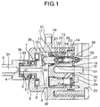
- Fig. 1 shows a longitudinal section of a pump of a first embodiment according to the present invention;
- Fig. 2 shows a structure of passages in a rear body of the first embodiment;
- Fig. 3 is an explanation figure of strokes;
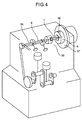
- Fig. 4 shows an engine oil passage of the first embodiment; and
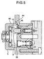
- Fig. 5 shows an oil passage of a second embodiment.
-
- A first embodiment is shown in Figs. 1-4.
- A
coupling 2 for transmitting a driving force transmitted by a cam shaft of an engine connects with ashaft 1 through apin 3. Theshaft 1 is integrated with aswash plate 9 which extends in the radial direction and has an end surface forming a slope. A slipper 10 contacts with theswash plate 9. Theslipper 10 is provided with a taper at its outer circumference portion in theswash plate 9 side for helping formation of an oil layer between theswash plate 9 and theslipper 10. Ahole 50 opening in the center of theslipper 10 connects theswash plate 9 side with the other side of theslipper 10 and forms a space for holding oil. Theswash plate 9 takes a role to supply oil scraped by theswash plate 9 from theswash plate 9 side to the other side of theslipper 10. Theslipper 10 has a spherical shape in the other side thereof and is supported by a sphere formed on aplunger 11 which slides in acylinder bore 13. The rotatingswash plate 9 causes a shaking movement which is converted to a reciprocating movement of theplunger 11. - In the pump having the above described structure, suction and discharge of fuel are performed as follows.
- A plurality of
pump chambers 14 are formed in acylinder block 12 by thecylinder bores 13 and theplungers 11. Anintake space 15 connected torespective plungers 11 is provided in the center of thecylinder block 12 to supply fuel to thepump chamber 14. In order to introduce fuel to theintake space 15, a fuel piping from the outside of the pump is connected to arear body 20 so as to connect with theintake space 15 provided in thecylinder block 12 thorough anintake passage 43 of therear body 20 and anintake chamber 30 in the center of therear body 20. - In the
plunger 11, an intake valve 24 (a check valve) is formed by aball 21, aspring 22, and astopper 23 supporting thespring 22. Aplunger spring 25 is installed to press always theplunger 11 toward theswash plate 9 side in order to allow theslipper 10 and theplunger 11 to follow theswash plate 9. - A connecting
passage A 16 toward anintake valve 24 in theplunger 11 is formed as the connecting passage between a spot facing 51 made in the cylinder bore and theintake space 15. The spot facing 51 has a diameter larger than that of thecylinder bore 13 and is formed up to a depth allowing the spot facing 51 to connect with an introducinghole 19 for always introducing fuel to the inside of theplunger 11 even if thepump chamber 14 becomes fully smaller (when the plunger position is at a top dead center). - Fig. 3 is an illustrated figure of strokes and an enlarged figure of the
plunger 11. In an intake stroke (a stroke in which theplunger 11 moving in a direction to increase a space of the pump chamber 14), theintake valve 24 installed in theplunger 11 is opened to introduce fuel into thepump chamber 14 when a pressure inside thepump chamber 14 installed in theplunger 11 reduces up to a pressure below a defined pressure. In this structure, when a discharge stroke (a stroke in which theplunger 11 moving in a direction to decrease the space of the pump chamber 14) has been started, fuel introduced into thepump chamber 14 during the intake stroke is sent out from thepump chamber 14 to adischarge chamber 29 installed in therear body 20 by opening adischarge valve 28 comprising aball 26 and aspring 27 at the time that a pressure of thepump chamber 14 comes to a defined pressure, as well as theintake valve 24. Anintake chamber 30 and thedischarge chamber 29 which are installed in therear body 20 are partitioned with an O-ring 31, and theintake chamber 30 is installed nearer the center than thedischarge chamber 29 so as to make the structure of the passage of the pump itself compact. - In the description stated before, a pressure of the
discharge chamber 29 can be regulated to an optimal pressure with a pressure regulating valve 40 (a pressure regulator: hereafter stated as P/Reg) installed in a passage connected to thedischarge chamber 29. The purpose for regulating the discharge pressure is to regulate an additional pressure applied to an injector (not illustrated) installed in the downstream of the discharge side. A high pressure fuel passed from a high pressure chamber of therear body 20 to P/Reg 40 is passed through aball valve 41 installed in P/Reg 40 and passed through connectingpassage B 42 installed in therear body 20 to return to theintake chamber 30. Anintake passage 43, theintake chamber 30, theintake space 15, and the connectingpassage A 16 form a passage for supplying fuel from a fuel source to respective cylinders. - As described above, a pressure inside the
pump chamber 14 also changes from a intake pressure (generally, from 0.2 MPa to 0.5 MPa) to a pressure of the high pressure chamber (generally, from 3 MPa to 20 Mpa). A load generated by a fuel pressure of the pump chamber is transmitted to theswash plate 9 of theshaft 1 via theplunger 14 and theslipper 10. This means that the resultant of force loads of a plurality of theplungers 11 acts on theswash plate 9. The resultant of forces acts as a radial load according to a load in the direction of the shaft and an angle of the swash plate. The present invention has the structure that theshaft 1 is engaged with a radial bearing 7 and the thrust bearing 8 to support its load by thebody 5 for supporting these loads and achieving a smoothed rotation. - Parts (slipper 10 /
swash plate surface 9, slipper 10 / plunger sphere, and bearing parts) supporting these loads are the parts supporting a relative speed and loads by rotation, and sliding wear can be reduced by oil lubrication. For this purpose, the structure is required to trap oil by aswash plate chamber 38 formed between thebody 5 and thecylinder 12. - In this embodiment, a shaft seal
A 17 for sealing fuel and oil during reciprocating movement of theplunger 11 is installed in thecylinder 12. This shaft sealA 17 seals a gap between theplunger 11 and the cylinder bore 13. The shaft sealA 17 seals fuel and oil. The present embodiment has a structure in which a pressure acting on theshaft seal A 17 is always the intake pressure of a low pressure to allow no application of a pressure of the high pressure chamber against theshaft seal A 17 because anintake passage 43 exists between theshaft seal A 17 and thepump chamber 14. By this reason, durability and reliability of theshaft seal 17 increase. - The following is an explanation of a circulation passage and a circulation method of oil. The structure of the example is that a
shaft 1 through which ashaft seal B 35 and acoupling 2 are penetrated is engaged with acoupling engaging part 33 of theengine cam 6 which is provided with anoil passage 34 in its shaft center, so that oil is introduced from an engine through a connectingpassage C 4 to theswash plate chamber 38 installed in the center of theshaft 1. Theshaft seal B 35 seals oil incompletely in a degree to allow necessary minimum flow from the engine side to aswash plate chamber 38. By this, an eccentric load on the driving shaft via theshaft seal B 35, which is caused by a distance of centers of theshaft 1 and theengine cam 6, can be suppressed in a maximum degree, so that durability of theradial bearing 7 is improved. In addition, since oil flowing into theswash plate chamber 38 is controlled as the necessarily minimized flow, rise of temperature of theswash plate chamber 38 is suppressed and oil diluted with fuel leaked to theswash plate chamber 38 from theshaft seal A 17 is replaced. Further, since the purpose is accomplished by introducing oil from the center of theshaft 1 without installation of a new oil passage in the engine side, fitness to the engine and miniaturization of the engine are accomplished. - In this embodiment, oil is introduced from a connecting
passage C 4 installed in the center of the shaft. Notwithstanding, the place is not restrictive if the passage for introducing oil is installed to connect the source of an oil pressure of the engine to theswash plate chamber 38 of the pump. - The following is a description of a passage to return oil, which is supplied from the engine to the
swash plate chamber 38, to the engine. This passage comprises areturn passage 36 from theswash plate chamber 38 to theengine cam chamber 39. Thereturn passage 36 is installed in acoupling 2 side of the surface of aflange 37 installed in thebody 5 of the pump to be attached to the engine. By this, oil in theswash plate chamber 38 can be returned to the engine without installing a special passage in the engine side. Thereturn passage 36 is installed in a level higher than a sliding surface between theswash plate 9 and theslipper 10. By this, if vapor occurs, the vapor is discharged from thereturn passage 36 to theengine cam chamber 39 to lubricate always the sliding surface with oil. The diameter of thereturn passage 36 is set larger than that of the connectingpassage C 4 for introducing oil. By this, the quantity of oil flowing out from theswash plate chamber 38 does not become lower than the quantity of oil flowing in, and the pressure of the inside of theswash plate chamber 38 does not rise, so that reliability of theshaft seal 17 is increased. - The pressure of the inside of the
swash plate chamber 38 does not rise to become always lower than an intake pressure of fuel. By this, leak of oil to the fuel side can be prevented. As well, theplunger 11 received always a force toward the swash plate so as to reduce a load on theplunger spring 25. The relations between pressures of respective parts are thus expressed by the following equation. - Intake fuel pressure ≧ oil chamber pressure;
and - oil pressure supplied from engine ≧ oil chamber pressure.
-
- Fig. 5 shows a second embodiment in which an
oil introducing passage 44 is installed to introduce oil positively from the engine. Theoil introducing passage 44 is installed in thebody 5 and aconstriction 45 is installed in the middle thereof. The pressure of oil-introducing side has been increased than that of theswash plate chamber 38. Installing theconstriction 45 suppresses an excessive oil flow with a high temperature to prevent heating of fuel. Besides, areturn passage 46 is installed in thebody 5 to return oil from theswash plate chamber 38 to theengine cam chamber 39. Thereturn passage 46 is installed in a level higher than a sliding surface between theswash plate 9 and theslipper 10. By this, if vapor occurs, the vapor is discharged from thereturn passage 46 to theengine cam chamber 39 to always lubricate the sliding surface with oil to increase reliability. - According to the features described above, the main body of the pump can be miniaturized since the pump requires no member such as bellows for insulating an oil circulating part from a fuel circulating part, and no sealing member installed at a part to which bellows is attached. Further, because the sliding part is lubricated with oil, a rolling bearing can be used as a bearing. Thus, a friction resistance is reduced, so that a driving torque can be decreased.
- Furthermore, because an existing oil passage of an engine can be used since an oil-introducing passage is installed on an axis of a cam shaft, no exclusive passage is required. Therefore, fitness to the engine is improved and also the miniaturization of the pump can be accomplished.
Claims (9)
- A high pressure fuel pump comprising:a cup-shaped body;a cylinder block engaged with the cup-shaped body so as to close the opening side of the cup-shaped body;a rotation shaft supported at the bottom of the cup-shaped body and rotated by a driving source;a swash plate disposed in a driving mechanism chamber inside the cup-shaped body, which converts a rotating movement to a shaking movement;a plunger reciprocated in a cylinder bore formed in the cylinder block according to the shaking movement of the swash plate;a sealing element provided between the inside wall of the cylinder bore and the plunger; andan oil supply mechanism which supplies oil to the driving mechanism chamber.
- A high pressure fuel pump comprising:a cup-shaped body;a cylinder block engaged with the cup-shaped body so as to close the opening side of the cup-shaped body;a rotation shaft supported at the bottom of the cup-shaped body and rotated by a driving source;a swash plate disposed in a driving mechanism chamber inside the cup-shaped body, which converts a rotating movement to a shaking movement;a plunger reciprocated in a cylinder bore formed in the cylinder block according to the shaking movement of the swash plate;a sealing element provided between the inside wall of the cylinder bore and the plunger;an oil supply mechanism which supplies oil to the driving mechanism chamber;a low pressure side fuel passage formed in the cylinder block; anda low pressure fuel introducing passage formed in the plunger, which connects the low pressure side fuel passage with a pump chamber formed in the cylinder bore, the pump chamber varying its capacity according to the plunger reciprocating in the cylinder bore.
- The high pressure fuel pump according to claim 2, further comprising:a valve mechanism disposed between the low pressure side fuel passage and the pump chamber, which shut off the connection between the low pressure side fuel passage and the pump chamber when a pressure of the pump chamber is more than a defined pressure, and
whereinthe sealing element is adopted to be acted by a pressure of the upper stream of the valve mechanism. - The high pressure fuel pump according to any one of claims 1-3, wherein an oil supply hole for supplying oil from the outside to the driving mechanism chamber is provided on at least one of the cup-shaped body and the rotation shaft.
- The high pressure fuel pump according to claim 1, wherein the oil supply mechanism connects the driving mechanism chamber with an oil tank of an engine and supplies engine oil to the driving mechanism chamber.
- The high pressure fuel pump according to claim 1 or 2, further comprising:a radial bearing attached to the cup-shaped body to support the rotation shaft; anda thrust rolling bearing provided on the back of the swash plate and having a roller or a ball with a longer rolling-pitch diameter than the outer diameter of the radial bearing for supporting an axial load generated by the plunger through the swash plate; and
whereinthe radial bearing and the thrust rolling bearing are disposed in the chamber. - The high pressure fuel pump according to claim 1 or 2, wherein the sealing element is a reciprocating sliding seal fixed to the cylinder block.
- The high pressure fuel pump according to claim 1, wherein the sealing element is a reciprocating sliding seal fixed to the plunger.
- A high pressure fuel pump comprising:a shaft for transmitting a driving force from the outside; a cam converting a rotating movement of the shaft to a reciprocating movement;a plunger reciprocated by the cam;a cylinder bore formed in a cylinder block;a pump chamber formed by putting the plunger into the cylinder bore;a sealing element sealing a space between the cylinder bore and the plunger; andan oil supply mechanism which supplies oil to the cam.
Applications Claiming Priority (2)
| Application Number | Priority Date | Filing Date | Title |
|---|---|---|---|
| JP17369599 | 1999-06-21 | ||
| JP11173695A JP2001003839A (en) | 1999-06-21 | 1999-06-21 | High pressure fuel pump |
Publications (2)
| Publication Number | Publication Date |
|---|---|
| EP1063428A2 true EP1063428A2 (en) | 2000-12-27 |
| EP1063428A3 EP1063428A3 (en) | 2001-10-31 |
Family
ID=15965410
Family Applications (1)
| Application Number | Title | Priority Date | Filing Date |
|---|---|---|---|
| EP00104550A Withdrawn EP1063428A3 (en) | 1999-06-21 | 2000-03-13 | High pressure fuel pump |
Country Status (3)
| Country | Link |
|---|---|
| US (2) | US6471491B1 (en) |
| EP (1) | EP1063428A3 (en) |
| JP (1) | JP2001003839A (en) |
Cited By (2)
| Publication number | Priority date | Publication date | Assignee | Title |
|---|---|---|---|---|
| DE10111837A1 (en) * | 2001-03-13 | 2002-09-26 | Bosch Gmbh Robert | Fuel metering system for an internal combustion engine with a high-pressure pump (HDP) module |
| CN106438258A (en) * | 2016-12-13 | 2017-02-22 | 荆门市召铭液压科技有限公司 | Disc type axial plunger pump with adjustable displacement |
Families Citing this family (9)
| Publication number | Priority date | Publication date | Assignee | Title |
|---|---|---|---|---|
| JP3924999B2 (en) * | 1999-08-12 | 2007-06-06 | 株式会社日立製作所 | Fuel pump and in-cylinder injection engine using the same |
| JP3787508B2 (en) | 2001-07-19 | 2006-06-21 | 株式会社日立製作所 | High pressure fuel supply pump |
| US20070009367A1 (en) * | 2005-04-21 | 2007-01-11 | Kmt Waterjet Systems, Inc. | Close fit cylinder and plunger |
| DE102008023990A1 (en) * | 2008-05-16 | 2009-11-19 | Rolls-Royce Deutschland Ltd & Co Kg | Two-shaft engine for an aircraft gas turbine |
| RU2478542C2 (en) * | 2008-07-08 | 2013-04-10 | Джапан Краун Корк Ко., Лтд. | Container lid made of synthetic resin |
| JP6091787B2 (en) | 2012-07-20 | 2017-03-08 | ヤンマー株式会社 | Fuel injection pump |
| US10184462B2 (en) * | 2015-11-06 | 2019-01-22 | Caterpillar Inc. | Drive assembly and pump assembly arrangement for cryogenic pump |
| CN106091010B (en) * | 2016-06-21 | 2019-03-08 | 中国航空工业集团公司沈阳发动机设计研究所 | A kind of engine chamber duplex burner valve |
| KR102290219B1 (en) * | 2019-11-25 | 2021-08-20 | 한국기계연구원 | High-pressure piston pump for spraying water fog |
Citations (2)
| Publication number | Priority date | Publication date | Assignee | Title |
|---|---|---|---|---|
| JPH09236080A (en) | 1996-02-29 | 1997-09-09 | Unisia Jecs Corp | Axial plunger pump |
| JPH09250447A (en) | 1996-03-15 | 1997-09-22 | Hitachi Ltd | Fluid supply pump and fuel supply pump |
Family Cites Families (17)
| Publication number | Priority date | Publication date | Assignee | Title |
|---|---|---|---|---|
| US3209701A (en) * | 1962-10-05 | 1965-10-05 | Sundstrand Corp | Pump |
| US3663122A (en) * | 1970-11-25 | 1972-05-16 | Mcneil Corp | Axial plunger pump |
| FR2204230A5 (en) * | 1972-10-20 | 1974-05-17 | Dowell Schlumberger | |
| US4046494A (en) * | 1975-08-20 | 1977-09-06 | Stanadyne, Inc. | Fuel injection pump and replaceable check valve therefor |
| US4197058A (en) * | 1978-07-26 | 1980-04-08 | Ford Motor Company | Fuel injection pump assembly |
| FR2454543A1 (en) * | 1979-04-19 | 1980-11-14 | Bronzavia Sa | MACHINE, SUCH AS A PUMP, OF WHICH AT LEAST CERTAIN MOBILE PARTS ARE IN CONTACT WITH SEA WATER |
| US4531494A (en) * | 1984-03-27 | 1985-07-30 | Caterpillar Tractor Co. | Distributor fuel injection pump having a nutator pump subassembly |
| DE3440850A1 (en) * | 1984-11-08 | 1986-05-22 | Mannesmann Rexroth GmbH, 8770 Lohr | AXIAL PISTON PUMP |
| JPH061782U (en) * | 1992-06-08 | 1994-01-14 | 株式会社豊田自動織機製作所 | Variable capacity swash plate compressor |
| US5647266A (en) * | 1994-10-03 | 1997-07-15 | Dynex/Rivett, Inc. | Hold-down mechanism for hydraulic pump |
| JP3651044B2 (en) * | 1995-02-24 | 2005-05-25 | 日産自動車株式会社 | Bellows pump |
| JPH09112408A (en) * | 1995-10-19 | 1997-05-02 | Hitachi Ltd | Fuel pump |
| DE19708917B4 (en) * | 1996-03-13 | 2006-05-24 | Volkswagen Ag | Axial piston pump for conveying a fluid |
| US6179574B1 (en) * | 1997-01-22 | 2001-01-30 | Jetec Company | Apparatus for pressurizing fluids and using them to perform work |
| JPH10318123A (en) * | 1997-05-19 | 1998-12-02 | Honda Motor Co Ltd | High pressure fuel pump |
| JPH1172014A (en) * | 1997-06-24 | 1999-03-16 | Unisia Jecs Corp | Fuel pressurization pump |
| JP2000110710A (en) * | 1998-10-08 | 2000-04-18 | Hitachi Ltd | High pressure fuel pump |
-
1999
- 1999-06-21 JP JP11173695A patent/JP2001003839A/en active Pending
-
2000
- 2000-03-13 EP EP00104550A patent/EP1063428A3/en not_active Withdrawn
- 2000-03-16 US US09/526,742 patent/US6471491B1/en not_active Expired - Fee Related
-
2002
- 2002-05-09 US US10/141,119 patent/US6488478B2/en not_active Expired - Fee Related
Patent Citations (2)
| Publication number | Priority date | Publication date | Assignee | Title |
|---|---|---|---|---|
| JPH09236080A (en) | 1996-02-29 | 1997-09-09 | Unisia Jecs Corp | Axial plunger pump |
| JPH09250447A (en) | 1996-03-15 | 1997-09-22 | Hitachi Ltd | Fluid supply pump and fuel supply pump |
Cited By (3)
| Publication number | Priority date | Publication date | Assignee | Title |
|---|---|---|---|---|
| DE10111837A1 (en) * | 2001-03-13 | 2002-09-26 | Bosch Gmbh Robert | Fuel metering system for an internal combustion engine with a high-pressure pump (HDP) module |
| DE10111837B4 (en) * | 2001-03-13 | 2005-09-29 | Robert Bosch Gmbh | Fuel metering system for an internal combustion engine with a high-pressure pump (HDP) module |
| CN106438258A (en) * | 2016-12-13 | 2017-02-22 | 荆门市召铭液压科技有限公司 | Disc type axial plunger pump with adjustable displacement |
Also Published As
| Publication number | Publication date |
|---|---|
| US20020127119A1 (en) | 2002-09-12 |
| US6488478B2 (en) | 2002-12-03 |
| US6471491B1 (en) | 2002-10-29 |
| EP1063428A3 (en) | 2001-10-31 |
| JP2001003839A (en) | 2001-01-09 |
Similar Documents
| Publication | Publication Date | Title |
|---|---|---|
| US6471491B1 (en) | High pressure fuel pump | |
| KR101559335B1 (en) | Improvements to fuel pumps | |
| US7794216B2 (en) | High-pressure pump | |
| JPH10227278A (en) | Piston pump | |
| US6210127B1 (en) | Fuel pump | |
| US5782161A (en) | Axial plunger pump with a partition between the lubricating chamber and the working fluid chamber | |
| JP2001221131A (en) | Mechanism for lubricating tappet for fuel injection pump | |
| JPH0868370A (en) | High pressure fuel feed pump | |
| US7024980B2 (en) | High-pressure fuel pump | |
| US6368071B1 (en) | High pressure fuel pump | |
| EP1344932B1 (en) | Lubricant supply unit of high pressure fuel pump | |
| US6796775B2 (en) | Fuel injection pump | |
| US6622706B2 (en) | Pump, pump components and method | |
| US6261069B1 (en) | Shaft seal with pressure equalizing shuttle | |
| US6893228B2 (en) | Axial piston pump with fluid bearing arrangement | |
| KR20170044754A (en) | High-pressure fuel pump, in particular for a fuel injection device of an internal combustion engine | |
| JP2003049743A (en) | Fuel pump for fuel system of internal combustion engine | |
| US4242063A (en) | High pressure multi-cylinder pump | |
| JP2001280220A (en) | High pressure fuel pump | |
| JP2000009025A (en) | Plunger assembly for axial plunger type hydraulic equipment | |
| US5216993A (en) | Fuel injection pump for internal combustion engines | |
| JP2008163829A (en) | Fuel injection pump | |
| JP4542294B2 (en) | Improved high pressure pump | |
| JPH11351096A (en) | Fuel pump | |
| JP2000045907A (en) | Fuel pump |
Legal Events
| Date | Code | Title | Description |
|---|---|---|---|
| PUAI | Public reference made under article 153(3) epc to a published international application that has entered the european phase |
Free format text: ORIGINAL CODE: 0009012 |
|
| AK | Designated contracting states |
Kind code of ref document: A2 Designated state(s): DE FR GB IT Kind code of ref document: A2 Designated state(s): AT BE CH CY DE DK ES FI FR GB GR IE IT LI LU MC NL PT SE |
|
| AX | Request for extension of the european patent |
Free format text: AL;LT;LV;MK;RO;SI |
|
| PUAL | Search report despatched |
Free format text: ORIGINAL CODE: 0009013 |
|
| AK | Designated contracting states |
Kind code of ref document: A3 Designated state(s): AT BE CH CY DE DK ES FI FR GB GR IE IT LI LU MC NL PT SE |
|
| AX | Request for extension of the european patent |
Free format text: AL;LT;LV;MK;RO;SI |
|
| RIC1 | Information provided on ipc code assigned before grant |
Free format text: 7F 04B 1/20 A, 7F 04B 1/14 B, 7F 04B 1/12 B, 7F 04B 53/16 B |
|
| 17P | Request for examination filed |
Effective date: 20020304 |
|
| AKX | Designation fees paid |
Free format text: DE FR GB IT |
|
| 17Q | First examination report despatched |
Effective date: 20031103 |
|
| STAA | Information on the status of an ep patent application or granted ep patent |
Free format text: STATUS: THE APPLICATION IS DEEMED TO BE WITHDRAWN |
|
| 18D | Application deemed to be withdrawn |
Effective date: 20040316 |