EP1063188A2 - Vacuum conveyor - Google Patents
Vacuum conveyor Download PDFInfo
- Publication number
- EP1063188A2 EP1063188A2 EP00110076A EP00110076A EP1063188A2 EP 1063188 A2 EP1063188 A2 EP 1063188A2 EP 00110076 A EP00110076 A EP 00110076A EP 00110076 A EP00110076 A EP 00110076A EP 1063188 A2 EP1063188 A2 EP 1063188A2
- Authority
- EP
- European Patent Office
- Prior art keywords
- vacuum
- conveyor
- belt
- conveyor belt
- suction box
- Prior art date
- Legal status (The legal status is an assumption and is not a legal conclusion. Google has not performed a legal analysis and makes no representation as to the accuracy of the status listed.)
- Withdrawn
Links
Images


Classifications
-
- D—TEXTILES; PAPER
- D21—PAPER-MAKING; PRODUCTION OF CELLULOSE
- D21G—CALENDERS; ACCESSORIES FOR PAPER-MAKING MACHINES
- D21G9/00—Other accessories for paper-making machines
- D21G9/0063—Devices for threading a web tail through a paper-making machine
-
- B—PERFORMING OPERATIONS; TRANSPORTING
- B65—CONVEYING; PACKING; STORING; HANDLING THIN OR FILAMENTARY MATERIAL
- B65G—TRANSPORT OR STORAGE DEVICES, e.g. CONVEYORS FOR LOADING OR TIPPING, SHOP CONVEYOR SYSTEMS OR PNEUMATIC TUBE CONVEYORS
- B65G21/00—Supporting or protective framework or housings for endless load-carriers or traction elements of belt or chain conveyors
- B65G21/20—Means incorporated in, or attached to, framework or housings for guiding load-carriers, traction elements or loads supported on moving surfaces
- B65G21/2027—Suction retaining means
- B65G21/2036—Suction retaining means for retaining the load on the load-carrying surface
-
- B—PERFORMING OPERATIONS; TRANSPORTING
- B65—CONVEYING; PACKING; STORING; HANDLING THIN OR FILAMENTARY MATERIAL
- B65H—HANDLING THIN OR FILAMENTARY MATERIAL, e.g. SHEETS, WEBS, CABLES
- B65H5/00—Feeding articles separated from piles; Feeding articles to machines
- B65H5/22—Feeding articles separated from piles; Feeding articles to machines by air-blast or suction device
- B65H5/222—Feeding articles separated from piles; Feeding articles to machines by air-blast or suction device by suction devices
- B65H5/224—Feeding articles separated from piles; Feeding articles to machines by air-blast or suction device by suction devices by suction belts
Definitions
- the invention relates to a vacuum conveyor with the characteristics stated in the preamble of claim 1.
- a vacuum conveyor is known from DE 26 36 887 (File PD 10778). Conveyors of this kind have proven successful in operation. In many applications, however, a disturbing factor is that with the known conveyor the connection for the vacuum pipe is arranged at one of the side walls of the suction box. Such an arrangement of the vacuum connection seems suitable because only the two side walls of the suction box are free outwards, i.e. are accessible directly from outside. In most cases the two pulleys over which the endless conveyor belt runs, and the suction box located in between, fill the interior space of the endless conveyor belt almost completely.
- the invention is based on the problem of further developing the known vacuum conveyor in such a way that as many of the stated demands as possible are met.
- a further advantage of the solution in accordance with the invention consists in that the air flow through the suction box and through the vacuum connection is without any deflection to the side. This makes it possible for the air flow to remove any existing dirt particles from the conveyor more reliably than in the past. In particular, the tendency for dirt to collect inside the suction box is reduced. The pores of the conveyor belt are kept free from dust deposits in a better way than before. All in all, a continuous self-cleaning effect is achieved.
- a further characteristic feature of the vacuum conveyor of the invention is the novel type of supporting means which connects the suction box with the suction nozzle mentioned in claim 2. It should be noted that - according to the invention - the supporting means grips around the edges of the return run of the belt (claim 3).
- sealing elements may be used at the exhaust opening of the suction box and/or around the air flow path going through the supporting means (claim 4).
- the suction nozzle without the suction pipe or together with the suction pipe, should perform a double function. It is used both to exhaust the air and also to carry the conveyor, i.e. to fasten the conveyor to a machine frame, rack or similar structure.
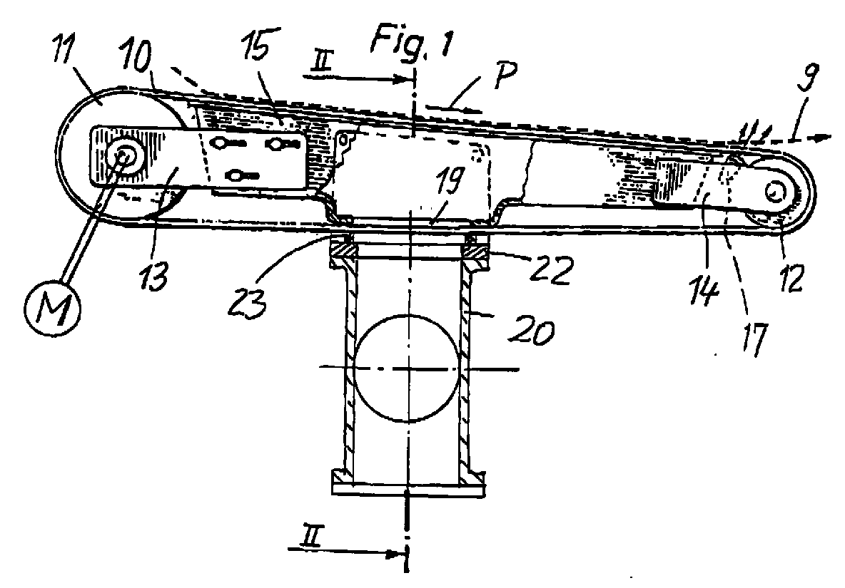
- the vacuum conveyor shown in FIGURES 1 and 2 is used to guide a running web, in particular a threading tail 9.
- a running web e.g. of a paper or board web
- threading tail 9 is, as is known, part of a running web, e.g. of a paper or board web, and is used for the threading" of the web, e.g. inside a papermaking machine.
- the conveyor includes an air-pervious, endless conveyor belt 10, which runs over two pulleys 11, 12 and over a suction box 15.
- the two pulleys 11, 12 are rotatably mounted in holders 13, 14, which are fastened to the suction box 15.
- One of the pulleys (11) is provided with a drive, which is shown only diagrammatically in FIGURE 1.
- Suction box 15 has a cover plate 16 provided with slots (or similar openings). Sliding on this plate is the conveying run of the air-pervious conveyor belt 10; due to this, web 9 is sucked onto the conveyor belt and transported.
- an air blow nozzle 17 can be provided at the end of the conveyor.
- suction box 15 to a source of vacuum 18; in the area of the return run (in the present case of the lower run) suction box 15 has a relatively large exhaust opening 19 or, for example, a large number of exhaust slots.
- the return run of the conveyor belt 10 slides over this part of the suction box 15 (or over sealing strips fitted there, not shown).
- a suction nozzle 20 open towards exhaust opening 19. This is connected to the source of vacuum 18 via a vacuum pipe 21. The vacuum therefore propagates over the suction nozzle 20 and through the return run of the conveyor belt to the interior of the suction box 15.
- suction nozzle 20 and suction box 15 there are several possibilities of rigidly connecting suction nozzle 20 and suction box 15 to each other.
- Conceivable are, for example, several supporting pins, which are anchored on the side walls of suction box 15 and on suction nozzle 20.
- sealing strips are arranged at suction nozzle 20, over which conveyor belt 10 slides.
- Preference is, however, given to the illustrated type of construction with a U-shaped supporting means 22, which grips around the edges of the return run of the conveyor belt 10.
- the legs of the supporting means 22 projecting (in the present case) upwards are screwed to the side walls of suction box 15.
- the base of the U-shaped supporting means 22 has a large-area suction opening.
- supporting means 22 is connected to suction nozzle 20 and carries sealing elements, e.g.
- U-shaped supporting means 22 By means of these U-shaped supporting means 22 a very rigid connection is created between suction nozzle 20 and suction box 15. This makes it possible for suction nozzle 20 to carry the entire vacuum conveyor, so that the otherwise customary supporting means can be omitted.
- a horizontal supporting arm 24 is fastened to or moulded on suction nozzle 20, whose free end is clamped into a machine frame 25.
- Pipe 21 leading to the source of vacuum 18 can be connected directly underneath exhaust opening 19 to suction nozzle 20, There is, however, also a possibility (shown in dot-dash-lines) of connecting the vacuum source 18' via pipe 21' (e.g. at a flange 26) to supporting arm 24, if this is designed as a hollow carrier open to suction nozzle 20.
- FIGURE 3 shows again an endless belt 10, two pulleys 11, 12 (of equal size), holders 13A and 13B and a suction box 15A with cover plate 16.
- a supporting means 22A which connects the suction box 15A with suction nozzle 20A comprises a plate 22a and two side walls 22c. Plate 22a is parallel to belt 10 and has an exhaust opening 22b.
- Connected to supporting means 22A is a base plate 22d for an electric motor M driving pulley 11.
- the small gap between the bottom of suction box 15A and the inner side of the return run of belt 10 may be free of sealing elements.
- the only sealing elements 23A are two rotatable cylindrical rolls extending across the belt travel direction. They may be arranged as to contact the outside of belt 10 but to avoid contact to plate 22a.
Landscapes
- Engineering & Computer Science (AREA)
- Mechanical Engineering (AREA)
- Advancing Webs (AREA)
- Delivering By Means Of Belts And Rollers (AREA)
- Structure Of Belt Conveyors (AREA)
- Paper (AREA)
Abstract
Description
- FIGURE 1
- shows a vacuum conveyor partly in side view elevation, partly in cross-section;
- FIGURE 2
- shows a cross-section along line II-II of FIGURE 1;
- FIGURE 3
- shows a further improved vacuum conveyor partly in a side view partly in a longitudinal section;
- FIGURE 4
- is a cross-section along line IV of Figure 3.

Claims (12)
- Vacuum conveyor, which is suitable for guiding a running web (9), e.g. paper web, in particular a threading tail (e.g. duringthreading" of a paper or board web into a machine for the production or finishing or processing of such a web), with the following characteristics:
 a) an air-pervious endless conveyor belt (10) is tensioned over two pulleys (11, 12) and comprises a conveying run and a return run;b) in the loop of the conveyor belt (10) is located (apart from the said pulleys) a suction box (15) that is connected via an air flow path to a source of vacuum (18);c) at least one of the pulleys can be driven, to allow the endless conveyor belt (10) to travel over the pulleys (11, 12) and over the suction box (15), whereby the vacuum propagates through the conveying run of the conveyor belt running in the direction of web travel, in order to draw the web to be guided onto the conveyor belt by suction;d) characterized in that the air flow path (19, 20), from the suction box (15) to the source of vacuum (18), runs through the return run of the conveyor belt (10).
 - Vacuum conveyor as claimed in claim 1, characterized by the following features:a) the suction box (15) has at least one exhaust opening (19) open towards the return run of the conveyor belt;b) provided outside of the loop of the conveyor belt (10) is a suction nozzle (20) open to the said exhaust opening (19), a vacuum pipe (21) being connected to the suction nozzle.
- Vacuum conveyor as claimed in claim 2, characterized in that suction nozzle (20) and suction box (15) are rigidly connected to each other, with the help of a supporting means (22), which grips around the edges of the return run of the conveyor belt (10).
- Vacuum conveyor as claimed in claim 2 or 3, characterized in that at the exhaust opening (19) of the suction box (15) and/or at the suction nozzle (20) and/or at the supporting means (22) sealing elements (23) are provided, over which the conveyor belt (10) slides.
- Vacuum conveyor as claimed in claim 4 characterized by the following features:a) the supporting means (22A) comprises a plate (22a) extending parallell to the outside of the return run of belt (10) and having an exhaust opening (22b) which at least approximately coincides with the exhaust opening (19) of suction box (15);b) the supporting means (22A) also comprises a sealing means (23A) arranged between the plate (22a) and the return run of belt (10).
- Vacuum conveyor as claimed in claim 5, wherein a gap is formed between the suction box (15) and the inner side of the return run of belt (10), characterized in that said gap is free of any sealing means.
- Vacuum conveyor as claimed in claim 5 or 6 characterized by the following features:a) the sealing means (23A) comprises two rotatable sealing elements, each being formed as a cylindrical roll;b) said sealing elements extend across the travelling direction of the return run of belt (10);c) referring to the travel direction of the return run of belt (10), one of said sealing elements is arranged in front of the exhaust opening of the supporting means (22A), while the other of said sealing elements is behind said exhaust opening.
- Vacuum conveyor as claimed in claim 7, characterized in that the rotatable sealing elements are arranged in a position which allows a contact of the sealing elements with the outside of the return run of the belt (10) and which avoids a contact between the sealing elements and the plate (22a).
- Vacuum conveyor as claimed in claim 7 or claim 8, characterized in that the two rotating sealing elements are the only sealing means present in the area of the air-flow path from the suction box (15) to the suction nozzle (20).
- Vacuum conveyor as claimed in claim 3, characterized in that the supporting means (22A) comprises a support (22d) for a drive (M) driving one of said pulleys.
- Vacuum conveyor as claimed in one of claims 2 to 4, characterized in that the suction nozzle (20) is designed as part of an assembly (20, 24, 25) supporting the entire vacuum conveyor.
- Vacuum conveyor as claimed in claim 11, characterized in that also a part (24) of the vacuum piping, which connects the suction nozzle (20) to the source of vacuum (18), is an integral part of the assembly (20, 24, 25) carrying the vacuum conveyor.
Applications Claiming Priority (2)
| Application Number | Priority Date | Filing Date | Title |
|---|---|---|---|
| DE29910850U | 1999-06-25 | ||
| DE29910850U DE29910850U1 (en) | 1999-06-25 | 1999-06-25 | Vacuum conveyor |
Publications (2)
| Publication Number | Publication Date |
|---|---|
| EP1063188A2 true EP1063188A2 (en) | 2000-12-27 |
| EP1063188A3 EP1063188A3 (en) | 2002-02-27 |
Family
ID=8075116
Family Applications (1)
| Application Number | Title | Priority Date | Filing Date |
|---|---|---|---|
| EP00110076A Withdrawn EP1063188A3 (en) | 1999-06-25 | 2000-05-12 | Vacuum conveyor |
Country Status (5)
| Country | Link |
|---|---|
| US (2) | US6405914B1 (en) |
| EP (1) | EP1063188A3 (en) |
| JP (1) | JP2001048385A (en) |
| CA (1) | CA2312555A1 (en) |
| DE (1) | DE29910850U1 (en) |
Cited By (4)
| Publication number | Priority date | Publication date | Assignee | Title |
|---|---|---|---|---|
| US7500553B2 (en) | 2004-03-11 | 2009-03-10 | Metso Paper, Inc. | Belt conveyor for transferring a web threading tail in a web manufacturing machine and a method for changing the belt loop of a belt conveyor for a web threading tail in a web manufacturing machine |
| EP1792860A3 (en) * | 2005-11-30 | 2009-03-11 | Andritz Küsters GmbH | Vacuum web transport device for guiding a running web |
| US7510069B2 (en) | 2004-03-11 | 2009-03-31 | Metso Paper, Inc. | Vacuum belt conveyor for transferring a web threading tail in a web manufacturing machine |
| WO2012041727A1 (en) * | 2010-09-27 | 2012-04-05 | Oce-Technologies B.V. | Sheet conveying device |
Families Citing this family (11)
| Publication number | Priority date | Publication date | Assignee | Title |
|---|---|---|---|---|
| DE19755058C1 (en) * | 1997-12-11 | 1999-08-12 | Lohmann Therapie Syst Lts | Device with suction openings for transferring flat products to a conveyor belt |
| DE20019346U1 (en) | 2000-11-14 | 2001-02-22 | Voith Paper Patent GmbH, 89522 Heidenheim | Vacuum belt conveyor |
| FI116664B (en) | 2004-06-18 | 2006-01-31 | Metso Paper Inc | Method and apparatus of a paper or cardboard machine |
| DE102007024945A1 (en) * | 2006-06-06 | 2007-12-13 | Eastman Kodak Co. | Sheet transporting method for use in e.g. inkjet printer, involves applying electrical charges in area within which sheet is sucked into rotating conveyor for generating electrostatic retention force between rotating conveyor and sheet |
| DE102007041811A1 (en) * | 2007-09-03 | 2009-03-05 | Böwe Systec AG | Apparatus and method for conveying a paper web |
| US8398063B2 (en) * | 2008-12-10 | 2013-03-19 | Gross International Americas, Inc. | Ribbon transport apparatus and method |
| US8388246B2 (en) * | 2009-09-15 | 2013-03-05 | Xerox Corporation | Web driven vacuum transport |
| JP6199790B2 (en) * | 2014-04-10 | 2017-09-20 | 京セラドキュメントソリューションズ株式会社 | Conveying apparatus and inkjet recording apparatus |
| US11071254B2 (en) * | 2016-07-19 | 2021-07-27 | Deere & Company | System and method for directing a module wrap |
| WO2019118579A2 (en) * | 2017-12-13 | 2019-06-20 | Laitram, L.L.C. | Hygienic hollow frame assembly |
| CN119568795B (en) * | 2024-12-17 | 2025-12-19 | 太仓市岭南纸业包装有限公司 | A corrugated cardboard feeding device based on an adjustable ring belt mechanism |
Family Cites Families (16)
| Publication number | Priority date | Publication date | Assignee | Title |
|---|---|---|---|---|
| DE1075932B (en) * | 1958-07-01 | 1960-02-18 | Goebel Gmbh Maschf | Device for intermittent conveying of webs of paper, cardboard or the like. |
| US3425610A (en) * | 1966-06-29 | 1969-02-04 | Koppers Co Inc | Vacuum device for advancing a continuous web |
| GB1533720A (en) * | 1975-08-18 | 1978-11-29 | Rooney S | Transfer apparatus for paper making machines |
| US4022366A (en) | 1976-03-22 | 1977-05-10 | Durad Machine Company Ltd. | Sheet handling apparatus |
| JPS52159473U (en) * | 1976-05-28 | 1977-12-03 | ||
| IT1119879B (en) * | 1979-10-08 | 1986-03-10 | Gd Spa | TAPE GUIDE DEVICE PARTICULARLY FOR CIGARETTE PACKAGING MACHINES |
| US4295737A (en) * | 1980-01-10 | 1981-10-20 | Xerox Corporation | Grooved belt document registration system |
| US4298277A (en) * | 1980-01-10 | 1981-11-03 | Xerox Corporation | Grooved vacuum belt document handling system |
| JPS57182423A (en) * | 1981-05-08 | 1982-11-10 | Mitsubishi Heavy Ind Ltd | Pasting device |
| IT1184341B (en) * | 1984-03-29 | 1987-10-28 | Hauni Werke Koerber & Co Kg | DEVICE FOR FEEDING WRAPPING LINING MATERIAL TO A PACKAGING MACHINE, ESPECIALLY CIGARETTES PACKAGING MACHINE |
| US4660752A (en) * | 1985-08-29 | 1987-04-28 | Compak/Webcor Manufacturing Packaging Co. | Vacuum feeder for continuous web |
| DE3919291C2 (en) * | 1988-06-14 | 1995-07-06 | Tokyo Kikai Seisakusho Ltd | Path feed roller and drive control arrangement therefor |
| JP2505273Y2 (en) | 1990-01-26 | 1996-07-24 | 池上通信機株式会社 | Object transport device |
| DE4416289C2 (en) * | 1994-05-07 | 2003-06-05 | Heidelberger Druckmasch Ag | Device for conveying a shingled stream of sheets |
| DE4416286C2 (en) * | 1994-05-07 | 1999-10-28 | Heidelberger Druckmasch Ag | Device for adjusting the negative pressure in a suction belt feed table of a sheet feeder |
| US5878868A (en) * | 1996-05-06 | 1999-03-09 | Ikegami Tsushinki Co., Ltd. | Object inspection apparatus |
-
1999
- 1999-06-25 DE DE29910850U patent/DE29910850U1/en not_active Expired - Lifetime
-
2000
- 2000-05-12 EP EP00110076A patent/EP1063188A3/en not_active Withdrawn
- 2000-06-23 US US09/599,538 patent/US6405914B1/en not_active Expired - Fee Related
- 2000-06-23 JP JP2000190117A patent/JP2001048385A/en active Pending
- 2000-06-23 CA CA002312555A patent/CA2312555A1/en not_active Abandoned
-
2002
- 2002-02-14 US US10/073,980 patent/US20020074377A1/en not_active Abandoned
Cited By (7)
| Publication number | Priority date | Publication date | Assignee | Title |
|---|---|---|---|---|
| US7500553B2 (en) | 2004-03-11 | 2009-03-10 | Metso Paper, Inc. | Belt conveyor for transferring a web threading tail in a web manufacturing machine and a method for changing the belt loop of a belt conveyor for a web threading tail in a web manufacturing machine |
| US7510069B2 (en) | 2004-03-11 | 2009-03-31 | Metso Paper, Inc. | Vacuum belt conveyor for transferring a web threading tail in a web manufacturing machine |
| EP1792860A3 (en) * | 2005-11-30 | 2009-03-11 | Andritz Küsters GmbH | Vacuum web transport device for guiding a running web |
| WO2012041727A1 (en) * | 2010-09-27 | 2012-04-05 | Oce-Technologies B.V. | Sheet conveying device |
| WO2012041726A1 (en) * | 2010-09-27 | 2012-04-05 | Oce-Technologies B.V. | Printing system with sheet conveying device |
| US8702098B2 (en) | 2010-09-27 | 2014-04-22 | Oce-Technologies B.V. | Printing system with sheet conveying device |
| US9051138B2 (en) | 2010-09-27 | 2015-06-09 | Oce-Technologies B.V. | Sheet conveying device |
Also Published As
| Publication number | Publication date |
|---|---|
| US20020074377A1 (en) | 2002-06-20 |
| JP2001048385A (en) | 2001-02-20 |
| DE29910850U1 (en) | 2000-11-23 |
| CA2312555A1 (en) | 2000-12-25 |
| US6405914B1 (en) | 2002-06-18 |
| EP1063188A3 (en) | 2002-02-27 |
Similar Documents
| Publication | Publication Date | Title |
|---|---|---|
| US6405914B1 (en) | Vacuum conveyor | |
| US5443005A (en) | Dusting device | |
| CA1237452A (en) | Device to pick up sheets from a stack and transport the sheets away from the stack | |
| EP1127978B1 (en) | Vacuum belt conveyor | |
| US6648198B2 (en) | Vacuum belt conveyor | |
| DE60007489D1 (en) | Device for transporting a material web | |
| FI94652C (en) | Device for holding the side edge of a web in accordance with a dryer blanket of a paper machine | |
| EP1021618B1 (en) | Device for conveying and guiding a lead-in strip of a web in a paper machine | |
| JP2981388B2 (en) | How to fix paper insertion plate and suction belt | |
| JP2001020172A (en) | Sucking device for textile machine, especially water flow ject interlacing device | |
| JPH10180016A (en) | Continuous treatment type apparatus for separation of solid from liquid | |
| CS9001002A2 (en) | Sheet delivery | |
| US5531313A (en) | Device for conveying a continuous shingled sheet stream | |
| JP2022047243A (en) | Supply device of sheet-like medium and use device | |
| EP0987107A2 (en) | Sheet-like material guiding device of offset printing press | |
| CN1009942B (en) | Device for removing fibre material by suction | |
| US6758027B2 (en) | Envelope-filling bench | |
| JPH1159849A (en) | Air levitated belt conveyor | |
| US1211739A (en) | Suction-box. | |
| US6059093A (en) | Device for transporting printed sheets | |
| US20020171196A1 (en) | Transport device for flat goods, especially paper | |
| JP7718102B2 (en) | Sheet media supply and use device | |
| JPH10316244A (en) | Trough connection structure of air-floating rollerless belt conveyor | |
| CN118183165B (en) | A chain splitter for high-ventilation mesh belt machines | |
| US11753251B1 (en) | Conveyor end drive with weighted take-up roller |
Legal Events
| Date | Code | Title | Description |
|---|---|---|---|
| PUAI | Public reference made under article 153(3) epc to a published international application that has entered the european phase |
Free format text: ORIGINAL CODE: 0009012 |
|
| AK | Designated contracting states |
Kind code of ref document: A2 Designated state(s): AT BE CH CY DE DK ES FI FR GB GR IE IT LI LU MC NL PT SE |
|
| AX | Request for extension of the european patent |
Free format text: AL;LT;LV;MK;RO;SI |
|
| PUAL | Search report despatched |
Free format text: ORIGINAL CODE: 0009013 |
|
| RIC1 | Information provided on ipc code assigned before grant |
Free format text: 7B 65H 19/29 A, 7B 65H 5/22 B, 7D 21G 9/00 B, 7B 65G 21/20 B |
|
| AK | Designated contracting states |
Kind code of ref document: A3 Designated state(s): AT BE CH CY DE DK ES FI FR GB GR IE IT LI LU MC NL PT SE |
|
| AX | Request for extension of the european patent |
Free format text: AL;LT;LV;MK;RO;SI |
|
| AKX | Designation fees paid | ||
| REG | Reference to a national code |
Ref country code: DE Ref legal event code: 8566 |
|
| STAA | Information on the status of an ep patent application or granted ep patent |
Free format text: STATUS: THE APPLICATION IS DEEMED TO BE WITHDRAWN |
|
| 18D | Application deemed to be withdrawn |
Effective date: 20020828 |