EP1062491B1 - Method and apparatus for conveying a sample to a sample vessel - Google Patents
Method and apparatus for conveying a sample to a sample vessel Download PDFInfo
- Publication number
- EP1062491B1 EP1062491B1 EP99963604A EP99963604A EP1062491B1 EP 1062491 B1 EP1062491 B1 EP 1062491B1 EP 99963604 A EP99963604 A EP 99963604A EP 99963604 A EP99963604 A EP 99963604A EP 1062491 B1 EP1062491 B1 EP 1062491B1
- Authority
- EP
- European Patent Office
- Prior art keywords
- rack
- tooth
- sample
- sample disk
- teeth
- Prior art date
- Legal status (The legal status is an assumption and is not a legal conclusion. Google has not performed a legal analysis and makes no representation as to the accuracy of the status listed.)
- Expired - Lifetime
Links
Images

Classifications
-
- B—PERFORMING OPERATIONS; TRANSPORTING
- B01—PHYSICAL OR CHEMICAL PROCESSES OR APPARATUS IN GENERAL
- B01L—CHEMICAL OR PHYSICAL LABORATORY APPARATUS FOR GENERAL USE
- B01L3/00—Containers or dishes for laboratory use, e.g. laboratory glassware; Droppers
- B01L3/56—Labware specially adapted for transferring fluids
- B01L3/563—Joints or fittings; Separable fluid transfer means to transfer fluids between at least two containers, e.g. connectors
-
- G—PHYSICS
- G01—MEASURING; TESTING
- G01N—INVESTIGATING OR ANALYSING MATERIALS BY DETERMINING THEIR CHEMICAL OR PHYSICAL PROPERTIES
- G01N35/00—Automatic analysis not limited to methods or materials provided for in any single one of groups G01N1/00 - G01N33/00; Handling materials therefor
- G01N35/02—Automatic analysis not limited to methods or materials provided for in any single one of groups G01N1/00 - G01N33/00; Handling materials therefor using a plurality of sample containers moved by a conveyor system past one or more treatment or analysis stations
- G01N35/028—Automatic analysis not limited to methods or materials provided for in any single one of groups G01N1/00 - G01N33/00; Handling materials therefor using a plurality of sample containers moved by a conveyor system past one or more treatment or analysis stations having reaction cells in the form of microtitration plates
-
- G—PHYSICS
- G01—MEASURING; TESTING
- G01N—INVESTIGATING OR ANALYSING MATERIALS BY DETERMINING THEIR CHEMICAL OR PHYSICAL PROPERTIES
- G01N35/00—Automatic analysis not limited to methods or materials provided for in any single one of groups G01N1/00 - G01N33/00; Handling materials therefor
- G01N35/02—Automatic analysis not limited to methods or materials provided for in any single one of groups G01N1/00 - G01N33/00; Handling materials therefor using a plurality of sample containers moved by a conveyor system past one or more treatment or analysis stations
- G01N35/04—Details of the conveyor system
-
- G—PHYSICS
- G01—MEASURING; TESTING
- G01N—INVESTIGATING OR ANALYSING MATERIALS BY DETERMINING THEIR CHEMICAL OR PHYSICAL PROPERTIES
- G01N1/00—Sampling; Preparing specimens for investigation
- G01N1/28—Preparing specimens for investigation including physical details of (bio-)chemical methods covered elsewhere, e.g. G01N33/50, C12Q
- G01N1/286—Preparing specimens for investigation including physical details of (bio-)chemical methods covered elsewhere, e.g. G01N33/50, C12Q involving mechanical work, e.g. chopping, disintegrating, compacting, homogenising
- G01N2001/2873—Cutting or cleaving
- G01N2001/288—Filter punches
-
- Y—GENERAL TAGGING OF NEW TECHNOLOGICAL DEVELOPMENTS; GENERAL TAGGING OF CROSS-SECTIONAL TECHNOLOGIES SPANNING OVER SEVERAL SECTIONS OF THE IPC; TECHNICAL SUBJECTS COVERED BY FORMER USPC CROSS-REFERENCE ART COLLECTIONS [XRACs] AND DIGESTS
- Y10—TECHNICAL SUBJECTS COVERED BY FORMER USPC
- Y10T—TECHNICAL SUBJECTS COVERED BY FORMER US CLASSIFICATION
- Y10T436/00—Chemistry: analytical and immunological testing
- Y10T436/11—Automated chemical analysis
- Y10T436/113332—Automated chemical analysis with conveyance of sample along a test line in a container or rack
- Y10T436/114165—Automated chemical analysis with conveyance of sample along a test line in a container or rack with step of insertion or removal from test line
Definitions
- the present invention relates to laboratory technology and in particular to a method of analysis where in a porous, sheet-like material, such as filter paper, there is absorbed a sample, such as a specimen of dried blood, of which material there is cut a disk, which disk is then conveyed to a vessel or a vessel matrix, such as a set of test tubes or cuvettes, where the sample disk is eluted. After elution, the sample disk can be removed, and the obtained solution is subjected to the analysis in question.
- a porous, sheet-like material such as filter paper
- the method and apparatus according to the invention is designed to facilitate and speed up the conveying of samples of the described type in and out of the vessel of analysis.
- a sample disk is attached to a tooth, where it is conveyed to the reaction vessel.
- the sample disk can also be removed from the vessel by the tooth.
- One rack may contain several teeth, corresponding to the pitch of the cuvettes provided in the plate used in the analysis, which further facilitates the task of performing several analyses in series.
- the tooth may include a sharp, cutting part, in which case the tooth penetrates the sheet with as little damage as possible. Moreover, the tooth may include barbs in order to improve the grip.
- the sample disk is cut of a larger sheet by punching it directly onto the tooth. In this fashion, less steps are needed in the process.
- the punching is advantageously carried out by pushing the punching tool downwardly, against the sample sheet.
- the apparatus may include means for shifting the tooth rack, preferably automatically, for the length of a tooth interval at a time.
- the apparatus may also include means for ensuring an accurate position for the shifted rack.
- a suitable grip member such as an indentation
- a combined sample disk punching and fastening can be realized by means of separate actuators, or by means of one and the same actuator.
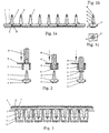
- Figures 1a to 1c illustrate a comb-like straight strip 1, provided with vertical teeth 2 spaced according to the pitch of the test tube or cuvette matrix 3 (figure 3).
- the number of teeth 2 corresponds for example to the number of the wells in a row of the plate, for instance a microtitration plate.
- Each tooth head is advantageously designed so that it includes a sharp, paper-cutting peak 4, and hooking barbs 5 on opposite sides. In the longitudinal direction of the barbs, the peak of the tooth 2 is somewhat longer than in the transversal direction thereof.
- the strip 1 can be provided with an indentation 6 or other gripping or shifting member needed for the transfer, as well as with centering means 7 for centering the strip 1 in the cuvette matrix 3.
- Figure 2 illustrates how in the method according to the invention, a filter paper 8 or other porous plate saturated with a sample is set on top of a punching bed 9, whereafter the user either pulls the lever of a manually operated device, or presses the button or pedal (16) of an automatic device (figure 4, figure 5a), in which case the punching tool 10 cuts out of the paper 8 a sample, most advantageously a round sample 11, shifts it towards the tooth 2, which penetrates the paper 11 simultaneously as the barbs 5 fasten the sample disk 11 onto the tooth 2.
- the punching tool 10 returns to the top position, and the strip 1 can be shifted, either manually or automatically, by means of a grip member such as an indentation 6, forward for the length of an interval according to the pitch of the teeth, as far as the next tooth, and the next cutting step may begin.
- a grip member such as an indentation 6
- Figure 3 illustrates how a matrix formed of the teeth 2 of the strip 1 is partly or completely loaded with sample disks 11 and turned upside down to a cuvette matrix 3, in which case the sample disks 11 are submerged in the elution liquid or reagent 12, and the sample of the desired material, such as blood ore serum, is removed from the sample disk.
- the centering means 7 center the teeth 2 in the cuvette matrix 3. After elution, the strip complete with sample disks 11 can be easily removed.
- FIG. 4 illustrates a preferred embodiment of an automatic punching and conveying device.
- an actuator 13 for instance a spindle motor or a pneumatic cylinder, moves a cutting punching tool 10
- another actuator 14 for instance a stepping motor, moves the strip 1 by intermediation of a gear wheel 25.
- Each actuator can be either electric, such as a magnet, a stepping motor or a spindle motor, or alternatively a pneumatic or a hydraulic cylinder or motor.
- the cutting and the moving of the strip 1 is synchronized by means of a electronic card or a control unit 15, which is connected to a press button or foot pedal 16 for starting the cutting process.
- Figures 5 and 5b illustrate a preferred embodiment of an automatic device which is provided with only one motor 13 or other actuator, whereby both the cutting of the paper 8 and the conveying of the strip 1 are performed.
- a gear motor 13 rotates a cam 17, which further presses the punching tool 10 downwardly by intermediation of a lever 18.
- the lever 18 is returned to the top position by means of a lever spring 19, and the punching tool 10 is returned by means of a punching tool spring 20.
- the bent lever 22 is attached to shaft 23, and said shaft 23, along with its alternating motion, during the returning motion of the push bar 21 pulls the gear wheel 25 by intermediation of a one-way clutch 24, and the gear wheel further moves the strip 1 by means of the indentation 6 provided therein.
- the one-way clutch 24 ensures that the gear wheel 25 and the strip 1 only move in one direction.
- the length of the bent lever 22 and the diameter of the gear wheel 25 are chosen so that the strip 1 moves, during the alternating motion of the lever 18, exactly for the length of the pitch of the teeth 2.
- a spring-loaded ball 26 is slipped in the notches 27 provided at the side of the strip 1, thus ensuring that the strip 1 is stopped at a point which corresponds to the pitch of the teeth 2.
- the apparatus may be provided with a vertical slide.
- the tooth rack 1 can also be provided with a position sensor, for example a hole at the other end thereof, which ensures that the rack is put in the device in the correct position, and that the order of the sample disks attached in the teeth 2 of the comb is known, as well as the corresponding order of patients.
- a position sensor for example a hole at the other end thereof, which ensures that the rack is put in the device in the correct position, and that the order of the sample disks attached in the teeth 2 of the comb is known, as well as the corresponding order of patients.
Landscapes
- Chemical & Material Sciences (AREA)
- Health & Medical Sciences (AREA)
- Biochemistry (AREA)
- Physics & Mathematics (AREA)
- Life Sciences & Earth Sciences (AREA)
- Analytical Chemistry (AREA)
- Chemical Kinetics & Catalysis (AREA)
- General Health & Medical Sciences (AREA)
- General Physics & Mathematics (AREA)
- Immunology (AREA)
- Pathology (AREA)
- Clinical Laboratory Science (AREA)
- Automatic Analysis And Handling Materials Therefor (AREA)
- Sampling And Sample Adjustment (AREA)
Abstract
Description
- The present invention relates to laboratory technology and in particular to a method of analysis where in a porous, sheet-like material, such as filter paper, there is absorbed a sample, such as a specimen of dried blood, of which material there is cut a disk, which disk is then conveyed to a vessel or a vessel matrix, such as a set of test tubes or cuvettes, where the sample disk is eluted. After elution, the sample disk can be removed, and the obtained solution is subjected to the analysis in question.
- In the above described tasks for conveying a sample disk into a reaction vessel and for removing it therefrom, there are generally used a pair of tweezers, and the method requires a lot of manual work. The analyses are usually carried out in series, for instance on a microtitration plate, in which case the analysis is made simultaneously in each well of the plate. The US patent publication 5,474,742 introduces an apparatus whereby sample disks can be simultaneously inserted in and removed from all wells on the plate. The apparatus comprises a framework with arms for each well, and the bottom part of each arm is provided with a shelf-like sample disk retainer. The US patent publication 5,146,794 introduces a system comprising a plurality of tools with a cutting edge and a piercing member. A sample disk is punched from a sheet and attached to the piercing member.
- The method and apparatus according to the invention is designed to facilitate and speed up the conveying of samples of the described type in and out of the vessel of analysis.
- We have now invented a method and apparatus according to the independent claims. Other claims represent a few preferred embodiments of the invention.
- According to the invention, a sample disk is attached to a tooth, where it is conveyed to the reaction vessel. The sample disk can also be removed from the vessel by the tooth. One rack may contain several teeth, corresponding to the pitch of the cuvettes provided in the plate used in the analysis, which further facilitates the task of performing several analyses in series.
- The tooth may include a sharp, cutting part, in which case the tooth penetrates the sheet with as little damage as possible. Moreover, the tooth may include barbs in order to improve the grip.
- The sample disk is cut of a larger sheet by punching it directly onto the tooth. In this fashion, less steps are needed in the process. The punching is advantageously carried out by pushing the punching tool downwardly, against the sample sheet.
- The apparatus may include means for shifting the tooth rack, preferably automatically, for the length of a tooth interval at a time. The apparatus may also include means for ensuring an accurate position for the shifted rack.
- In order to shift the rack, it may contain a suitable grip member, such as an indentation.
- A combined sample disk punching and fastening can be realized by means of separate actuators, or by means of one and the same actuator.
- A preferred embodiment of the present invention is explained in more detail below. The accompanying drawings form part of the description. In the drawings
- figure 1a
- illustrates a tooth rack according to the invention, seen from the side to the teeth of which rack the sample disks are attached,
- figure 1b
- illustrates the tooth rack of figure 1 a from the end,
- figure 1c
- illustrates one tooth of the rack of figure 1a from the top,
- figure 2
- illustrates the different stages of attaching the sample disk to the tooth,
- figure 3
- illustrates a tooth rack installed in a set of cuvettes,
- figure 4
- illustrates an apparatus according to the invention, provided with separate actuators for attaching the sample disk and for moving the tooth rack,
- figure 5a
- illustrates from the side an apparatus according to the invention, provided with only one actuator both for attaching the sample disk and for moving the tooth rack, and
- figure 5b
- illustrates the apparatus of figure 5a from the end.
- Figures 1a to 1c illustrate a comb-like
straight strip 1, provided withvertical teeth 2 spaced according to the pitch of the test tube or cuvette matrix 3 (figure 3). The number ofteeth 2 corresponds for example to the number of the wells in a row of the plate, for instance a microtitration plate. Each tooth head is advantageously designed so that it includes a sharp, paper-cutting peak 4, and hookingbarbs 5 on opposite sides. In the longitudinal direction of the barbs, the peak of thetooth 2 is somewhat longer than in the transversal direction thereof. Thestrip 1 can be provided with anindentation 6 or other gripping or shifting member needed for the transfer, as well as withcentering means 7 for centering thestrip 1 in thecuvette matrix 3. - Figure 2 illustrates how in the method according to the invention, a
filter paper 8 or other porous plate saturated with a sample is set on top of apunching bed 9, whereafter the user either pulls the lever of a manually operated device, or presses the button or pedal (16) of an automatic device (figure 4, figure 5a), in which case thepunching tool 10 cuts out of the paper 8 a sample, most advantageously around sample 11, shifts it towards thetooth 2, which penetrates thepaper 11 simultaneously as thebarbs 5 fasten thesample disk 11 onto thetooth 2. Thereafter thepunching tool 10 returns to the top position, and thestrip 1 can be shifted, either manually or automatically, by means of a grip member such as anindentation 6, forward for the length of an interval according to the pitch of the teeth, as far as the next tooth, and the next cutting step may begin. - Figure 3 illustrates how a matrix formed of the
teeth 2 of thestrip 1 is partly or completely loaded withsample disks 11 and turned upside down to acuvette matrix 3, in which case thesample disks 11 are submerged in the elution liquid orreagent 12, and the sample of the desired material, such as blood ore serum, is removed from the sample disk. The centering means 7 center theteeth 2 in thecuvette matrix 3. After elution, the strip complete withsample disks 11 can be easily removed. - Figure 4 illustrates a preferred embodiment of an automatic punching and conveying device. There an
actuator 13, for instance a spindle motor or a pneumatic cylinder, moves acutting punching tool 10, and anotheractuator 14, for instance a stepping motor, moves thestrip 1 by intermediation of agear wheel 25. Each actuator can be either electric, such as a magnet, a stepping motor or a spindle motor, or alternatively a pneumatic or a hydraulic cylinder or motor. The cutting and the moving of thestrip 1 is synchronized by means of a electronic card or acontrol unit 15, which is connected to a press button orfoot pedal 16 for starting the cutting process. - Figures 5 and 5b illustrate a preferred embodiment of an automatic device which is provided with only one
motor 13 or other actuator, whereby both the cutting of thepaper 8 and the conveying of thestrip 1 are performed. For instance agear motor 13 rotates acam 17, which further presses thepunching tool 10 downwardly by intermediation of alever 18. Thelever 18 is returned to the top position by means of alever spring 19, and thepunching tool 10 is returned by means of apunching tool spring 20. - To the
lever 18, there is geared apush bar 21, the bottom end whereof moves thebent lever 22 back and forth. Thebent lever 22 is attached toshaft 23, and saidshaft 23, along with its alternating motion, during the returning motion of thepush bar 21 pulls thegear wheel 25 by intermediation of a one-way clutch 24, and the gear wheel further moves thestrip 1 by means of theindentation 6 provided therein. Thus the one-way clutch 24 ensures that thegear wheel 25 and thestrip 1 only move in one direction. The length of thebent lever 22 and the diameter of thegear wheel 25 are chosen so that thestrip 1 moves, during the alternating motion of thelever 18, exactly for the length of the pitch of theteeth 2. A spring-loadedball 26 is slipped in thenotches 27 provided at the side of thestrip 1, thus ensuring that thestrip 1 is stopped at a point which corresponds to the pitch of theteeth 2. - Instead of the
lever 18, the apparatus may be provided with a vertical slide. - The
tooth rack 1 can also be provided with a position sensor, for example a hole at the other end thereof, which ensures that the rack is put in the device in the correct position, and that the order of the sample disks attached in theteeth 2 of the comb is known, as well as the corresponding order of patients.
Claims (17)
- A method for punching a sample disk of a larger sheet and conveying it to a reaction vessel, comprising attaching the sample disk to a tooth (2) and conveying the tooth (2) with the sample disk to the reaction vessel, characterized in that the sample disk is attached directly onto the tooth by pushing a punching tool (10) against the sample sheet.
- Use of a method according to claim 1 for conveying a sample disk containing a specimen of blood or serum
- An apparatus for punching a sample disk of a larger sheet and conveying it to a reaction vessel, wherein the apparatus comprises a rack (1) provided with a tooth (2) for fastening the sample disk, characterized in that the apparatus comprises a punching tool (10) for punching the sample disk of the sheet and for attaching it directly onto the tooth (2).
- An apparatus according to claim 3, wherein the rack (1) is provided with a plurality of teeth (2) for fastening sample disks.
- An apparatus according to 4, wherein the rack is provided with teeth (2) in a row.
- An apparatus according to claim 5, wherein the teeth (2) are at a constant pitch.
- An apparatus according to claim 6, wherein the apparatus comprises means (14; 25) for shifting the rack for a length according to the pitch.
- An apparatus according to claim 7, wherein the apparatus comprises means (14; 25) for shifting the rack automatically.
- An apparatus according to any of claims 3 to 8, wherein the tooth or each of the teeth has, respectively, a sharp peak (4).
- An apparatus according to any of claims 3 to 9, wherein the tooth or each of the teeth has, respectively, a cutting peak (4).
- An apparatus according to claim 9 or 10, wherein the tooth or each of the teeth has barbs (5) for fastening the sample disk.
- An apparatus according to any of claims 3 to 11, wherein the rack (1) comprises grip members (6) in order to convey the rack.
- An apparatus according to claim 12, wherein the grip members comprise an indentation (6).
- An apparatus according to any of claims 3 to 13, wherein the apparatus comprises one motor (13) for shifting the rack.
- An apparatus according to claim 14, wherein the apparatus comprises a punching tool (10) working with an alternating motion, so that from the alternating motion of the punching tool, there is provided lever transmission through a one-way clutch to a gear wheel (25), which moves the rack (1) forward in a stepping fashion.
- An apparatus according to any of claims 3 to 15, wherein apparatus comprises means (26; 27) for ensuring an accurate position of the rack (1).
- An apparatus according to claim 16, wherein the rack comprises notches (27), and a spring-loaded ball (26) is provided in order to ensure the accurate position.
Applications Claiming Priority (3)
| Application Number | Priority Date | Filing Date | Title |
|---|---|---|---|
| FI982720 | 1998-12-16 | ||
| FI982720A FI982720A7 (en) | 1998-12-16 | 1998-12-16 | Method and apparatus for transferring a sample to a sample container |
| PCT/FI1999/001035 WO2000036392A1 (en) | 1998-12-16 | 1999-12-15 | Method and apparatus for conveying a sample to a sample vessel |
Publications (2)
| Publication Number | Publication Date |
|---|---|
| EP1062491A1 EP1062491A1 (en) | 2000-12-27 |
| EP1062491B1 true EP1062491B1 (en) | 2005-06-08 |
Family
ID=8553126
Family Applications (1)
| Application Number | Title | Priority Date | Filing Date |
|---|---|---|---|
| EP99963604A Expired - Lifetime EP1062491B1 (en) | 1998-12-16 | 1999-12-15 | Method and apparatus for conveying a sample to a sample vessel |
Country Status (9)
| Country | Link |
|---|---|
| US (1) | US6372504B1 (en) |
| EP (1) | EP1062491B1 (en) |
| CN (1) | CN1291283A (en) |
| AT (1) | ATE297547T1 (en) |
| AU (1) | AU1984500A (en) |
| DE (1) | DE69925717D1 (en) |
| FI (1) | FI982720A7 (en) |
| RU (1) | RU2197719C2 (en) |
| WO (1) | WO2000036392A1 (en) |
Families Citing this family (14)
| Publication number | Priority date | Publication date | Assignee | Title |
|---|---|---|---|---|
| US20060182657A1 (en) * | 2005-02-11 | 2006-08-17 | Whatman, Inc. | Devices and methods for handling and processing punches |
| GB0503986D0 (en) * | 2005-02-26 | 2005-04-06 | Secr Defence | Reaction apparatus |
| US8685749B2 (en) | 2009-12-02 | 2014-04-01 | Whatman International Limited | Methods and systems for processing samples on porous substrates |
| US8689649B2 (en) * | 2009-12-04 | 2014-04-08 | General Electric Company | Methods and systems to prevent punch loss during automated sample processing |
| US9321095B2 (en) | 2010-06-30 | 2016-04-26 | General Electric Company | Apparatuses and methods for cutting porous substrates |
| GB201102009D0 (en) * | 2011-02-07 | 2011-03-23 | Ge Healthcare Uk Ltd | Biological sample holder and method of assembling a storage device |
| DE102011075036A1 (en) * | 2011-04-29 | 2012-10-31 | Hamilton Bonaduz Ag | Punching device with gripping unit |
| CN103196721A (en) * | 2013-03-19 | 2013-07-10 | 广州市丰华生物工程有限公司 | Blood slide bracket |
| CN103217325B (en) * | 2013-04-11 | 2016-01-20 | 广州市丰华生物工程有限公司 | A kind of blood plate rack carries seat and blood plate rack assembly |
| WO2014110887A1 (en) * | 2013-01-21 | 2014-07-24 | 广州市丰华生物工程有限公司 | Blood slide bracket, blood slide bracket assembly, filter paper dried blood slide punching machine, and application of blood slide bracket in in-vitro diagnostic reagent |
| AU2015243618B2 (en) * | 2014-04-09 | 2018-09-20 | Inpeco SA | Modified device for transporting a container of biological products in a laboratory automation system |
| EP3006943B1 (en) * | 2014-10-07 | 2020-04-22 | Roche Diagniostics GmbH | Module for a laboratory sample distribution system, laboratory sample distribution system and laboratory automation system |
| DE102014019526B4 (en) * | 2014-12-23 | 2016-10-27 | Testo Ag | Examination procedure, disk-shaped sample carrier and use of a sample carrier |
| KR102347892B1 (en) * | 2017-08-30 | 2022-01-05 | 임프리메드 인코퍼레이티드 | Products for high-throughput screening of chemical and biochemical compounds |
Family Cites Families (8)
| Publication number | Priority date | Publication date | Assignee | Title |
|---|---|---|---|---|
| US4341735A (en) | 1980-03-28 | 1982-07-27 | American Cyanamid Company | Sample carrier material handling apparatus |
| US5146794A (en) | 1988-03-17 | 1992-09-15 | Millipore Corporation | Filter punch and filter collection system |
| US5510081A (en) * | 1991-11-13 | 1996-04-23 | Queensland University Of Technology | Test sampling apparatus |
| FI922687A0 (en) * | 1992-06-10 | 1992-06-10 | Labsystems Oy | AVLAEGSNINGSANORDNING. |
| FI923220L (en) * | 1992-07-14 | 1994-01-15 | Wallac Oy | FOERFARANDE OCH APPARATUR FOER HANTERING AV PROV SAMT PROVUPPSAMLINGSSYSTEM |
| US5638170A (en) * | 1994-06-07 | 1997-06-10 | Hudson Control Group, Inc. | Punched carrier specimen sample processor |
| US5641682A (en) * | 1995-08-14 | 1997-06-24 | Ortho Pharmaceutical Corporation | Apparatus and method for automatically processing dried blood spots in HIV-1 testing |
| US5862729A (en) * | 1995-10-10 | 1999-01-26 | Ortho Pharmaceutical Corporation | Mechanical punch apparatus and method of using same |
-
1998
- 1998-12-16 FI FI982720A patent/FI982720A7/en unknown
-
1999
- 1999-09-24 US US09/405,168 patent/US6372504B1/en not_active Expired - Fee Related
- 1999-12-15 AU AU19845/00A patent/AU1984500A/en not_active Abandoned
- 1999-12-15 EP EP99963604A patent/EP1062491B1/en not_active Expired - Lifetime
- 1999-12-15 DE DE69925717T patent/DE69925717D1/en not_active Expired - Lifetime
- 1999-12-15 RU RU2000121985/12A patent/RU2197719C2/en not_active IP Right Cessation
- 1999-12-15 AT AT99963604T patent/ATE297547T1/en not_active IP Right Cessation
- 1999-12-15 WO PCT/FI1999/001035 patent/WO2000036392A1/en not_active Ceased
- 1999-12-15 CN CN99803008.2A patent/CN1291283A/en active Pending
Also Published As
| Publication number | Publication date |
|---|---|
| FI982720A7 (en) | 2000-06-17 |
| AU1984500A (en) | 2000-07-03 |
| DE69925717D1 (en) | 2005-07-14 |
| CN1291283A (en) | 2001-04-11 |
| US6372504B1 (en) | 2002-04-16 |
| WO2000036392A1 (en) | 2000-06-22 |
| FI982720A0 (en) | 1998-12-16 |
| EP1062491A1 (en) | 2000-12-27 |
| ATE297547T1 (en) | 2005-06-15 |
| RU2197719C2 (en) | 2003-01-27 |
Similar Documents
| Publication | Publication Date | Title |
|---|---|---|
| US6372504B1 (en) | Method and apparatus for conveying a sample to a sample vessel | |
| US4731225A (en) | Automatic analysis apparatus | |
| DE2755334C3 (en) | System for the automatic analysis of liquid samples | |
| US5736102A (en) | Test sample positioning system | |
| DE69904726T2 (en) | AUTOMATIC IMMUNOASSAY DEVICE WITH FLEXIBLE LIFTING ARM | |
| EP2291631B1 (en) | Improvements in devices and methods for tissue handling and embedding | |
| EP0628824B1 (en) | Transport system for fluid analysis instrument | |
| US6878341B2 (en) | Apparatus for the precise location of reaction plates | |
| EP1876451A3 (en) | Handling method of body fluid sample and analysis apparatus using the same | |
| US20010039843A1 (en) | Automatic pipettor with a single-row, multi-channel pipetting head | |
| EP0793100A3 (en) | Method and device for automatic chemical analysis | |
| EP0762125A3 (en) | Automatic analyzing method using a plurality of reagents and apparatus therefor | |
| CA2168010A1 (en) | Tag reagent and assay method | |
| EP0360940A3 (en) | Polynucleotide determination with selectable cleavage sites | |
| WO2007006903A3 (en) | Automated method for preparing blood sample analysis and automated device therefor | |
| EP1538447A3 (en) | Reagent container | |
| DE68905492T2 (en) | AUTOMATIC CHEMICAL ANALYZER. | |
| JP2010505568A (en) | Sample collection system and method for collecting liquid | |
| CN113252917A (en) | A pipetting device for test tubes | |
| US20070258857A1 (en) | Specimen tray | |
| RU2000121985A (en) | METHOD AND DEVICE FOR TRANSPORTING A SAMPLE TO A SAMPLE VESSEL | |
| RU92016293A (en) | METHOD AND DEVICE FOR IMPLEMENTING BIOCHEMICAL REACTIONS | |
| HK1035226A (en) | Method and apparatus for conveying a sample to a sample vessel | |
| CN217332494U (en) | Liquid transfer device for test tube | |
| JP2002518002A (en) | Biological sample collection and transfer device |
Legal Events
| Date | Code | Title | Description |
|---|---|---|---|
| PUAI | Public reference made under article 153(3) epc to a published international application that has entered the european phase |
Free format text: ORIGINAL CODE: 0009012 |
|
| 17P | Request for examination filed |
Effective date: 20000915 |
|
| AK | Designated contracting states |
Kind code of ref document: A1 Designated state(s): AT BE CH CY DE DK ES FI FR GB GR IE IT LI LU MC NL PT SE |
|
| 17Q | First examination report despatched |
Effective date: 20031127 |
|
| RAP1 | Party data changed (applicant data changed or rights of an application transferred) |
Owner name: THERMO ELECTRON OY |
|
| GRAP | Despatch of communication of intention to grant a patent |
Free format text: ORIGINAL CODE: EPIDOSNIGR1 |
|
| GRAS | Grant fee paid |
Free format text: ORIGINAL CODE: EPIDOSNIGR3 |
|
| GRAA | (expected) grant |
Free format text: ORIGINAL CODE: 0009210 |
|
| AK | Designated contracting states |
Kind code of ref document: B1 Designated state(s): AT BE CH CY DE DK ES FI FR GB GR IE IT LI LU MC NL PT SE |
|
| PG25 | Lapsed in a contracting state [announced via postgrant information from national office to epo] |
Ref country code: NL Free format text: LAPSE BECAUSE OF FAILURE TO SUBMIT A TRANSLATION OF THE DESCRIPTION OR TO PAY THE FEE WITHIN THE PRESCRIBED TIME-LIMIT Effective date: 20050608 Ref country code: LI Free format text: LAPSE BECAUSE OF FAILURE TO SUBMIT A TRANSLATION OF THE DESCRIPTION OR TO PAY THE FEE WITHIN THE PRESCRIBED TIME-LIMIT Effective date: 20050608 Ref country code: IT Free format text: LAPSE BECAUSE OF FAILURE TO SUBMIT A TRANSLATION OF THE DESCRIPTION OR TO PAY THE FEE WITHIN THE PRESCRIBED TIME-LIMIT;WARNING: LAPSES OF ITALIAN PATENTS WITH EFFECTIVE DATE BEFORE 2007 MAY HAVE OCCURRED AT ANY TIME BEFORE 2007. THE CORRECT EFFECTIVE DATE MAY BE DIFFERENT FROM THE ONE RECORDED. Effective date: 20050608 Ref country code: FI Free format text: LAPSE BECAUSE OF FAILURE TO SUBMIT A TRANSLATION OF THE DESCRIPTION OR TO PAY THE FEE WITHIN THE PRESCRIBED TIME-LIMIT Effective date: 20050608 Ref country code: ES Free format text: LAPSE BECAUSE OF FAILURE TO SUBMIT A TRANSLATION OF THE DESCRIPTION OR TO PAY THE FEE WITHIN THE PRESCRIBED TIME-LIMIT Effective date: 20050608 Ref country code: CH Free format text: LAPSE BECAUSE OF FAILURE TO SUBMIT A TRANSLATION OF THE DESCRIPTION OR TO PAY THE FEE WITHIN THE PRESCRIBED TIME-LIMIT Effective date: 20050608 Ref country code: BE Free format text: LAPSE BECAUSE OF FAILURE TO SUBMIT A TRANSLATION OF THE DESCRIPTION OR TO PAY THE FEE WITHIN THE PRESCRIBED TIME-LIMIT Effective date: 20050608 Ref country code: AT Free format text: LAPSE BECAUSE OF FAILURE TO SUBMIT A TRANSLATION OF THE DESCRIPTION OR TO PAY THE FEE WITHIN THE PRESCRIBED TIME-LIMIT Effective date: 20050608 |
|
| REG | Reference to a national code |
Ref country code: GB Ref legal event code: FG4D |
|
| REG | Reference to a national code |
Ref country code: CH Ref legal event code: EP |
|
| REF | Corresponds to: |
Ref document number: 69925717 Country of ref document: DE Date of ref document: 20050714 Kind code of ref document: P |
|
| REG | Reference to a national code |
Ref country code: IE Ref legal event code: FG4D |
|
| PG25 | Lapsed in a contracting state [announced via postgrant information from national office to epo] |
Ref country code: SE Free format text: LAPSE BECAUSE OF FAILURE TO SUBMIT A TRANSLATION OF THE DESCRIPTION OR TO PAY THE FEE WITHIN THE PRESCRIBED TIME-LIMIT Effective date: 20050908 Ref country code: GR Free format text: LAPSE BECAUSE OF FAILURE TO SUBMIT A TRANSLATION OF THE DESCRIPTION OR TO PAY THE FEE WITHIN THE PRESCRIBED TIME-LIMIT Effective date: 20050908 Ref country code: DK Free format text: LAPSE BECAUSE OF FAILURE TO SUBMIT A TRANSLATION OF THE DESCRIPTION OR TO PAY THE FEE WITHIN THE PRESCRIBED TIME-LIMIT Effective date: 20050908 |
|
| PG25 | Lapsed in a contracting state [announced via postgrant information from national office to epo] |
Ref country code: DE Free format text: LAPSE BECAUSE OF FAILURE TO SUBMIT A TRANSLATION OF THE DESCRIPTION OR TO PAY THE FEE WITHIN THE PRESCRIBED TIME-LIMIT Effective date: 20050909 |
|
| PG25 | Lapsed in a contracting state [announced via postgrant information from national office to epo] |
Ref country code: PT Free format text: LAPSE BECAUSE OF FAILURE TO SUBMIT A TRANSLATION OF THE DESCRIPTION OR TO PAY THE FEE WITHIN THE PRESCRIBED TIME-LIMIT Effective date: 20051114 |
|
| NLV1 | Nl: lapsed or annulled due to failure to fulfill the requirements of art. 29p and 29m of the patents act | ||
| PG25 | Lapsed in a contracting state [announced via postgrant information from national office to epo] |
Ref country code: IE Free format text: LAPSE BECAUSE OF NON-PAYMENT OF DUE FEES Effective date: 20051215 Ref country code: GB Free format text: LAPSE BECAUSE OF NON-PAYMENT OF DUE FEES Effective date: 20051215 Ref country code: CY Free format text: LAPSE BECAUSE OF FAILURE TO SUBMIT A TRANSLATION OF THE DESCRIPTION OR TO PAY THE FEE WITHIN THE PRESCRIBED TIME-LIMIT Effective date: 20051215 |
|
| REG | Reference to a national code |
Ref country code: CH Ref legal event code: PL |
|
| PG25 | Lapsed in a contracting state [announced via postgrant information from national office to epo] |
Ref country code: MC Free format text: LAPSE BECAUSE OF NON-PAYMENT OF DUE FEES Effective date: 20051231 Ref country code: LU Free format text: LAPSE BECAUSE OF NON-PAYMENT OF DUE FEES Effective date: 20051231 |
|
| PLBE | No opposition filed within time limit |
Free format text: ORIGINAL CODE: 0009261 |
|
| STAA | Information on the status of an ep patent application or granted ep patent |
Free format text: STATUS: NO OPPOSITION FILED WITHIN TIME LIMIT |
|
| 26N | No opposition filed |
Effective date: 20060309 |
|
| EN | Fr: translation not filed | ||
| PG25 | Lapsed in a contracting state [announced via postgrant information from national office to epo] |
Ref country code: FR Free format text: LAPSE BECAUSE OF FAILURE TO SUBMIT A TRANSLATION OF THE DESCRIPTION OR TO PAY THE FEE WITHIN THE PRESCRIBED TIME-LIMIT Effective date: 20060804 |
|
| GBPC | Gb: european patent ceased through non-payment of renewal fee |
Effective date: 20051215 |
|
| REG | Reference to a national code |
Ref country code: IE Ref legal event code: MM4A |
|
| PG25 | Lapsed in a contracting state [announced via postgrant information from national office to epo] |
Ref country code: FR Free format text: LAPSE BECAUSE OF FAILURE TO SUBMIT A TRANSLATION OF THE DESCRIPTION OR TO PAY THE FEE WITHIN THE PRESCRIBED TIME-LIMIT Effective date: 20050608 |