EP1061698A2 - Method and apparatus for forecasting and controlling congestion in a data transport network - Google Patents
Method and apparatus for forecasting and controlling congestion in a data transport network Download PDFInfo
- Publication number
- EP1061698A2 EP1061698A2 EP00305032A EP00305032A EP1061698A2 EP 1061698 A2 EP1061698 A2 EP 1061698A2 EP 00305032 A EP00305032 A EP 00305032A EP 00305032 A EP00305032 A EP 00305032A EP 1061698 A2 EP1061698 A2 EP 1061698A2
- Authority
- EP
- European Patent Office
- Prior art keywords
- node
- network
- input
- data
- congestion
- Prior art date
- Legal status (The legal status is an assumption and is not a legal conclusion. Google has not performed a legal analysis and makes no representation as to the accuracy of the status listed.)
- Withdrawn
Links
Images



Classifications
-
- H—ELECTRICITY
- H04—ELECTRIC COMMUNICATION TECHNIQUE
- H04L—TRANSMISSION OF DIGITAL INFORMATION, e.g. TELEGRAPHIC COMMUNICATION
- H04L47/00—Traffic control in data switching networks
- H04L47/10—Flow control; Congestion control
- H04L47/27—Evaluation or update of window size, e.g. using information derived from acknowledged [ACK] packets
-
- H—ELECTRICITY
- H04—ELECTRIC COMMUNICATION TECHNIQUE
- H04L—TRANSMISSION OF DIGITAL INFORMATION, e.g. TELEGRAPHIC COMMUNICATION
- H04L47/00—Traffic control in data switching networks
- H04L47/10—Flow control; Congestion control
-
- H—ELECTRICITY
- H04—ELECTRIC COMMUNICATION TECHNIQUE
- H04L—TRANSMISSION OF DIGITAL INFORMATION, e.g. TELEGRAPHIC COMMUNICATION
- H04L47/00—Traffic control in data switching networks
- H04L47/10—Flow control; Congestion control
- H04L47/26—Flow control; Congestion control using explicit feedback to the source, e.g. choke packets
- H04L47/263—Rate modification at the source after receiving feedback
-
- H—ELECTRICITY
- H04—ELECTRIC COMMUNICATION TECHNIQUE
- H04L—TRANSMISSION OF DIGITAL INFORMATION, e.g. TELEGRAPHIC COMMUNICATION
- H04L47/00—Traffic control in data switching networks
- H04L47/10—Flow control; Congestion control
- H04L47/30—Flow control; Congestion control in combination with information about buffer occupancy at either end or at transit nodes
-
- Y—GENERAL TAGGING OF NEW TECHNOLOGICAL DEVELOPMENTS; GENERAL TAGGING OF CROSS-SECTIONAL TECHNOLOGIES SPANNING OVER SEVERAL SECTIONS OF THE IPC; TECHNICAL SUBJECTS COVERED BY FORMER USPC CROSS-REFERENCE ART COLLECTIONS [XRACs] AND DIGESTS
- Y02—TECHNOLOGIES OR APPLICATIONS FOR MITIGATION OR ADAPTATION AGAINST CLIMATE CHANGE
- Y02D—CLIMATE CHANGE MITIGATION TECHNOLOGIES IN INFORMATION AND COMMUNICATION TECHNOLOGIES [ICT], I.E. INFORMATION AND COMMUNICATION TECHNOLOGIES AIMING AT THE REDUCTION OF THEIR OWN ENERGY USE
- Y02D30/00—Reducing energy consumption in communication networks
- Y02D30/50—Reducing energy consumption in communication networks in wire-line communication networks, e.g. low power modes or reduced link rate
Definitions
- the present invention relates to the field of digital data transmission. More specifically, it pertains to a method and apparatus for forecasting and controlling congestion within a data transport network, such as a standard routed network or an add/drop packet network.
- a data transport network such as a standard routed network or an add/drop packet network.
- bandwidth sharing between the network trunks be well managed so as to avoid congestion.
- Prior art mechanisms for avoiding congestion within a data network include a centralized management scheme or a complex system for interchange of information implemented within the transport network.
- One such system for interchange of information is equivalent to the bidding for space on the common transport medium by the various network nodes, where the bidding performed by a particular node is based on the amount of data traffic at that particular node. The amount of data traffic may be evaluated on the basis of queue length at the particular node.
- Such schemes do not cater to the fact that the data sources (nodes) are themselves adaptive and that queue lengths at the inputs to the transport medium are not an indication of potential demand. This reduces the effectiveness and accurateness of these congestion mechanisms, such that congestion may still exist within the transport network.
- a node for use in a data network comprising:
- the node of the invention enables a level of data occupancy of at least a portion of the network to be estimated by looking at the traffic units received from a remote node in the network.
- the level of data occupancy is representative of the amount of data being carried by the network portion being evaluated and reflects the level of congestion in the network portion of interest.
- the node evaluates the data occupancy level of a certain portion of the network and compares it against a threshold.
- This threshold is dynamic and varies on the basis of the rate of release from that node of traffic units input in the node from a local source.
- the node issues a control signal that is sent to the remote node.
- the control signal is a congestion stamp placed into a certain traffic unit before its release from the node into the network.
- the control signal is a notification to the remote node to reduce the output of traffic units into the network.
- the traffic units in the data network may be either user data packets, control packets or compound packets having a user data part and a control part.
- the user data packets and the user data parts of the compound packets carry mostly user payload data, such as speech samples, video samples or other.
- the control packets and control parts of the compound packets carry control information, such as source and destination identifiers, control sequence numbers and reverse direction acknowledgements.
- the traffic units used to evaluate the data occupancy level within the network are control packets.
- the present invention also encompasses a method for controlling the congestion at a node in a data network.
- the method comprises the steps of estimating a data occupancy level of at least a portion of the data network based at least on a rate of traffic units passing from through the node, and taking an appropriate action in an attempt to reduce congestion (if congestion exists).
- FIG. 1 illustrates a typical ring-based transport network 100, where the transport ring 102 interconnects a plurality of nodes 104, 106, 108, 110, 112 and 114.
- Each node includes an input/output pair corresponding to one direction of the ring 102, where the input is for receiving traffic units from the ring 102 and the output is for releasing traffic units to the ring 102.
- Each connection between an output of one node and an input node of another, remote node is defined as a trunk.
- the endpoints of such a trunk may be referred to as sender (originator of the data be ing sent over the trunk) and receiver (destination of the data being sent over the trunk).
- sender originator of the data be ing sent over the trunk
- receiver destination of the data being sent over the trunk
- the connection between output 118 of node 104 (sender) and input 132 of node 112 (receiver) is a trunk A
- the connection between output 156 of node 108 (sender) and input 142 of node 114 (receiver) is a trunk B. Since the transport ring 102 is a medium that is common to all of the nodes, the trunks formed between these nodes must share the total bandwidth available over the transport ring 102.
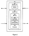
- each of the transport ring 102 nodes generally includes a control unit 200 and a storage unit 202; assume for this example that we are looking at node 104.
- the control unit 200 includes a memory 204 and a processor 206, and is responsible for controlling the flow of traffic units inserted by the node 104 onto the transport ring 102.
- Control unit 200 further implements a congestion control mechanism based on the amount of traffic being carried by the transport ring 102, such that congestion at the node is foreseen and avoided or at least reduced, as will be described in further detail below.
- the congestion control mechanism is implemented by software executed by the processor 206.
- the storage unit 202 includes a plurality of buffers (queues) for receiving and storing data arriving at node 104 from local sources, where the traffic from these buffers is to be transported over respective trunks of the transport ring 102.
- the storage unit 202 is the actual physical storage facility where traffic units are handled.
- the memory 204 is also a physical storage device, it is used primarily for control purposes. This distinction is not critical to the present invention and an embodiment where a single storage medium is provided that combines the memory 204 and the storage unit 202 can clearly be envisaged.
- the traffic units in the data network may be either user data packets, control packets or compound packets having a user data part and a control part.
- the user data packets and the user data parts of the compound packets carry mostly user payload data, such as speech samples, video samples or other.
- the control packets and control parts of the compound packets carry control information, such as source and destination identifiers, control sequence numbers and reverse direction acknowledgements. Note that in addition to user payload data a user data packet may contain some form of control element, for example an identifier representative of a companion control packet.
- the memory 204 of the control unit 200 includes two queues 208 and 210, hereafter referred to as real buffer 208 and virtual buffer 210.
- the real buffer 208 receives traffic units from the various local buffers of the storage unit 202, and provides a temporary storage mechanism for holding all traffic units for insertion onto the transport ring 102 until space is available on the ring 102.
- the virtual buffer 210 is used by the control unit 200 to determine whether congestion is or will be experienced by the node 104, and has an effective fill which is equivalent to the amount of space available on the ring 102, or data occupancy level on the ring 102 for receiving traffic from the node 104. The functionality of the virtual buffer 210 will be described in further detail below.
- the memory 204 further contains a program element that regulates the congestion control mechanism of the node 104.
- the program element is comprised of individual instructions that are executed by the processor 206, for evaluating the link occupancy of the transport ring 102 and for reducing the likelihood of congestion at the node. This program element will be described in further detail below.
- a conventional IP network implements bandwidth sharing among host machines using the Transport Control Protocol (TCP).
- TCP Transport Control Protocol
- the sender sender host machine
- TCP the sender host machine
- the general characteristic of TCP is that it is self-clocking. That is to say, the sender will wait for an acknowledgement from the receiver for the packets already sent before sending more packets. If the sender waited for each individual packet to be acknowledged than the maximum rate that the connection could achieve would be one packet per round trip time of the connection.
- the sender is allowed to send some number of packets while waiting for an earlier packet to be acknowledged. This number of packets is called the window.
- the receiver itself may constrain the size of the window in order to limit its buffer requirement.
- the current size of the window is called the congestion window and can vary between one packet and the maximum that the receiver is prepared to accept.
- the window slides forward and also increases in size. An increase in size allows the connection to run faster. If a packet is not acknowledged it will eventually be considered lost and this loss is assumed to be a result of congestion at some merge point.
- the sender in addition to re-transmitting the packet, will reduce the window size. The slow and gradual increase in window size then begins again.
- An embodiment of the present invention uses a mechanism to implement congestion control at a node within a data transport network, where this mechanism has some common points to the TCP process and is thus referred to as a TCP-like mechanism.
- the mechanism comprises the use of an adaptive window scheme, such as that used in TCP, where the adaptive window scheme controls the real data transmission rates.
- the data occupancy level of the network is estimated and regularly updated, such that it may be used to adjust the window size.
- the data network 100 implements a control overlay concept, whereby data control is detached from the user data itself.
- the control overlay concept separates the control information from the user data. Specifically, for every user data packet sent over the transport ring 102, there is a corresponding control packet sent separately by the data control system, which itself emulates the topology of the data network. Note that this emulation of the data network topology may be effected by using the same physical path of the ring 102 as that used by the data stream.
- control packets could use a physical path of the ring 102 that is separate from that used for transporting the actual user data, as long as the control packets travel in reasonable synchronism with the user data packets.
- the control unit 200 will generate and send a control packet over the ring 102 towards the receiver 112, thus emulating the trunk.
- the user data packets and control packets may be merged to form a compound packet, where data control is embedded into the actual user data stream, as in the case of TCP.
- the control packet in a specific example, is a predefined sequence of bit fields containing, but not limited to: a busy/idle indicator for the ring slot of the corresponding data unit; source (sender) and destination (receiver) node identifiers; control sequence numbers; congestion notification; and reverse direction.
- control packets and user data packets form the body of traffic units transiting through the transport ring 102, data control information being separate from the user data stream itself.
- Each node in the ring-based transport network independently assesses the data occupancy level in the network and implements a congestion control mechanism in response to this data occupancy level, in particular if the data occupancy level signals the presence of congestion at the particular node.
- the control unit 200 of node 104 is operative to detect and foresee congestion at the node 104, in response to which it will generate a control signal. In the situation where the node 104 is experiencing congestion, this control signal is effective to reduce the level congestion. In the situation where the node 104 will be experiencing congestion in the future, this control signal is effective to reduce the likelihood of congestion developing at the node 104.
- the control signal generated by the control unit 200 takes the form of a congestion stamp applied to a control packet released from the node 104 to the transport ring 102.
- each control packet has a congestion notification field. As control packets are released in the network, this field is set to a default value "not congested".
- An intermediate node on the path of the trunk followed by a control packet can apply a congestion stamp to the control packet by setting the bits in the congestion notification field of a control packet to "congested", thus indicating that congestion is being experienced or is being forecasted at the intermediate node.
- the receiver will check control packets for this congestion stamp and, if detected, will pass it back to the sender using an outgoing control packet travelling in the reverse direction over the transport ring 102. More specifically, upon receiving a control packet over the transport ring 102, a transport node will check the destination node identifier (receiver address) stored in a predetermined field of the control packet. If the destination node identifier corresponds to that particular transport node, the control packet will then be checked for a congestion stamp. Upon detection of such a stamp, the source node identifier (sender address) will be read from the control packet and the congestion stamp transmitted back to the sender using an outgoing control packet traveling in the direction of the sender.
- the destination node identifier recipient address
- the receiver is a node that is the intended recipient of the user data packet associated with the control packet. In that sense the receiver is different from the intermediate nodes since it generates an acknowledgement for the user data packet (the outgoing control packet mentioned above) to signal to the sender that the information has been correctly received.
- acknowledgement provides a convenient mechanism to transfer back to the sender the congestion stamp acquired by the control packet during its transit through one or more intermediate nodes.
- the sender of the control packet receives the acknowledgment (control packet issued by the receiver), it is notified that congestion exists or is developing in the network.
- the sender can reduce its rate of release of traffic units into the network in order to reduce the congestion.
- control packets typically only a small percentage of the control packets are marked with congestion stamps.
- This isolation between the control information and the actual data stream accommodates implementations such as optical networks where the data control system can be run on a low speed system while the real data can exploit high speed, fixed-length parallel transfers.
- Other implementations provided for include packet-based systems with variable length packets.
- the size of the data packet can be freely chosen as long as it allows for control information (control packets) to be received often enough to suit the goal of the control loop (i.e. the round trip control loop timing of the system). Note that configuring different data packet sizes for different trunks is one way to bias the sharing of available bandwidth between the trunks.
- the sender 104 When the sender 104 receives a control packet marked with a congestion stamp from the receiver 112, it will reduce the size of the TCP-like adaptive window, thus reducing its data-sending rate.
- the sender 104 is aware of the round trip control time for the trunk and need only react to one congestion stamp in that time period.
- the adaptive window control algorithm implemented by the transport ring nodes is based on the above-described TCP model of multiplicative decrease and additive increase. Specifically, the sender 104 will progressively increase its data-sending rate until a congestion stamp is received, at which point it will reduce its data sending rate. In the absence of further congestion stamps, the sender 104 will again start progressively increasing its data-sending rate. This algorithm will not be described in further detail, as it is well documented and well known to those skilled in the art. It should be noted that there are many alternative algorithms for use in implementing the adaptive window control algorithm, also included within the scope of the present invention.
- the transport ring 102 is a slotted ring, wherein each slot on the ring 102 represents a user data packet.
- a slotted ring's data control system involves the use of an information "header", travelling in parallel with the user data packet and carrying basic information such as whether the slot is in use and, if in use, the destination node (receiver) to which it is being sent.
- This header may also carry the control packet that can be marked at any node to indicate congestion.
- the control unit 200 of a node assesses congestion by first determining the data occupancy level of the transport ring 102. This data occupancy level is then compared to a threshold level, where the threshold level is dynamic and varies on the basis of the rate of release of data packets from the real buffer 208 (local sending rate).
- Figure 3 is a functional illustration of the transport node 104, specifically intended to depict how the data occupancy level is established and how congestion is forecasted.
- the control unit 200 checks the incoming information headers at a monitoring point 300 and, for each slot, updates a history of slot status maintained in memory 204.
- the history of slot status maintained in memory 204 includes the number of busy slots passing the monitoring point as well as the number of available slots passing the monitoring point, where these variables are reset upon the expiration of one round trip time of the transport ring 102.
- the control unit 200 treats each idle or previously marked slot as available and all others as busy . Note that a marked slot will result in at least one available slot in the next period.
- this history reveals the data occupancy level of the transport ring 102, that is the amount of data being carried by the transport ring 102.
- the number of available slots occurring in a period equal to one round trip time for the ring is used to produce an effective "fill" of the virtual buffer 210 in memory 204, where having no available slots is equivalent to having 100% fill.
- the virtual buffer 210 fill is below the threshold level, such that the number of available slots on the transport ring 102 is adequate to handle all the traffic that the node 104 wants to send in that period, then there is no congestion. If the number is not adequate, and the fill is above the threshold level, then congestion notification must be invoked, by marking an outgoing control packet with a congestion stamp at a marking point 302.
- the available slot requirement for transport node 104, that is the threshold level is based on the current sending rate of the node 104, or on a future projection of this sending rate.
- the earlier described adaptive window control algorithm ensures that the TCP-like adaptive window growth is very gentle so that the number of available slots seen during one round trip time of the transport ring 102 can be used to project the number available in the next round trip time.
- the threshold level is dynamic in that it reflects the amount of local data that the node is desirous of inputting to the network. The more local data there is to be released by the node 104 to the transport ring 102, the lesser the data occupancy level needed to trigger the congestion control mechanism. Consequently, the threshold level decreases with an increased amount of local data for release by the node 104 to the transport ring 102.
- control unit 200 While implemented separately from the above-described congestion assessment operation, it should be noted that if an information header is indicative of an idle slot, the control unit 200 generates and inserts a control packet into the information header for transmission over the transport ring 102. In addition, a data packet from the real buffer 108 is inserted into the corresponding parallel idle slot for transmission over the transport ring 102.
- FIG. 4 provides a complete flowchart illustrating an example of the operation of the program element stored in the memory 204 of the control unit 200, and executed by the processor 206, that regulates the congestion control mechanism of the transport node 104.
- the control unit 200 monitors the information headers (control traffic) passing through transport node 104. For each information header, the control unit 200 checks to see if the header is marked as being idle or not and updates the history maintained in memory 204 accordingly, at step 404. Based on this history, the number of slots available in a period equal to one round trip time of the ring 102 is determined and the effective fill of virtual buffer 210 is updated at step 406.
- the control unit 200 assesses its congestion situation, using the fill of virtual buffer 210 (data occupancy level) and the threshold level, itself based on the current data sending rate of the transport node 104. If the space required on the transport ring 102 based on the current data sending rate is greater than the available space on the transport ring 102, such that the effective fill of virtual buffer 210 is above the threshold level, an outgoing control packet is marked with a congestion stamp at step 410.
- a mechanism may be used to gradually increase the congestion marking probability, such as is used in Random Early Detection (RED).
- RED Random Early Detection
- the 100% fill of virtual buffer 210 is equated to the maximum threshold of RED (MAXth), while the minimum threshold (MINth) is calculated by subtracting the projected local requirement from MAXth, as shown in Figure 5.
- the buffer fill can be calculated as a weighted average over several round trip times. Since RED is well documented and known to those skilled in the art, it will not be described in further detail.
- the control loop round trip time is identical for all transport nodes and bandwidth sharing between nodes is generally quite fair.
- some correction factors may be required to ensure fair sharing or, as suggested earlier, to deliberately bias sharing toward particular trunks.
- the sharing properties may be biased by adjusting round trip times or by allocating some trunks larger data units.
- the sender node for a particular trunk could be allowed to insert non-modifiable control packets with the basic data packets. If one normal control packet is sent for every three non-modifiable control packets then the trunk has an effective data packet of four times the basic data packet, thus providing the trunk with a greater share of the bandwidth over the transport medium.
- the above-described control overlay concept and use of a virtual buffer to perform congestion assessment at a transport node may be implemented within a standard routed network. Specifically, at each network router congestion may be foreseen and reduced without causing network latency due to data buffering. Rather than buffering all data flowing through the network and using the buffer fill to trigger packet loss, the virtual buffer having a fill representative of the transport medium data occupancy level may be used to implement the congestion control mechanism. Further, the transport medium data occupancy level may be determined by monitoring the control system, itself de-coupled from the data transport system.
Landscapes
- Engineering & Computer Science (AREA)
- Computer Networks & Wireless Communication (AREA)
- Signal Processing (AREA)
- Data Exchanges In Wide-Area Networks (AREA)
- Small-Scale Networks (AREA)
Abstract
Description
- an input for receiving traffic units from a first remote node;
- an output for releasing traffic units to a second remote node;
- a control unit coupled to said input for estimating a data occupancy level of at least a portion of the data network based at least on a rate of traffic units passing from said input to said output, when the data occupancy level reaches a certain threshold said control unit being operative to generate a control signal instrumental to cause a reduction in the data occupancy level.
Claims (23)
- A node for use in a data network, said node comprising:an input for receiving traffic units from a first remote node;an output for releasing traffic units to a second remote node;a control unit coupled to said input for estimating a data occupancy level of at least a portion of the data network based at least on a rate of traffic units passing from said input to said output, when the data occupancy level reaches a certain threshold said control unit being operative to generate a control signal instrumental to cause a reduction in the data occupancy level.
- A node as defined in claim 1, wherein said traffic units are selected from the group consisting of user data packets, control packets and compound packets including a user data part and a control part.
- A node as defined in claim 1 or 2, wherein said control signal is directed to a remote node issuing traffic units towards said input.
- A node as defined in claim 1, 2 or 3, wherein said input is a first input, said node further comprising a second input for receiving traffic units from a local source for transmission to a remote node in the network.
- A node as defined in claim 4, wherein said certain threshold is dynamic and varies on the basis of the rate of release from said node of the traffic units received at said second input.
- A node as defined in claim 5, wherein said traffic units received from a local source for transmission to a remote node in the network are user data packets.
- A node as defined in claim 5 or 6, wherein said control signal includes a congestion stamp placed into a certain traffic unit released from said output.
- A node as defined in claim 7, wherein said certain traffic unit includes a source identifier and a destination identifier, the destination identifier designating a downstream remote node of the network, the source identifier designating an upstream remote node of the network, upon reception of the certain traffic unit at the downstream remote node said congestion stamp being transmitted to the upstream remote node.
- A node as defined in claim 8, wherein said control unit is responsive to a congestion stamp received from a remote node in the network and associated to a user data packet originating from said node to reduce a rate of release from said node of the traffic units received at said second input.
- A node as defined in claim 9, wherein said control unit is operative to progressively increase a rate of release from said node of the traffic units received at said second input until a congestion stamp is received from a remote node in the network.
- A node as defined in claim 10, wherein each of said traffic units received at said first input is either one of a user data packet and a control packet, the control packets being associated with respective use data packet and being transmitted separately from the user data packets in the network.
- A node as defined in claim 11, wherein said control unit estimates a data occupancy level of at least a portion of the data network based at least on a rate of control packets passing from said first input to said output.
- A node as defined in claim 9, wherein the congestion stamp is carried by a control packet received from a remote node in the network.
- A method for controlling congestion at a node in a data network, said node comprising:an input for receiving traffic units from a first remote node;an output for releasing traffic units to a second remote node;
said method comprising:a) estimating a data occupancy level of at least a portion of the data network based at least on a rate of traffic units passing from said input to said output;b) when the data occupancy level reaches a certain threshold generating a control signal instrumental to cause a reduction in the data occupancy level. - A method as defined in claim 14, wherein said traffic units are selected from the group consisting of user data packets, control packets and compound packets including a data part and a control part.
- A method as defined in claim 14 or 15, wherein said control signal is directed to a remote node issuing traffic units towards said input.
- A method as defined in claim 14, 15 or 16, wherein said input is a first input, said node further comprising a second input for receiving traffic units from a local source for transmission to a remote node in the data network.
- A method as defined in claim 17, wherein said certain threshold is dynamic, said method comprising varying said threshold on a basis of a rate of release from said node of traffic units received at said second input.
- A method as defined in claim 17, wherein the traffic units received at said second input are user data packets.
- A method as defined in claim 17, wherein the control signal includes a congestion stamp placed into a certain traffic unit released from said output.
- A method as defined in claim 20, wherein said certain traffic unit includes a source identifier and a destination identifier, the destination identifier designating a downstream remote node of the network, the source identifier designating an upstream remote node of the network, upon reception of the certain traffic unit at the downstream remote node the congestion stamp being transmitted to the upstream remote node.
- A method as defined in claim 21, said method comprising reducing a rate of release from said node of the traffic units received at said second input in response to a congestion stamp received from a remote node in the network.
- A method as defined in claim 22, said method comprising progressively increasing a rate of release from said node of the traffic units received at said second input until a congestion stamp is received from a remote node in the network.
Applications Claiming Priority (2)
| Application Number | Priority Date | Filing Date | Title |
|---|---|---|---|
| US333269 | 1999-06-15 | ||
| US09/333,269 US6922390B1 (en) | 1999-06-15 | 1999-06-15 | Method and apparatus for forecasting and controlling congestion in a data transport network |
Publications (2)
| Publication Number | Publication Date |
|---|---|
| EP1061698A2 true EP1061698A2 (en) | 2000-12-20 |
| EP1061698A3 EP1061698A3 (en) | 2002-09-04 |
Family
ID=23302074
Family Applications (1)
| Application Number | Title | Priority Date | Filing Date |
|---|---|---|---|
| EP00305032A Withdrawn EP1061698A3 (en) | 1999-06-15 | 2000-06-14 | Method and apparatus for forecasting and controlling congestion in a data transport network |
Country Status (4)
| Country | Link |
|---|---|
| US (1) | US6922390B1 (en) |
| EP (1) | EP1061698A3 (en) |
| JP (1) | JP2001024678A (en) |
| CA (1) | CA2299041A1 (en) |
Cited By (5)
| Publication number | Priority date | Publication date | Assignee | Title |
|---|---|---|---|---|
| EP1471695A1 (en) | 2003-03-31 | 2004-10-27 | Lucent Technologies Inc. | Method for flow control in a communication system |
| WO2005020516A1 (en) * | 2003-08-19 | 2005-03-03 | Cisco Technology, Inc. | Systems and methods for alleviating client over-subscription in ring networks |
| EP1703649A1 (en) * | 2005-03-18 | 2006-09-20 | Alcatel | Method for adapting an optical transmission unit to a fixed optical transmission link, optical transmission unit and optical receive unit |
| US7382726B2 (en) * | 2002-11-25 | 2008-06-03 | Electronics And Telecommunications Research Institute | Node system, dual ring communication system using node system, and communication method thereof |
| CN100499858C (en) * | 2003-03-31 | 2009-06-10 | 富士通株式会社 | Radio communication network and flow control method |
Families Citing this family (27)
| Publication number | Priority date | Publication date | Assignee | Title |
|---|---|---|---|---|
| EP1228663A1 (en) * | 1999-11-05 | 2002-08-07 | Nokia Corporation | A method for predicting a fill-up level of a buffer in an atm network element |
| GB0031535D0 (en) * | 2000-12-22 | 2001-02-07 | Nokia Networks Oy | Traffic congestion |
| US7899066B2 (en) * | 2001-01-25 | 2011-03-01 | Alcatel Lucent | Distributed intelligence MAC protocols for DWDM ring networks |
| US7394764B2 (en) * | 2001-12-14 | 2008-07-01 | Sasken Communication Technologies Limited | Technique for improving transmission control protocol performance in lossy networks |
| US7359326B1 (en) * | 2002-02-05 | 2008-04-15 | 3Com Corporation | Method for splitting data and acknowledgements in a TCP session |
| US20030189901A1 (en) * | 2002-04-03 | 2003-10-09 | Timucin Ozugur | Upstream resource management propagation system and method for use in bufferless networks |
| US7317682B2 (en) * | 2003-09-04 | 2008-01-08 | Mitsubishi Electric Research Laboratories, Inc. | Passive and distributed admission control method for ad hoc networks |
| US8724458B2 (en) * | 2004-01-14 | 2014-05-13 | Telefonaktiebolaget L M Ericsson (Publ) | Methods and devices for controlling data unit handling |
| JP4705909B2 (en) * | 2004-03-11 | 2011-06-22 | パナソニック株式会社 | Control station apparatus, base station apparatus, and packet communication method |
| US8081566B1 (en) * | 2004-04-19 | 2011-12-20 | Rockstar BIDCO, LLP | Method and apparatus for indicating congestion in a source routed network |
| US7394797B2 (en) * | 2004-09-02 | 2008-07-01 | Sharp Laboratories Of America, Inc. | Medium sensing histogram for WLAN resource reporting |
| US7719967B2 (en) | 2005-09-28 | 2010-05-18 | Netapp, Inc. | Cumulative TCP congestion control |
| JP4711794B2 (en) * | 2005-09-28 | 2011-06-29 | 富士通株式会社 | Ring network bandwidth changing method and node device |
| FR2894746B1 (en) * | 2005-12-09 | 2008-06-13 | Ipanema Technologies Sa | METHOD AND DEVICE FOR REMOTELY CONTROLLING CONGESTION OF MESH FLOWS IN A PACKET MODE TELECOMMUNICATION NETWORK |
| US7898988B2 (en) * | 2006-01-20 | 2011-03-01 | Harman International Industries, Incorporated | Self annealing auto-expanding network |
| US7733779B2 (en) * | 2006-06-14 | 2010-06-08 | Cisco Technology, Inc. | Stateless call admission and call preemption with a single metering and marking scheme |
| US7729249B2 (en) | 2007-07-16 | 2010-06-01 | Microsoft Corporation | Systems and methods for improving TCP-friendliness of delay-based congestion control |
| JP5191826B2 (en) * | 2008-07-04 | 2013-05-08 | パナソニック株式会社 | Stream communication apparatus, stream communication method, and stream communication system |
| US8693319B2 (en) * | 2008-09-25 | 2014-04-08 | Intel Corporation | Scheme for avoiding deadlock in multi-ring interconnect, with additional application to congestion control |
| US20100165838A1 (en) * | 2008-12-30 | 2010-07-01 | Yury Bakshi | Method and apparatus for improving data throughput in a network |
| US20100256823A1 (en) * | 2009-04-04 | 2010-10-07 | Cisco Technology, Inc. | Mechanism for On-Demand Environmental Services Based on Network Activity |
| JP5333200B2 (en) * | 2009-12-25 | 2013-11-06 | 富士通株式会社 | Packet communication control device, memory access control device, and information processing system |
| US8438300B2 (en) * | 2010-01-27 | 2013-05-07 | International Business Machines Corporation | Achieving distributed flow control via data conflation |
| US9001663B2 (en) * | 2010-02-26 | 2015-04-07 | Microsoft Corporation | Communication transport optimized for data center environment |
| EP2650794A1 (en) * | 2010-12-06 | 2013-10-16 | Fujitsu Limited | Information processing system and information transmission method |
| TWI693498B (en) * | 2019-04-17 | 2020-05-11 | 方可成 | Multi-bit optical computing system |
| US11916797B2 (en) * | 2020-01-20 | 2024-02-27 | Sony Group Corporation | Network entity and user equipment for transmission rate control |
Family Cites Families (8)
| Publication number | Priority date | Publication date | Assignee | Title |
|---|---|---|---|---|
| US5377327A (en) * | 1988-04-22 | 1994-12-27 | Digital Equipment Corporation | Congestion avoidance scheme for computer networks |
| EP0596159A1 (en) | 1992-11-05 | 1994-05-11 | Alcatel N.V. | Policing device and policing method using same |
| US5457687A (en) * | 1993-09-02 | 1995-10-10 | Network Equipment Technologies, Inc. | Method and apparatus for backward explicit congestion notification (BECN) in an ATM network |
| EP0712220A1 (en) | 1994-11-08 | 1996-05-15 | International Business Machines Corporation | Hop-by-hop flow control in an ATM network |
| US5805577A (en) * | 1995-07-20 | 1998-09-08 | Jain; Raj | Erica: explicit rate indication for congestion avoidance in ATM networks |
| US5701292A (en) * | 1995-12-04 | 1997-12-23 | Lucent Technologies Inc. | Method and apparatus for controlling data transfer rates of data sources in asynchronous transfer mode-based networks |
| US5737313A (en) * | 1996-03-15 | 1998-04-07 | Nec Usa, Inc. | Design of a closed loop feed back control for ABR service |
| US5777984A (en) * | 1996-04-01 | 1998-07-07 | Motorola Inc. | Method and apparatus for controlling cell transmission rate in a cell based network in the presence of congestion |
-
1999
- 1999-06-15 US US09/333,269 patent/US6922390B1/en not_active Expired - Fee Related
-
2000
- 2000-02-22 CA CA002299041A patent/CA2299041A1/en not_active Abandoned
- 2000-05-22 JP JP2000149739A patent/JP2001024678A/en not_active Withdrawn
- 2000-06-14 EP EP00305032A patent/EP1061698A3/en not_active Withdrawn
Cited By (9)
| Publication number | Priority date | Publication date | Assignee | Title |
|---|---|---|---|---|
| US7382726B2 (en) * | 2002-11-25 | 2008-06-03 | Electronics And Telecommunications Research Institute | Node system, dual ring communication system using node system, and communication method thereof |
| EP1471695A1 (en) | 2003-03-31 | 2004-10-27 | Lucent Technologies Inc. | Method for flow control in a communication system |
| CN100499858C (en) * | 2003-03-31 | 2009-06-10 | 富士通株式会社 | Radio communication network and flow control method |
| US7603475B2 (en) | 2003-03-31 | 2009-10-13 | Alcatel-Lucent Usa Inc. | Method for flow control in a communication system |
| WO2005020516A1 (en) * | 2003-08-19 | 2005-03-03 | Cisco Technology, Inc. | Systems and methods for alleviating client over-subscription in ring networks |
| CN100525234C (en) * | 2003-08-19 | 2009-08-05 | 思科技术公司 | Systems and methods for alleviating client over-subscription in ring networks |
| US7676602B2 (en) | 2003-08-19 | 2010-03-09 | Cisco Technology, Inc. | Systems and methods for alleviating client over-subscription in ring networks |
| US7774506B2 (en) | 2003-08-19 | 2010-08-10 | Cisco Technology, Inc. | Systems and methods for alleviating client over-subscription in ring networks |
| EP1703649A1 (en) * | 2005-03-18 | 2006-09-20 | Alcatel | Method for adapting an optical transmission unit to a fixed optical transmission link, optical transmission unit and optical receive unit |
Also Published As
| Publication number | Publication date |
|---|---|
| US6922390B1 (en) | 2005-07-26 |
| EP1061698A3 (en) | 2002-09-04 |
| CA2299041A1 (en) | 2000-12-15 |
| JP2001024678A (en) | 2001-01-26 |
Similar Documents
| Publication | Publication Date | Title |
|---|---|---|
| US6922390B1 (en) | Method and apparatus for forecasting and controlling congestion in a data transport network | |
| US12360924B2 (en) | Method and system for facilitating lossy dropping and ECN marking | |
| US6765905B2 (en) | Method for reducing packet data delay variation in an internet protocol network | |
| US7742420B2 (en) | Method and apparatus for bandwidth management of aggregate data flows | |
| US6535482B1 (en) | Congestion notification from router | |
| US6934256B1 (en) | Method of detecting non-responsive network flows | |
| US8493867B1 (en) | Retransmission and flow control in a logical network tunnel | |
| Cao et al. | Rainbow fair queueing: Fair bandwidth sharing without per-flow state | |
| US7315515B2 (en) | TCP acceleration system | |
| US6839321B1 (en) | Domain based congestion management | |
| US6958998B2 (en) | Traffic management in packet-based networks | |
| CN105075202B (en) | For handling method, node and the packet network of grouping in packet network | |
| US7158480B1 (en) | Feedback output queuing system, apparatus, and method | |
| US20050201284A1 (en) | TCP optimized single rate policer | |
| US20040223452A1 (en) | Process for detecting network congestion | |
| US7027395B2 (en) | Method for marking packets of a data transmission flow and marker device performing this method | |
| CA2237264A1 (en) | Receiver based congestion control | |
| Ren et al. | An explicit congestion control algorithm for named data networking | |
| CN111464452A (en) | Fast Congestion Feedback Method Based on DCTCP | |
| CN110868359A (en) | A network congestion control method | |
| US20070248005A1 (en) | Modification of policing methods to make them more TCP-friendly | |
| KR100674329B1 (en) | How to Control Runaway Router in Transmission Control Protocol / Internet Protocol Networks | |
| KR20070060622A (en) | How to improve TC performance by limiting congestion window | |
| EP1091527A2 (en) | Method and apparatus for controlling bandwidth sharing in a data transport network | |
| Zabir et al. | An efficient approach to performance improvement of different TCP enhancements using ECN |
Legal Events
| Date | Code | Title | Description |
|---|---|---|---|
| PUAI | Public reference made under article 153(3) epc to a published international application that has entered the european phase |
Free format text: ORIGINAL CODE: 0009012 |
|
| AK | Designated contracting states |
Kind code of ref document: A2 Designated state(s): AT BE CH CY DE DK ES FI FR GB GR IE IT LI LU MC NL PT SE |
|
| AX | Request for extension of the european patent |
Free format text: AL;LT;LV;MK;RO;SI |
|
| PUAL | Search report despatched |
Free format text: ORIGINAL CODE: 0009013 |
|
| AK | Designated contracting states |
Kind code of ref document: A3 Designated state(s): AT BE CH CY DE DK ES FI FR GB GR IE IT LI LU MC NL PT SE |
|
| AX | Request for extension of the european patent |
Free format text: AL;LT;LV;MK;RO;SI |
|
| RIC1 | Information provided on ipc code assigned before grant |
Free format text: 7H 04L 12/56 A, 7H 04L 12/43 B |
|
| 17P | Request for examination filed |
Effective date: 20030212 |
|
| AKX | Designation fees paid |
Designated state(s): DE FR GB |
|
| RAP1 | Party data changed (applicant data changed or rights of an application transferred) |
Owner name: NORTEL NETWORKS LIMITED |
|
| STAA | Information on the status of an ep patent application or granted ep patent |
Free format text: STATUS: THE APPLICATION HAS BEEN WITHDRAWN |
|
| 18W | Application withdrawn |
Effective date: 20040811 |