EP1061694A2 - Inter-lan connection method access point apparatus and lan system - Google Patents
Inter-lan connection method access point apparatus and lan system Download PDFInfo
- Publication number
- EP1061694A2 EP1061694A2 EP00112707A EP00112707A EP1061694A2 EP 1061694 A2 EP1061694 A2 EP 1061694A2 EP 00112707 A EP00112707 A EP 00112707A EP 00112707 A EP00112707 A EP 00112707A EP 1061694 A2 EP1061694 A2 EP 1061694A2
- Authority
- EP
- European Patent Office
- Prior art keywords
- lan
- access point
- wired
- frame
- wireless lan
- Prior art date
- Legal status (The legal status is an assumption and is not a legal conclusion. Google has not performed a legal analysis and makes no representation as to the accuracy of the status listed.)
- Withdrawn
Links
Images




Classifications
-
- H—ELECTRICITY
- H04—ELECTRIC COMMUNICATION TECHNIQUE
- H04L—TRANSMISSION OF DIGITAL INFORMATION, e.g. TELEGRAPHIC COMMUNICATION
- H04L63/00—Network architectures or network communication protocols for network security
- H04L63/02—Network architectures or network communication protocols for network security for separating internal from external traffic, e.g. firewalls
- H04L63/0227—Filtering policies
- H04L63/0236—Filtering by address, protocol, port number or service, e.g. IP-address or URL
-
- H—ELECTRICITY
- H04—ELECTRIC COMMUNICATION TECHNIQUE
- H04L—TRANSMISSION OF DIGITAL INFORMATION, e.g. TELEGRAPHIC COMMUNICATION
- H04L12/00—Data switching networks
- H04L12/28—Data switching networks characterised by path configuration, e.g. LAN [Local Area Networks] or WAN [Wide Area Networks]
- H04L12/46—Interconnection of networks
- H04L12/4604—LAN interconnection over a backbone network, e.g. Internet, Frame Relay
- H04L12/4616—LAN interconnection over a LAN backbone
-
- H—ELECTRICITY
- H04—ELECTRIC COMMUNICATION TECHNIQUE
- H04L—TRANSMISSION OF DIGITAL INFORMATION, e.g. TELEGRAPHIC COMMUNICATION
- H04L63/00—Network architectures or network communication protocols for network security
- H04L63/12—Applying verification of the received information
- H04L63/126—Applying verification of the received information the source of the received data
-
- H—ELECTRICITY
- H04—ELECTRIC COMMUNICATION TECHNIQUE
- H04W—WIRELESS COMMUNICATION NETWORKS
- H04W12/00—Security arrangements; Authentication; Protecting privacy or anonymity
- H04W12/06—Authentication
-
- H—ELECTRICITY
- H04—ELECTRIC COMMUNICATION TECHNIQUE
- H04W—WIRELESS COMMUNICATION NETWORKS
- H04W12/00—Security arrangements; Authentication; Protecting privacy or anonymity
- H04W12/08—Access security
- H04W12/088—Access security using filters or firewalls
-
- H—ELECTRICITY
- H04—ELECTRIC COMMUNICATION TECHNIQUE
- H04W—WIRELESS COMMUNICATION NETWORKS
- H04W56/00—Synchronisation arrangements
-
- H—ELECTRICITY
- H04—ELECTRIC COMMUNICATION TECHNIQUE
- H04J—MULTIPLEX COMMUNICATION
- H04J3/00—Time-division multiplex systems
- H04J3/02—Details
- H04J3/06—Synchronising arrangements
- H04J3/0635—Clock or time synchronisation in a network
- H04J3/0638—Clock or time synchronisation among nodes; Internode synchronisation
- H04J3/0641—Change of the master or reference, e.g. take-over or failure of the master
-
- H—ELECTRICITY
- H04—ELECTRIC COMMUNICATION TECHNIQUE
- H04W—WIRELESS COMMUNICATION NETWORKS
- H04W74/00—Wireless channel access
- H04W74/08—Non-scheduled access, e.g. ALOHA
-
- H—ELECTRICITY
- H04—ELECTRIC COMMUNICATION TECHNIQUE
- H04W—WIRELESS COMMUNICATION NETWORKS
- H04W8/00—Network data management
- H04W8/26—Network addressing or numbering for mobility support
-
- H—ELECTRICITY
- H04—ELECTRIC COMMUNICATION TECHNIQUE
- H04W—WIRELESS COMMUNICATION NETWORKS
- H04W84/00—Network topologies
- H04W84/02—Hierarchically pre-organised networks, e.g. paging networks, cellular networks, WLAN [Wireless Local Area Network] or WLL [Wireless Local Loop]
- H04W84/10—Small scale networks; Flat hierarchical networks
- H04W84/12—WLAN [Wireless Local Area Networks]
-
- H—ELECTRICITY
- H04—ELECTRIC COMMUNICATION TECHNIQUE
- H04W—WIRELESS COMMUNICATION NETWORKS
- H04W88/00—Devices specially adapted for wireless communication networks, e.g. terminals, base stations or access point devices
- H04W88/08—Access point devices
-
- H—ELECTRICITY
- H04—ELECTRIC COMMUNICATION TECHNIQUE
- H04W—WIRELESS COMMUNICATION NETWORKS
- H04W92/00—Interfaces specially adapted for wireless communication networks
- H04W92/02—Inter-networking arrangements
Definitions
- the present invention relates to a LAN system, and more particularly to a method for inter-LAN connection, an access point apparatus and a LAN system in a LAN network for connecting physically distant wired LANs with a wireless LAN via an access point.
- a LAN network for connecting physically distant wired LAN systems with a wireless LAN is useful, for instance, in mutually connecting wired LANs installed on high floors of a plurality of buildings positioned on the opposite sides of a street.
- connecting such LANs with a wireless LAN can solve the cost problem and many other problems which would arise if wired connection is used.
- One of the available network forms for a wireless LAN is a network system consisting of access points (APs) provided on an existing LAN cable of an Ethernet or the like, which is to serve as the backbone, and stations (STAs) operating in synchronism with the APs, wherein the STAs can communicate via the APs with fixed terminals on the existing wired LANs.
- APs access points
- STAs stations
- Each STA as it is connected wirelessly, can freely move within the reach of electric waves to and from the corresponding AP. There is an additional advantage of requiring no complex rewiring.
- a wireless LAN network if applied to a system for network connection of a plurality of terminals on a floor of a building for instance, is expected to help reduce the rewiring cost incurred by any change in the floor layout or the like and increase the system responsiveness to a new form of business operations by shifting terminals.
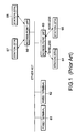
- FIG. 1 illustrates an example of configuration of a network in which such a wireless LAN is connected to wired LANs.
- APs 63 and 66 are provided on wired LANs of an Ethernet or the like having a plurality of fixed terminals 61 and 62.
- fixed terminals are connected to each other with a wired LAN, and connection between the fixed terminals and STAs and mutual connection between the STAs are accomplished with wireless LANs, to transmit data.
- each AP usually manages the synchronization of communication among the plurality of STAs connected to it and controls information for identifying the STAs to be connected.
- the AP referencing data transmitted over a wired LAN, judges whether or not they are data to be transmitted to any STA connected to the AP and, if it judges that they are, delivers them to the wireless section. This judgment is known as filtering. Methods of filtering by APs are disclosed in the Japanese Patent Application Laid-open No. Hei 8-274804 and elsewhere, and they are now effectively used for practical purposes.
- Another available network form for wireless LANs consists solely of STAs, commonly known as an ad hoc network. This type of network is typically used for temporary application, for instance in the direct connection of terminals brought in by members participating in a meeting in a conference room.
- FIG. 2 is a block diagram illustrating an example of configuration of an ad hoc network.
- the network system illustrated therein communicates by transmitting wireless frames among a plurality of STAs 71, 72 and 73.
- Both these network forms are standardized as wireless LANs.
- the network illustrated in FIG. 1 is defined as an integration type network, while the ad hoc network shown in FIG. 2 is defined as an independent basic service set (IBSS) prescribed by IEEE802.11 "Wireless LAN Medium Access Control (MAC) and Physical Layer (PHY) specification".
- IBSS independent basic service set
- IEEE802.11 Wired LAN Medium Access Control
- PHY Physical Layer
- the synchronization method, communication method and the like for each are expressly specified (see ISO/IEC DIS 8802-11 IEEE P802.11/D10, 14 Jan. 1999, pp. 46-59 and 125-127).
- APs centrally manage synchronization by periodically transmitting information on synchronization.
- the IBSS is incapable of centralized management of synchronization as it consists solely of STAs. For this reason it uses a synchronization frame known as a Beacon frame, and all the STAs are equally entitled to transmit this Beacon frame and synchronization is thereby managed in a decentralized manner.
- a Beacon frame contains the following items of information: a baseband data system and a carrier modulation system for physical layers, a time stamp at the time of transmitting the Beacon frame utilized as synchronization information, the Beacon interval and so forth.
- Each STA manages the transmission timing of the Beacon frame so that Beacon frames may not run into collision on a wireless line but can be normally received. More specifically, each STA, after waiting for (delaying by) a random length of time according to uniform distributions independent of each other at the starting time of a Beacon interval, delivers the Beacon frame.
- Each STA if no Beacon frame is received from any other STA during the waiting period, delivers for itself a Beacon frame as scheduled. This enables each STA to achieve synchronization in an independent decentralized manner. This method is standardized as a random back-off algorithm.
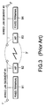
- FIG. 3 illustrates such a network form.
- the system shown in FIG. 3 has a wired LAN segment #1 having fixed terminals 81 and so on and a segment #2 having fixed terminals 84 and so on as physically distant wired LANs, and they are respectively provided with access points AP82 and 83 to constitute a bridge between the wired section and the wireless section and thereby connect the wired LANs with the wireless LAN 3'
- a bridge between the buildings can be established by installing APs capable of long-distance communication in the plurality of buildings and having the APs performing wireless communication between them, and a LAN system in which a plurality of independent wired LANs can form a single common domain is thereby realized.
- each AP has a transmitter address TA and a receiver address RA and each fixed terminal has a source address SA and a destination address DA, or a total of four different kinds of addresses, which poses the problem that such prior art methods of filtering whereby the frames supplied by fixed terminals are either connected or discarded between wired sections and wireless sections or address processing in APs cannot be applied.
- An object of the present invention is to provide a method for inter-LAN connection, an access point apparatus and a LAN system which make possible connection of wired LANs without having to set the synchronization mode of access points or newly providing its processing procedure.
- Another object of the invention is to provide a method for inter-LAN connection, an access point apparatus and a LAN system which make possible filtering among a plurality of wired LANs.
- each access point establishes synchronism by delivering a synchronization frame according to the provisions of an ad hoc network.
- Each access point has either a filtering table for storing authentication information on the source access points of frames received from a wireless LAN or a filtering table in which information on prior registrations is stored, references the table when a frame is received from the wireless LAN, and bridges the frame from the wireless LAN to a wired LAN in accordance with prescribed conditions.
- Each access point carries out learning by adding to or deleting from information on the prior registration as appropriate.
- access point apparatuses set an independent delay time for each access point apparatus according to the probability of uniform distribution, establish synchronism by delivering a synchronization frame, and transmit or receive frames according to each received or transmitted synchronization frame.
- Each access point apparatus has either a filtering table for storing authentication information on the source access points of frames received from a wireless LAN or a filtering table in which information on prior registrations is stored, references the table when a frame is received from the wireless LAN, and has a filtering means to bridge the frame from the wireless LAN to a wired LAN in accordance with prescribed conditions.
- each access point apparatus has a learning function to manage information stored in the filtering table by adding to or deleting it as appropriate.
- a LAN system connects a plurality of independent wired LANs, each equipped with a plurality of terminal apparatuses mutually connected by a LAN cable and one or more wireless access point apparatus or apparatuses with wireless access point apparatuses in a random back-off procedure so as to form a single common domain.
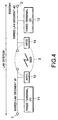
- FIG. 4 is a conceptual diagram of the method for inter-LAN connection, the access point apparatus and the LAN system embodying the invention.
- a configuration in which only two wired LANs are connected wirelessly.
- a wired LAN #1 having a fixed terminal (1) 11 and an access point AP (1) 12
- wired LAN #2 having a fixed terminal (2) 13 and an access point AP (2) 14 on a LAN cable are present, each in a separate region, and a wireless LAN is organized between the AP (1) 12 (hereinafter AP1) and the AP (2) 14 (hereinafter AP2).
- the wireless section between the AP1 and AP2 is composed of the aforementioned ad hoc network.
- an independent basic service set (IBSS) prescribed by IEEE802.11 "Wireless LAN Medium Access Control (MAC) and Physical Layer (PHY) specification" is adopted, and synchronization and communication between IBSSs on that basis make possible connection between the LANs.
- IBSS independent basic service set
- MAC Medium Access Control
- PHY Physical Layer
- ESSID extended service set identifier
- the AP1 and AP2 make possible mutual communication by bridging the frames transmitted over the wired LANs #1 and #2.
- the physical form of the network illustrated in FIG. 4, more specifically, is a case in which the wired LANs #1 and #2 (hereinafter LAN1 and LAN2, respectively) are present in different buildings, which are positioned on the opposite sides of a street.
- the AP1 and AP2 are installed to connect the LANs to effect wireless bridging and thereby make possible mutual connection between the wired LANs.
- wired LAN1 and wired LAN2 as they logically belong to the same network, permit additional connection of fixed terminals, removal of connected fixed terminals and shifting of any fixed terminal or terminals among the plurality of wired LANs. Description follows on the establishment of synchronism, the filtering table composition of each AP, filtering operation and so forth to realize the above-described functions of this embodiment.
- the AP1 and AP2 are configured to maintain synchronism independently and in a decentralized manner by constituting IBSSs prescribed by IEEE 802.11.
- each station in order to maintain the synchronism of the mutually delivered frames, transmits a Beacon frame as a synchronization frame for the control purposes including necessary control information.
- the Beacon frame are stored, in addition to a baseband data system and a carrier modulation system for physical layers, a time stamp at the time of transmitting the Beacon frame as synchronization information, the Beacon interval and so forth.
- Each station determines its own timing for transmitting or receiving a Beacon frame with reference to the timing of transmitting or receiving the delivered Beacon frame, and carries out communication on that basis.
- This synchronization method uses a random back-off algorithm.
- Each station as it transmits and receives the Beacon frame at the Beacon intervals, which are synchronized among the different stations, manages the transmission timing of the Beacon frame so that Beacon frames may not run into collision on the wireless line but can be normally received.
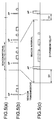
- FIG. 5 is a time chart outlining the synchronizing operation according to the random back-off algorithm in this embodiment.
- FIG. 5 (a) illustrates the Beacon interval, which is the basic information according to which individual APs establish synchronism in mutual communication.
- the Beacon interval is the information which serves as the reference for delivering a Beacon frame, and the individual APs share the Beacon interval information, i.e. the information on the absolute length between the starting point of one interval and that of the next.
- FIG. 5 (b) illustrates Beacon frames AP2, AP1 and AP1, ... actually delivered from the individual APs in the wireless section in a state in which each AP delivers a frame with reference to one or another of the aforementioned Beacon frames
- FIG. 5 (c) is a time chart in which those time lengths are expanded.
- each AP delivers a Beacon frame at random.
- Such a rule of Beacon frame delivery is realized at each AP, at the starting point of a Beacon interval, sets the delivery time so as to deliver a Beacon frame after waiting for (delaying by) a random length of time (D1) according to mutually independent uniform distributions and, if no Beacon frame is received from any other station at each timing, delivers a Beacon frame for itself as scheduled. Therefore, Beacon frame delivery by each station is so controlled that if, at the time it is scheduled to deliver a Beacon frame, a Beacon frame is received from another station, it refrain from delivering a Beacon frame.
- each Beacon frame is delivered at each Beacon interval, though in an extremely rare case a plurality of Beacon frames may be delivered at the same time if a plurality of APs have happened to set such delivery timings that each output a Beacon frame in the same waiting time (D1) according to the probability of each. Therefore, each AP can establish synchronism with reference to a Beacon frame delivered in this manner.
- each AP makes it possible to prevent collision of Beacon frames between APs and enables each station to establish synchronism according to algorithm and thereby to perform synchronizing operation.
- ESSID extended service set identifier
- FIG. 6 illustrates how a frame header is converted in the wired section and the wireless section, and this is an example of frame header conversion in which the fixed terminal 11 on the wired LAN1 in FIG. 6 delivers a frame to the fixed terminals 13 on the wired LAN 2.
- the frame format that is used is the frame format for communication between APs prescribed by IEEE 802.11.
- the MAC address of the fixed terminal 13 is inserted into the destination address (DA) field, and the MAC address of the fixed terminal 11 is inserted into the source address (SA) field.
- the receiver address (RA) field and the transmitter address (TA) field are added to the header of the wired LAN1.
- a broadcast address meaning that it is destined for every station is inserted into the transmitter address field.
- the MAC address of the AP1 is inserted into the MAC address of the AP1. It is supposed that a plurality of APs to receive frames of the wireless section be installed, and by inserting the broadcast address into the receiver address field the plurality of APs are enabled to receive the frames.
- FIG. 7 illustrates a filtering table held by an AP on a wired LAN.
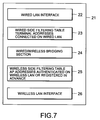
- a filtering table 21, matching the wired LAN has a wired LAN interface 22 and a wired side LAN filtering table 23 for storing the addresses of terminals connected on the wired LAN and, matching the wireless LAN, has a wireless LAN interface 26 and a wireless side filtering table 25 for storing AP addresses either authenticated or registered in advance, as will be explained later, on the wireless LAN. It further has a wired/wireless bridging section 24 for bridging a frame between wired and wireless sections.
- Each AP in order to bridge (transfer) a frame to be transmitted between the wired section and the wireless section selectively as to wired or wireless transmission, performs filtering control over the frame with reference to the wired side filtering table 22 and the wireless side filtering table 25.
- each AP stores the addresses of fixed terminals connected to the wired LAN under its control into the wired side filtering table 23 by its learning function according to the source address of the frame on the wired LAN and stores the authentication information and the like of the AP into the wireless side filtering table 25.
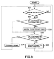
- FIG. 8 is a flow chart of a filtering operation which takes place when an AP receives a frame for bridging from a wired section to a wireless section.
- the AP when an AP receives a frame for bridging from a wired LAN to a wireless LAN (step S31), the AP first references the wired side filtering table 23 and judges whether or not the source address SA of the frame is contained in the wired side filtering table 23 (step S32) and, if it is not, adds the SA to the wired side filtering table 23 (step S33). Then, it again references the wired side filtering table 23 and judges whether the destination address DA of the frame is contained in the wired side filtering table 23 (step S34) and, if it is, discards the frame (step S36) or, if it is not, bridges the frame to the wireless side (step S35).
- steps S32 and S33 are steps at which the AP performs the function of learning the filtering table of the SA of the frame the AP has received from the wired LAN.
- the SAs of fixed terminals newly connected to the wired LAN or shifted from another wired LAN are also learned.
- filtering is performed to forbid the frame to be transferred to the DA present on the wired LAN to which the AP is connected from being bridged to the wireless side of the AP.
- FIG. 9 is a flow chart of a filtering operation which, when an AP receives a frame from a wireless section, is performed by the receiving AP.
- an AP When an AP receives a frame from the wireless side (step S41), it judges whether or not the RA of the received frame is a broadcast address (step S42) and, if the RA is not a broadcast address or the received frame is an unsuitable frame, discards the frame (step S50). Or if the RA is a broadcast address, it references the wireless side filtering table 25, and judges whether or not the TA of the received frame is authenticated as a transmitter address of the network (step S43). If the TA is not authenticated because, for instance the procedure of authentication which is supposed to follow the establishment of synchronism or the like is not completed yet, the receiving AP requests the AP having transmitted the frame to authenticate it (step S47).
- step S48 judges whether or not the transmitting AP has authenticated the TA (step S48); upon confirmation of the authentication of the TA, it stores the authentication into the wireless side filtering table 25 (S49); it bridges the received frame to the wired side (step S44); and it judges whether not the SA of the received frame is contained in the wired side filtering table 23 (step S46). If the SA is contained in the filtering table 23, the SA is deleted from the filtering table (step S46).
- Steps S45 and S46 in the flow chart of FIG. 9 provide the function of learning to delete, when the fixed terminal on the wired LAN to which the frame is to be bridged has been removed by shirting or otherwise, the address of that fixed terminal from the filtering table.
- the AP detects this change after bridging from the wireless section to the wired section, and deletes the registration of that SA already learned and stored in the filtering table of the AP.
- each AP achieves synchronization independently in a decentralized manner with a synchronization frame, there is no need to have a complex configuration in which different levels of priority are assigned to different APs, such as differentiating master and slave APs, and different operations are made possible for different synchronization modes, master and slave.
- This enables the hardware configuration to be simplified.
- each AP to be either master or slave, it is possible to connect a plurality of wired LANs with wireless LANs linking wireless APs and form a single common domain without having to organize a non-standard new procedure, such as a procedure for negotiations.
- filtering with authentication information in the wireless section can prevent any AP, fixed terminal or the like not registered in the authentication information from unauthorized entrance into the network.
- a plurality of wired LANs connected by the wireless LAN can be organized into a network in which address information in the filtering tables is constantly updated and address management is rationally carried out even if terminals are shifted between wired LANs.
- FIG. 10 shows a processing flow in the configuration in which the above-described request for authentication if replaced by prior registration.
- the AP receives a frame from the wireless side (step S51) and, if the RA of the received frame is a broadcast address, references the wireless side filtering table 25 to judge whether or not the TA is registered in advance (step S53). If it is already registered, the frame is bridged to the wired side (step S54) or, if it is not, the frame is discarded (step S57). In this case, it is preferable to have a configuration in which setting of prior registration is requested or processing information on frame discarding is displayed in some way or other.
- the prior registration can be so configured as to additionally register or delete the pertinent information. It is also possible to so configure the prior registration as to register the MAC address of the AP whose connection is to be permitted into the wireless side filtering table 25. Another conceivable configuration is to allow, in such a procedure as authentication at the time of establishing IBSS between APs, checking of whether or not the MAC address of the other AP is registered.
- a frame received from a wired LAN is to be transmitted to a wireless LAN
- a broadcast address is used as the receiver address of the wireless frame header, but an intrinsic address of the receiver AP can be used instead of a broadcast address where only one receiver AP can be specified for coverage.
- the wireless side filtering table can as well be so configured as to add, if authentication is successfully done in response to an authentication request to the transmitter AP, the pertinent transmitter address to the already stored authenticated information or as not to permit addition.
- such setting can be done in advance either for all the transmitter APs or individually for each transmitter AP.
- filtering with prior registration information in the wireless section can prevent APs or fixed terminals not registered in advance from effecting unauthorized entrance into the network.
- the invention by providing one or more wireless access point apparatus or apparatuses for each of a plurality of independent wired LANs and connecting the wireless accessing apparatuses to one another in a random back-off procedure, it is possible to provide a LAN system permitting connection of a plurality of independent wired LANs so as to form a single common domain in accordance with a standardized procedure.
Landscapes
- Engineering & Computer Science (AREA)
- Computer Security & Cryptography (AREA)
- Computer Networks & Wireless Communication (AREA)
- Signal Processing (AREA)
- Computer Hardware Design (AREA)
- Computing Systems (AREA)
- General Engineering & Computer Science (AREA)
- Mobile Radio Communication Systems (AREA)
- Small-Scale Networks (AREA)
Abstract
Description
Claims (20)
- A method for inter-LAN connection whereby a plurality of wired LANs to which fixed terminals are connected are connected to a wireless LAN via an access point on each wired LAN, andeach access point establishes synchronism by delivering a synchronization frame after predetermined delay time on condition that no synchronization frame is received from any other access point.
- A method for inter-LAN connection, as claimed in Claim 1, whereby:the procedure in which each access point delivers a synchronization frame conforms to the provisions of an ad hoc network.
- A method for inter-LAN connection whereby a plurality of wired LANs to which fixed terminals are connected are connected to a wireless LAN via an access point on each wired LAN,each access point has a filtering table for storing authentication information of the access points of the sources of frames received from the wireless LAN,references said filtering table for any frame received from the wireless LAN and, if it is authenticated, bridges the frame from the wireless LAN to the wired LAN or, if it is not authenticated, discards the frame.
- A method for inter-LAN connection whereby a plurality of wired LANs to which fixed terminals are connected are connected to a wireless LAN via an access point on each wired LAN,each access point has a filtering table for storing authentication information of the access points of the sources of frames received from the wireless LAN,references said filtering table for any frame received from the wireless LAN and, if it is authenticated, bridges the frame from the wireless LAN to the wired LAN or, if it is not authenticated, bridges the frame from the wireless LAN to the wired LAN after having acquired authentication by the access point having delivered the frame.
- A method for inter-LAN connection, as claimed in Claim 4, whereby:each access point stores a frame received from the wireless LAN into said filtering table if authentication is newly acquired from the access point having delivered the frame.
- A method for inter-LAN connection whereby a plurality of wired LANs to which fixed terminals are connected are connected to a wireless LAN via an access point on each wired LAN,each access point has a filtering table for storing information on the prior registration of the access points of the sources of frames received from the wireless LAN,references said filtering table for frames received from the wireless LAN and bridges any frame delivered from any access point registered in advance to the wired side LAN.
- A method for inter-LAN connection, as claimed in Claim 6, whereby:each access point stores or deletes as appropriate information on prior registration of the access points of the sources of frames to be stored in said filtering table.
- A method for inter-LAN connection, as claimed in Claim 3, whereby:each access point stores into said filtering table the address of fixed terminals on the wired LANs on the basis of the source addresses of frames received from the wired LAN side, and deletes, on the basis of the source address of any frame received from the wireless LAN side and bridged to the wired LAN side, the pertinent stored address.
- A method for inter-LAN connection, as claimed in Claim 4, whereby:each access point stores into said filtering table the address of fixed terminals on the wired LANs on the basis of the source addresses of frames received from the wired LAN side, and deletes, on the basis of the source address of any frame received from the wireless LAN side and bridged to the wired LAN side, the pertinent stored address.
- A method for inter-LAN connection, as claimed in Claim 6, whereby:each access point stores into said filtering table the address of fixed terminals on the wired LANs on the basis of the source address of frames received from the wired LAN side, and deletes, on the basis of the source address of any frame received from the wireless LAN side and bridged to the wired LAN side, the pertinent stored address.
- An access point apparatus for use in inter-LAN connection whereby a plurality of wired LANs to which fixed terminals are connected are connected to a wireless LAN via an access point on each wired LAN,said access point apparatusestablishes synchronism by delivering a synchronization frame after predetermined delay time on condition that no synchronization frame is received from any other access point, and transmits or receives frame with reference to said synchronization frame that has been received or transmitted.
- An access point apparatus for use in inter-LAN connection whereby a plurality of wired LANs to which fixed terminals are connected are connected to a wireless LAN via an access point on each wired LAN,said access point apparatushas a filtering table for storing authentication information of the access points of the sources of frames received from the wireless LAN, and a filtering unit for referencing said filtering table for any frame received from the wireless LAN and, if it is authenticated, bridging the frame from the wireless LAN to the wired LAN or, if it is not authenticated, discarding the frame.
- An access point apparatus for use in inter-LAN connection whereby a plurality of wired LANs to which fixed terminals are connected are connected to a wireless LAN via an access point on each wired LAN,said access point apparatushas a filtering table for storing authentication information of the access points of the sources of frames received from the wireless LAN, and a filtering unit for referencing said filtering table for any frame received from the wireless LAN and, if it is authenticated, bridging the frame from the wireless LAN to the wired LAN or, if it is not authenticated, bridging the frame from the wireless LAN to the wired LAN after having acquired authentication by the access point having delivered the frame.
- An access point apparatus, as claimed in Claim 13, wherein:said access point apparatusstores a frame received from the wireless LAN into said filtering table if authentication is newly acquired from the access point having delivered the frame.
- An access point apparatus for use in inter-LAN connection whereby a plurality of wired LANs to which fixed terminals are connected are connected to a wireless LAN via an access point on each wired LAN,said access point apparatushas a filtering table for storing prior registration information of the access points of the sources of frames received from the wireless LAN, and a filtering unit for referencing said filtering table for frames received from the wireless LAN and bridging any frame delivered from any access point registered in advance to the wired side LAN.
- An access point apparatus, as claimed in Claim 15, wherein:said access point apparatusstores or deletes as appropriate information on prior registration of the access points of the sources of frames to be stored in said filtering table.
- An access point apparatus, as claimed in Claim 12, wherein:said access point apparatusstores into said filtering table the address of fixed terminals on the wired LANs on the basis of the source addresses of frames received from the wired LAN side, and deletes, on the basis of the source address of any frame received from the wireless LAN side and bridged to the wired LAN side, the pertinent stored address.
- An access point apparatus, as claimed in Claim 13, wherein:said access point apparatusstores into said filtering table the address of fixed terminals on the wired LANs on the basis of the source addresses of frames received from the wired LAN side, and deletes, on the basis of the source address of any frame received from the wireless LAN side and bridged to the wired LAN side, the pertinent stored address.
- An access point apparatus, as claimed in Claim 15, wherein:said access point apparatusstores into said filtering table the address of fixed terminals on the wired LANs on the basis of the source addresses of frames received from the wired LAN side, and deletes, on the basis of the source address of any frame received from the wireless LAN side and bridged to the wired LAN side, the pertinent stored address.
- A LAN system having a plurality of independent wired LANs, each equipped with a plurality of terminal apparatuses mutually connected by a LAN cable and one or more wireless access point apparatus or apparatuses, wherein each of said wireless access point apparatuses establishes mutual connection with other one or more wireless access point apparatus or apparatuses in a random back-off procedure so as to form a single common domain among a plurality of independent wired LANs.
Applications Claiming Priority (2)
| Application Number | Priority Date | Filing Date | Title |
|---|---|---|---|
| JP16888699A JP3412687B2 (en) | 1999-06-15 | 1999-06-15 | LAN connection method, access point device and LAN system |
| JP16888699 | 1999-06-15 |
Publications (2)
| Publication Number | Publication Date |
|---|---|
| EP1061694A2 true EP1061694A2 (en) | 2000-12-20 |
| EP1061694A3 EP1061694A3 (en) | 2004-01-02 |
Family
ID=15876399
Family Applications (1)
| Application Number | Title | Priority Date | Filing Date |
|---|---|---|---|
| EP20000112707 Withdrawn EP1061694A3 (en) | 1999-06-15 | 2000-06-15 | Inter-lan connection method access point apparatus and lan system |
Country Status (2)
| Country | Link |
|---|---|
| EP (1) | EP1061694A3 (en) |
| JP (1) | JP3412687B2 (en) |
Cited By (14)
| Publication number | Priority date | Publication date | Assignee | Title |
|---|---|---|---|---|
| WO2005041487A1 (en) | 2003-10-24 | 2005-05-06 | Sony Corporation | Radio communication system, radio communication apparatus, radio communication method, and computer program |
| CN1300973C (en) * | 2003-03-13 | 2007-02-14 | 三星电子株式会社 | Re-synchronizing method in wireless specific network environment |
| US7302257B2 (en) | 2002-07-08 | 2007-11-27 | Nec Corporation | Wireless access control method and wireless access system |
| GB2455074A (en) * | 2007-11-26 | 2009-06-03 | Tesco Stores Ltd | Wireless Network Access Points which exchange management data over air interfaces and other data over wired interconnections |
| CN100555964C (en) * | 2003-02-03 | 2009-10-28 | 索尼株式会社 | Communication method, communication device and computer program |
| CN101018171B (en) * | 2003-10-24 | 2011-03-23 | 索尼株式会社 | Radio communication system, radio communication apparatus, radio communication method, and program |
| US8050241B2 (en) | 2006-11-30 | 2011-11-01 | Research In Motion Limited | Determining identifiers for wireless networks |
| EP1626529A4 (en) * | 2003-05-16 | 2011-12-14 | Sony Corp | RADIO COMMUNICATION SYSTEM, APPARATUS AND METHOD, AND COMPUTER PROGRAM |
| US8295817B2 (en) | 2003-01-23 | 2012-10-23 | Research In Motion Limited | Methods and apparatus for re-establishing communication for wireless communication for a wireless communication device after a communication loss in a wireless communication network |
| US8644177B2 (en) | 2010-12-16 | 2014-02-04 | Blackberry Limited | Methods and apparatus for use in controlling data traffic for a wireless mobile terminal using a wireless access point (AP) |
| US8913600B2 (en) | 2003-01-07 | 2014-12-16 | Sony Corporation | Wireless communication apparatus, system, and device communicating with another wireless communication apparatus, system, and device in an autonomous distributed network without a designated control station and method thereof |
| US9148781B2 (en) | 2011-07-28 | 2015-09-29 | Hewlett-Packard Development Company, L.P. | Wireless transmission of data packets based on client associations |
| EP2466934A4 (en) * | 2009-09-17 | 2017-08-30 | ZTE Corporation | Method and system for message transmission control, method and system for register/update |
| US9883487B2 (en) | 2008-05-09 | 2018-01-30 | Huawei Technologies Co., Ltd. | Scalable WLAN gateway |
Families Citing this family (8)
| Publication number | Priority date | Publication date | Assignee | Title |
|---|---|---|---|---|
| JP3983994B2 (en) * | 2001-04-13 | 2007-09-26 | 株式会社日立製作所 | Wireless transmission system and transmission apparatus therefor |
| CN100444545C (en) | 2001-11-29 | 2008-12-17 | 西门子公司 | Use the public key pair in the terminal equipment to allow network operators and business partners to authenticate and authorize telecom users |
| JP4577019B2 (en) * | 2004-03-04 | 2010-11-10 | ソニー株式会社 | Wireless communication system, wireless communication apparatus, wireless communication method, and computer program |
| JP5343956B2 (en) * | 2004-11-01 | 2013-11-13 | 横河電機株式会社 | Field device signal transmission method, field device, wireless module, system |
| CN101123465B (en) * | 2006-08-09 | 2012-07-04 | 上海贝尔阿尔卡特股份有限公司 | Method and device for synchronization of network devices in wireless communication system |
| JP2009033274A (en) | 2007-07-25 | 2009-02-12 | Nec Access Technica Ltd | Wireless LAN slave unit, wireless LAN network, and MAC address relearning method used therefor |
| JP5491633B2 (en) * | 2009-09-28 | 2014-05-14 | 華為技術有限公司 | Communication device, operation method and software |
| JP2014143697A (en) * | 2014-02-27 | 2014-08-07 | Huawei Technologies Co Ltd | Scalable WLAN gateway |
Family Cites Families (3)
| Publication number | Priority date | Publication date | Assignee | Title |
|---|---|---|---|---|
| EP0740873B1 (en) * | 1993-11-04 | 2005-12-21 | Norand Corporation | A communication network providing wireless and hard-wired dynamic routing |
| CA2129199C (en) * | 1994-07-29 | 1999-07-20 | Roger Y.M. Cheung | Method and apparatus for bridging wireless lan to a wired lan |
| JP2944531B2 (en) * | 1996-09-12 | 1999-09-06 | 日本電気通信システム株式会社 | LAN connection device |
-
1999
- 1999-06-15 JP JP16888699A patent/JP3412687B2/en not_active Expired - Fee Related
-
2000
- 2000-06-15 EP EP20000112707 patent/EP1061694A3/en not_active Withdrawn
Cited By (35)
| Publication number | Priority date | Publication date | Assignee | Title |
|---|---|---|---|---|
| US7302257B2 (en) | 2002-07-08 | 2007-11-27 | Nec Corporation | Wireless access control method and wireless access system |
| US8913600B2 (en) | 2003-01-07 | 2014-12-16 | Sony Corporation | Wireless communication apparatus, system, and device communicating with another wireless communication apparatus, system, and device in an autonomous distributed network without a designated control station and method thereof |
| US8295817B2 (en) | 2003-01-23 | 2012-10-23 | Research In Motion Limited | Methods and apparatus for re-establishing communication for wireless communication for a wireless communication device after a communication loss in a wireless communication network |
| US9655115B2 (en) | 2003-02-03 | 2017-05-16 | Sony Corporation | Communication method, communication device, and computer program |
| CN100555964C (en) * | 2003-02-03 | 2009-10-28 | 索尼株式会社 | Communication method, communication device and computer program |
| US10028271B2 (en) | 2003-02-03 | 2018-07-17 | Sony Corporation | Communication method, communication device, and computer program |
| US11323999B2 (en) | 2003-02-03 | 2022-05-03 | Sony Corporation | Communication method, communication device, and computer program |
| EP1592176A4 (en) * | 2003-02-03 | 2011-03-02 | Sony Corp | METHOD AND DEVICE FOR COMMUNICATION, AND SOFTWARE |
| US8837448B2 (en) | 2003-02-03 | 2014-09-16 | Sony Corporation | Communication method, communication device, and computer program |
| US8761072B2 (en) | 2003-02-03 | 2014-06-24 | Sony Corporation | Communication method, communication device, and computer program |
| US8670713B2 (en) | 2003-02-03 | 2014-03-11 | Sony Corporation | Communication method, communication device, and computer program |
| US8099049B2 (en) | 2003-02-03 | 2012-01-17 | Sony Corporation | Communication method, communication device, and computer program |
| CN101668345B (en) * | 2003-02-03 | 2013-07-31 | 索尼株式会社 | Communication apparatus |
| CN1300973C (en) * | 2003-03-13 | 2007-02-14 | 三星电子株式会社 | Re-synchronizing method in wireless specific network environment |
| EP1626529A4 (en) * | 2003-05-16 | 2011-12-14 | Sony Corp | RADIO COMMUNICATION SYSTEM, APPARATUS AND METHOD, AND COMPUTER PROGRAM |
| US8400993B2 (en) | 2003-10-24 | 2013-03-19 | Sony Corporation | Radio communication system, radio communication apparatus, radio communication method, and computer program |
| US9185698B2 (en) | 2003-10-24 | 2015-11-10 | Sony Corporation | Radio communication system, radio communication apparatus, radio communication method, and computer program |
| US8199737B2 (en) | 2003-10-24 | 2012-06-12 | Sony Corporation | Radio communication system, radio communication apparatus, radio communication method, and computer program |
| US10660087B2 (en) | 2003-10-24 | 2020-05-19 | Sony Corporation | Radio communication system, radio communication apparatus, radio communication method, and computer program |
| EP1677456A4 (en) * | 2003-10-24 | 2010-06-02 | Sony Corp | RADIO COMMUNICATION SYSTEM, RADIO COMMUNICATION APPARATUS, RADIO COMMUNICATION METHOD, AND COMPUTER PROGRAM |
| US7995548B2 (en) | 2003-10-24 | 2011-08-09 | Sony Corporation | Radio communication system, radio communication apparatus, radio communication method, and computer program |
| KR101031726B1 (en) * | 2003-10-24 | 2011-04-29 | 소니 주식회사 | Wireless communication device |
| CN101018171B (en) * | 2003-10-24 | 2011-03-23 | 索尼株式会社 | Radio communication system, radio communication apparatus, radio communication method, and program |
| EP3310006A1 (en) * | 2003-10-24 | 2018-04-18 | Sony Corporation | Reducing beacon collision probability |
| WO2005041487A1 (en) | 2003-10-24 | 2005-05-06 | Sony Corporation | Radio communication system, radio communication apparatus, radio communication method, and computer program |
| EP2197158A3 (en) * | 2003-10-24 | 2010-10-06 | Sony Corporation | Reducing beacon collision probability |
| US8050241B2 (en) | 2006-11-30 | 2011-11-01 | Research In Motion Limited | Determining identifiers for wireless networks |
| GB2455074A (en) * | 2007-11-26 | 2009-06-03 | Tesco Stores Ltd | Wireless Network Access Points which exchange management data over air interfaces and other data over wired interconnections |
| US9883487B2 (en) | 2008-05-09 | 2018-01-30 | Huawei Technologies Co., Ltd. | Scalable WLAN gateway |
| US10327228B2 (en) | 2008-05-09 | 2019-06-18 | Huawei Technologies Co., Ltd. | Scalable WLAN gateway |
| US10952073B2 (en) | 2008-05-09 | 2021-03-16 | Huawei Technologies Co., Ltd. | Scalable WLAN gateway |
| US11457358B2 (en) | 2008-05-09 | 2022-09-27 | Huawei Technologies Co., Ltd. | Scalable WLAN gateway |
| EP2466934A4 (en) * | 2009-09-17 | 2017-08-30 | ZTE Corporation | Method and system for message transmission control, method and system for register/update |
| US8644177B2 (en) | 2010-12-16 | 2014-02-04 | Blackberry Limited | Methods and apparatus for use in controlling data traffic for a wireless mobile terminal using a wireless access point (AP) |
| US9148781B2 (en) | 2011-07-28 | 2015-09-29 | Hewlett-Packard Development Company, L.P. | Wireless transmission of data packets based on client associations |
Also Published As
| Publication number | Publication date |
|---|---|
| JP2000358059A (en) | 2000-12-26 |
| EP1061694A3 (en) | 2004-01-02 |
| JP3412687B2 (en) | 2003-06-03 |
Similar Documents
| Publication | Publication Date | Title |
|---|---|---|
| EP1061694A2 (en) | Inter-lan connection method access point apparatus and lan system | |
| US7856008B2 (en) | Synchronizing channel sharing with neighboring networks | |
| KR100630355B1 (en) | Apparatus and Method for Providing Frame Bridge in Wireless LAN | |
| US7821964B2 (en) | Methods and systems for network coordination | |
| US6967944B2 (en) | Increasing link capacity via concurrent transmissions in centralized wireless LANs | |
| JP4219809B2 (en) | Network with several sub-networks | |
| US6345043B1 (en) | Access scheme for a wireless LAN station to connect an access point | |
| US20020194384A1 (en) | Ad hov networks comprinsing a plurlity of terminals for determining terminals as controllers of sub-networks | |
| EP1533950A1 (en) | Method for connecting a mobile terminal to a wireless communication system, wireless communication system and mobile terminal for a wireless communication system | |
| CN104244350A (en) | Distributed seamless roaming in wireless networks | |
| US8605596B2 (en) | Medium access for de-centralized wireless network | |
| JP2003110583A (en) | Data transmission method and propagation delay complement method in one-to-many data communication network | |
| KR20110053257A (en) | Proxy Mechanisms for Meshed Networks | |
| US8068467B2 (en) | Multi-tier WLAN and method for propagating beacons in a multi-tier WLAN thereof | |
| WO2015179076A1 (en) | Method and apparatus for supporting sub networks in a moca network | |
| JP2002158677A (en) | Reconfiguration of ad hoc networks | |
| US20060014492A1 (en) | Ieee 802.11e mac signaling to support schedule qos | |
| US7295530B2 (en) | System and method for communication connection via heterogeneous networks | |
| KR101246774B1 (en) | Method and apparatus for transmitting/receiving a signal in a wireless local network mesh communication system | |
| CN103501354A (en) | Method and device for obtaining base station self-starting configuration parameters | |
| US7822422B2 (en) | Wireless communication system for improved transmission priority control | |
| JP2002314575A (en) | Network having a plurality of sub-networks that can be connected through a bridge terminal | |
| CN109076498B (en) | A method for forming a central access point AP cluster and an access point | |
| Vergados et al. | Synchronization of multiple access points in the IEEE 802.11 point coordination function | |
| US20210076294A1 (en) | Techniques and architectures for coordinated scanning in a mesh cluster with beacon synchronization |
Legal Events
| Date | Code | Title | Description |
|---|---|---|---|
| PUAI | Public reference made under article 153(3) epc to a published international application that has entered the european phase |
Free format text: ORIGINAL CODE: 0009012 |
|
| AK | Designated contracting states |
Kind code of ref document: A2 Designated state(s): AT BE CH CY DE DK ES FI FR GB GR IE IT LI LU MC NL PT SE |
|
| AX | Request for extension of the european patent |
Free format text: AL;LT;LV;MK;RO;SI |
|
| PUAL | Search report despatched |
Free format text: ORIGINAL CODE: 0009013 |
|
| AK | Designated contracting states |
Kind code of ref document: A3 Designated state(s): AT BE CH CY DE DK ES FI FR GB GR IE IT LI LU MC NL PT SE |
|
| AX | Request for extension of the european patent |
Extension state: AL LT LV MK RO SI |
|
| 17P | Request for examination filed |
Effective date: 20040405 |
|
| 17Q | First examination report despatched |
Effective date: 20040810 |
|
| AKX | Designation fees paid |
Designated state(s): DE NL SE |
|
| STAA | Information on the status of an ep patent application or granted ep patent |
Free format text: STATUS: THE APPLICATION IS DEEMED TO BE WITHDRAWN |
|
| 18D | Application deemed to be withdrawn |
Effective date: 20041221 |