EP1061655A2 - An audio system conducting digital signal processing, a control method thereof, a recording media on which the control method is recorded - Google Patents
An audio system conducting digital signal processing, a control method thereof, a recording media on which the control method is recorded Download PDFInfo
- Publication number
- EP1061655A2 EP1061655A2 EP00111948A EP00111948A EP1061655A2 EP 1061655 A2 EP1061655 A2 EP 1061655A2 EP 00111948 A EP00111948 A EP 00111948A EP 00111948 A EP00111948 A EP 00111948A EP 1061655 A2 EP1061655 A2 EP 1061655A2
- Authority
- EP
- European Patent Office
- Prior art keywords
- parameter
- value
- audio system
- image data
- effect
- Prior art date
- Legal status (The legal status is an assumption and is not a legal conclusion. Google has not performed a legal analysis and makes no representation as to the accuracy of the status listed.)
- Granted
Links
- 238000000034 method Methods 0.000 title claims description 17
- 230000000694 effects Effects 0.000 claims abstract description 70
- 230000010365 information processing Effects 0.000 claims 1
- 239000000126 substance Substances 0.000 abstract 1
- 230000005236 sound signal Effects 0.000 description 24
- 238000010586 diagram Methods 0.000 description 6
- 230000006870 function Effects 0.000 description 5
- 241001050985 Disco Species 0.000 description 1
- 230000005540 biological transmission Effects 0.000 description 1
- 230000015556 catabolic process Effects 0.000 description 1
- 238000010276 construction Methods 0.000 description 1
- 230000003247 decreasing effect Effects 0.000 description 1
- 238000006731 degradation reaction Methods 0.000 description 1
- 239000004973 liquid crystal related substance Substances 0.000 description 1
- 238000004020 luminiscence type Methods 0.000 description 1
- 238000004519 manufacturing process Methods 0.000 description 1
- 239000011159 matrix material Substances 0.000 description 1
- 230000004044 response Effects 0.000 description 1
- 239000011435 rock Substances 0.000 description 1
Images



Classifications
-
- G—PHYSICS
- G11—INFORMATION STORAGE
- G11B—INFORMATION STORAGE BASED ON RELATIVE MOVEMENT BETWEEN RECORD CARRIER AND TRANSDUCER
- G11B27/00—Editing; Indexing; Addressing; Timing or synchronising; Monitoring; Measuring tape travel
- G11B27/02—Editing, e.g. varying the order of information signals recorded on, or reproduced from, record carriers
- G11B27/022—Electronic editing of analogue information signals, e.g. audio or video signals
- G11B27/028—Electronic editing of analogue information signals, e.g. audio or video signals with computer assistance
-
- G—PHYSICS
- G11—INFORMATION STORAGE
- G11B—INFORMATION STORAGE BASED ON RELATIVE MOVEMENT BETWEEN RECORD CARRIER AND TRANSDUCER
- G11B27/00—Editing; Indexing; Addressing; Timing or synchronising; Monitoring; Measuring tape travel
- G11B27/02—Editing, e.g. varying the order of information signals recorded on, or reproduced from, record carriers
- G11B27/031—Electronic editing of digitised analogue information signals, e.g. audio or video signals
Definitions
- the present invention relates to an audio system, a control method thereof, and a recording media on which a program of the method is recorded, and in particular, to an audio system capable of changing an acoustic effect or a sound effect using a graphical user interface (GUI) and a digital signal processor (DSP), a control method of the audio system, and a recording media on which a program of the method is recorded.
- GUI graphical user interface
- DSP digital signal processor
- Fig. 13 shows a block diagram an outline of an amplifier system as an example of a stand-alone audio system of the prior art.
- An external compact disk (CD) player supplies a digital audio signal or an analog audio signal to a CD player terminal T1.
- An external tuner inputs an analog audio signal to a tuner terminal T2.
- Other audio signals are fed to a first auxiliary terminal T3 and a second auxiliary terminal T4.
- An input selector SL is connected to the terminals T1 to T4.
- the selector SL includes a digital-to-analog (D/A) converter and an analog-to-digital (A/D) converter, which are not shown.
- An analog audio signal is delivered via the selector SL to an audio amplifier section AM.
- the amplifier section AM conducts a digital signal processing (DSP) for the received signal, amplifies the resultant audio signal, and then outputs the amplified signal to a speaker terminal Ts.
- DSP digital signal processing
- the terminal Ts is connected to a loudspeaker, not shown.
- a central processing unit (CPU) 150 controls the overall operation of the amplifier system AS.
- a read-only memory (ROM) 151 stores various programs for DSP, data for DSP, various control programs, and control data.
- a random access memory (RAM) 152 serves as a work area to temporarily store various data items.
- a display section 153 displays various information items such as a sound source being selected and a DSP mode.
- An operator panel 154 includes various types of operation keys.
- a bus 155 connects the input selector SL, the CPU 150, the ROM 151, the RAM 152, the display 153, and the operator panel 154 to each other.
- An external equipment inputs an analog audio signal or a digital audio signal via the selector SL to the amplifier section AM.
- the amplifier section AM amplifies the input signal and then outputs the amplified signal to the speaker terminal Ts.
- the display section 153 displays information of the selected sound source (e.g., a CD player) or the like.
- the input selector SL sequentially stores a digital signal obtained by converting an analog audio signal inputted from one of the terminals T1 to T4 or a digital audio signal therefrom in an RAM for DSP, not shown, in the audio amplifier section AM.
- the CPU 150 operates as a digital signal processor. Specifically, the CPU 150 reads from the ROM 151 a program corresponding to the selected DSP mode ("HALL”, “JAZZ”, “ROCK”, or “DISCO” mode) and conducts DSP for the digital audio signal stored in the DSP RAM.
- the amplifier section AM amplifies the analog audio signal resultant from the DSP and then outputs the amplified signal to the speaker terminal Ts.
- the speaker connected to the terminal Ts produces sound.
- the display section 153 displays information of the selected sound source (e.g., a CD player), the selected DSP mode (e.g., "JAZZ”), and the like.
- the selected sound source e.g., a CD player
- the selected DSP mode e.g., "JAZZ”
- a parameter value for each DSP mode is determined for the DSP parameter by the maker or manufacture of the system.
- an audio system comprising: image display for displaying a plurality of types of parameters to determine acoustic characteristics and displaying image data beforehand set respectively to values of the parameters, corresponding to values of the parameters; and operator display for displaying, for each of the parameter types, a parameter operator to indicate a value of a parameter.
- an audio system control method comprising: an image display step of displaying a plurality of types of parameters to determine acoustic characteristics, values of the parameters, and image data beforehand set respectively to the values of the parameters, corresponding to the values of the parameters and an operator display step of displaying, for each of the parameter types, a parameter operator to indicate a value of a parameter.
- a recording media for recording an audio system control program, wherein the program displays a plurality of types of parameters to determine acoustic characteristics, values of the parameters, and image data beforehand set respectively to the values of the parameters, corresponding to the values of the parameters and the program displays, for each of the parameter types, a parameter operator to indicate a value of a parameter.
- an audio system in which the user can visually recognize the effect of DSP parameter values on the acoustic effect and can easily change the parameter values, a control method thereof, and a recording media on which the method is recorded.
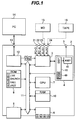
- Fig. 1 shows in a general block diagram of an embodiment of an audio system according to the present invention.
- the audio system 1 includes a receiver 2 and a personal computer 14.
- the receiver 2 includes a tuner section, not shown.
- the personal computer 14 is connected via a USB interface 12 to the receiver 2 to control the receiver 2. If desired, the user can expand the audio system 1 by connecting a mini-disk (MD) player 15 to a first auxiliary terminal 23, which will be described later, and/or a tape deck 16 to a second auxiliary terminal 24, which will be described later.
- MD mini-disk
- a digital audio signal from a sound card of the personal computer 14 is inputted to a digital audio signal terminal 21.
- An analog audio signal from a sound card of the computer 14 is fed to an analog audio signal terminal 22.
- a digital or analog audio signal from an external digital audio (recording) reproducing device such as an MD player is delivered to the first auxiliary terminal 23.
- An analog audio signal from an external digital audio (recording) reproducing device such as the tape deck 16 is delivered to the second auxiliary terminal 24.
- the signal connecting terminals 21 to 24 are connected to an input selector 3.
- An audio signal via USB, i.e., PC-U is inputted via a USB interface 12, which will be described later, to the selector 3.
- the selector 3 includes a D/A converter and an A/D converter.
- An audio amplifier 4 conducts digital signal processing for the analog audio signal received via the selector 3, amplifies the audio signal, and outputs the amplified signal to a speaker terminal 5.
- the terminal 5 is connected to a speaker.
- a digital signal processor (DSP) 18 in the audio amplifier 4 executes the digital signal processing (DSP).
- An RAM 49 in the DSP 18 functions as a work area in the audio amplifier 4 to temporarily store various data items.
- An operator panel 6 includes various operation keys.
- a CPU 7 supervises the overall operation of the receiver 2.
- a display 8 displays various information items such as a sound source being selected and a DSP mode.
- An ROM 9 stores various programs for DSP, data for DSP, various control programs, and control data.
- An RAM 10 serves as a work area to temporarily store various data.
- the USB interface 12 communicates signals via a USB terminal 13 with the personal computer 14. Specifically, the USB interface 12 transfers a control signal received from the computer 14 to a bus 11 and a control signal received from the bus 11 to the computer 14. On receiving an audio signal (PC-U) from the computer 14, the USB interface 12 sends the signal to the input selector 3.
- PC-U an audio signal
- the bus 11 connects the input selector 3, the audio amplifier 4, the operator panel 6, the CPU 7, the display 8, the ROM 9, the RAM 10, and the USB interface 12 to each other.
- the ROM 9 stores a program for the personal computer 14 to control the receiver 2.
- DPS parameter values set by the user can be freely registered to an area in the RAM 10.
- the parameter values registered are saved for a period by a memory backup system including batteries.
- the personal computer 14 controls the DSP mode change in the receiver 2. Moreover, the computer 14 changes each value of various types of parameters for each DSP mode, and each parameter values in the work area of the RAM 10.
- the personal computer 14 displays image data corresponding to a value inputted for each DSP parameter.
- the user can visually recognize an acoustic effect corresponding to each DSP mode.
- a program and graphic data to construct a GUI screen are supplied to the personal computer 14 via a recording media such as a CD-ROM.
- the DSP parameter is "Initial Delay".
- the "Initial Delay” parameter indicates, when a sound is produced, an interval of time between a first peak of sound pressure observed at a sound receiving point and a second peak thereof. Setting a longer interval between the first and second peaks indicates that the sound producer is further from the sound receiving point. Setting a shorter interval between the first and second peaks means that the sound producer is nearer to the sound receiving point.
- an image of the sound producer (e.g., a piano or the like) is displayed in a standard size as shown in Fig. 4a'.
- the image of the sound producer is displayed in a size smaller than the standard size as shown in Fig. 4a.
- the image of the sound producer is displayed in a size greater than the standard size as shown in Fig. 4a''.
- the image of the sound producer changes in size by altering the "Initial Delay" parameter as above.
- the user consequently can visually recognize effect of the change of the parameter value.
- the "Effect Trim” parameter is a parameter to adjust an overall level of acoustic or sound effect. Setting the “Effect Trim” parameter to a smaller value lowers the overall level of acoustic effect. Setting the “Effect Trim” parameter to a greater value increases the overall level of acoustic effect.
- the shade of the object around the image of the sound producer changes in gradation by altering the "Effect Trim” parameter value.
- the user hence can visually perceive effect of the change of the "Effect Trim” parameter value.
- the "Room Size” parameter is a parameter to set size of the listening room. Setting the "Room Size” parameter to a smaller value minimizes the space of the listening room. Setting the "Room Size” parameter to a greater value enlarges the room space.
- the space (for example, of a room) of the image is displayed in a standard size as shown in Fig. 4c'.
- the space displayed is smaller than the standard space as shown in Fig. 4c''.
- the space displayed is larger than the standard space as shown in Fig. 4c.
- the space displayed as the image changes in size by altering the "Room Size” parameter value. Therefore, the user can visually recognize effect of the change of the "Room Size” parameter value.
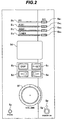
- Fig. 2 shows a front view of a front panel of the receiver 2.
- the front panel of the receiver 2 includes a plurality of switches partly constituting the operation panel 6.
- Selector switches 6a1 to 6a4 select a sound source.
- a DSP switch 6b indicates whether or not the DSP is operated.
- a preset switch 6c which can be set to on exclusively with respect to the DSP switch 6b, indicates whether or not preset station selection is desired to function when the tuner section is in use.
- a pair of up/down switches 6d and 6e function as a DSP mode selection switch.
- the preset switch 6c When the preset switch 6c is on, the switches 6d and 6e function as a station selection switch.
- a volume control 6f adjusts magnitude of sound volume.
- a power switch 6g turns power on/off.
- the front panel of the receiver 2 includes a headphone jack 5p to connect a headphone.
- the front panel of receiver 2 further includes display sections each constituting a part oh the display 8.
- a multifunctional display section 8d which includes a dot-matrix transmission liquid crystal display (LCD) with a backlight or a fluorescent luminescence (FL) display element, displays various information.
- a first indicator 8i1 turns on.
- a second indicator 8i2 turns on.
- a third indicator 8i3 turns on.
- a fourth indicator 8i4 turns on.
- a power indicator 8p turns on.
- Fig. 3 shows a front view of a rear panel of the receiver 2.
- the first auxiliary terminal 23 includes a digital audio auxiliary terminal 23 1 to receive a digital audio signal from an external digital (recording) reproducing device and an analog audio auxiliary terminal 23 2 to receive an analog audio signal from an external digital (recording) reproducing device.
- the rear panel further includes a USB terminal 13, antenna terminals (an FM antenna terminal, an AM antenna terminal, and a ground terminal), an analog audio output terminal, and a subwoofer output terminal.
- Fig. 5 shows an example of a DSP setting screen image displayed when the DSP parameters are set to the standard values.
- the DSP setting screen image includes a DSP parameter area 51 to display names of the DSP parameters, a parameter operator area 52 to set DSP parameter values in three stages, and an image picture 50 which changes according to the parameter setting values.
- Fig. 6 shows a DSP setting screen displayed when the "Initial Display” parameter is set to a value less than the standard value.
- the image picture 60 in Fig. 6 differs in size of the sound producer, i.e., a piano, from the image picture 50 displayed with the standard parameter value (Fig. 5).
- the piano 60a in the image picture 60 is larger than the piano 50a in the image picture 50.
- Fig. 7 shows a DSP setting screen image displayed when the "Initial Display” parameter is set to a value more than the standard value.
- the piano 70a in the image picture 70 is smaller in size than the piano 50a in the image picture 50.
- the user can visually recognize effect of the parameter.
- the value set to the "Initial Delay" parameter is more than the standard value, the effect obtained is almost the same as effect attained when the distance between the listener and the piano is increased.
- Fig. 8 shows a DSP setting screen image displayed when the "Effect Trim" parameter is set to a value less than the standard value.
- the image picture 80 in Fig. 8 and the image picture 50 displayed with the standard parameter value (Fig. 5) differ from each other in gradation or thickness/thinness of the shade of walls of the room.
- the shade of walls 80b in the image picture 80 is thinner than that of walls 50a in the image picture 50.
- the user can visually recognize that when the value set to the "Effect Trim” parameter is less than the standard value, a total level of acoustic or sound effect is decreased.
- Fig. 9 shows a DSP setting screen image displayed when the "Effect Trim" parameter is set to a value more than the standard value.
- the shade of walls 90b of the room in the image picture 90 is thicker than that of the walls 50a in the image picture 50.
- the user can visually recognize that when the value set to the "Effect Trim" parameter is more than the standard value, the total level of acoustic or sound effect is increased.
- Fig. 10 shows a DSP setting screen image displayed when the "Room Size" parameter is set to a value less than the standard value.
- the image picture 100 in Fig. 10 differs in size of space of the room from the image picture 50 displayed with the standard parameter value (Fig. 5).
- the space 100c of the room in the image picture 100 is smaller than the space 50c of the room in the image picture 50.
- the user can visually recognize effect obtained when the value set to the "Room Size" parameter is less than the standard value. Namely, the effect attained is substantially the same as effect obtained when the space of the room of the listener becomes smaller.
- Fig. 11 shows a DSP setting screen image displayed when the "Room Size" parameter is set to a value more than the standard value.
- the space 100c of the room in the image picture 110 is larger than the space 50c of the room in the image picture 50.
- the user can visually recognize that effect obtained when the value set to the "Room Size" parameter is more than the standard value is almost the same as effect attained when the space of the room of the listener becomes greater.
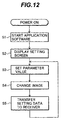
- the personal computer 14 is powered to start its operation, and then the computer 14 starts application software to set DSP parameters (step S1).
- the software displays, for example, the DSP setting screen image on a display of the computer 14 (step S2).
- the user selects in the screen a value of a DSP parameter to be changed (step S3).
- the software changes the image picture displayed on the DSP setting screen (step S4).
- the software changes the image picture 50 into the image picture 60 of Fig. 6.
- the user can therefore visually recognize that effect obtained when the value set to the "Initial Delay" parameter is less than the standard value is almost the same as effect attained when the listener is nearer to the piano as the sound source.
- the receiver 2 stores the values of parameters after the change in a work area of the RAM 10.
- the acoustic processing is thereafter executed according to the values of DSP parameters changed.
- the DSP setting screen of the embodiment displays three types of parameters, i.e., "Effect Trim”, “Room Size”, and "Initial Display”.
- the parameters to be changed in the DSP setting screen are not limited to the three types of parameters. Namely, other DSP parameters can also be treated in a similar fashion.
- the number of setting stages is not limited to three. That is, more than three stages may be employed, and the values may be continuously set, for example, by a slide bar.
- the gradation or thickness/thinness of the shade of walls and/or the ceiling of the room is changed in the image picture so that the viewer images effect of the change in the value "Effect Trim” parameter.
- patterns painted on walls and/or the ceiling of the room may be changed in the image picture for the viewer to image effect of the change in the value "Effect Trim” parameter.
Landscapes
- Engineering & Computer Science (AREA)
- Multimedia (AREA)
- General Engineering & Computer Science (AREA)
- Stereophonic System (AREA)
- Reverberation, Karaoke And Other Acoustics (AREA)
- User Interface Of Digital Computer (AREA)
- Control Of Amplification And Gain Control (AREA)
- Controls And Circuits For Display Device (AREA)
- Electrophonic Musical Instruments (AREA)
Abstract
Description
Claims (19)
- An audio system, comprising:image display for displaying a plurality of types of parameters to determine acoustic characteristics and displaying image data beforehand set respectively to values of the parameters, corresponding to values of the parameters; andoperator display for displaying, for each of the parameter types, a parameter operator to indicate a value of a parameter.
- An audio system according to claim 1, wherein the image display reads out image data corresponding to the value of the parameter indicated by the parameter operator and displays an image according to the image data.
- An audio system according to claim 1, wherein:the parameter operator indicates a value of a room characteristic parameter to determine an acoustic characteristic obtained by a size of a listening room; andthe image display displays image data in which the size of the room is imaged corresponding to the value indicated for the room characteristic parameter.
- An audio system according to claim 1, wherein:the parameter operator indicates a value of a distance characteristic parameter to determine an acoustic characteristic obtained by a distance between a listener and a sound source; andthe image display displays image data in which the distance is imaged corresponding to the value indicated for the distance characteristic parameter.
- An audio system according to claim 1 wherein:the parameter operator indicates, when assigning an effect to sound, a value of an effect quantity characteristic parameter to determine an acoustic characteristic obtained by a magnitude of the effect to be assigned; andthe image display displays image data in which the magnitude of the effect assigned to sound is imaged corresponding to the value indicated for the effect quantity characteristic parameter.
- An audio system according to claim 5, wherein the image display stores a shade corresponding to each value of the effect quantity characteristic parameter and sets the shade of the image data to a shade corresponding to the value indicated for the effect quantity characteristic parameter.
- An audio system according to claim 1, wherein the image display and the operator display include an information processing terminal including a display.
- An audio system control method, comprising:an image display step of displaying a plurality of types of parameters to determine acoustic characteristics, values of the parameters, and image data beforehand set respectively to the values of the parameters, corresponding to the values of the parameters andan operator display step of displaying, for each of the parameter types, a parameter operator to indicate a value of a parameter.
- An audio system control method according to claim 8, wherein the image display step includesreading out image data corresponding to the value of the parameter indicated by the parameter operator anddisplaying an image according to the image data.
- An audio system control method according to claim 8, wherein:the parameter operator displayed at the operator display step indicates a value of a room characteristic parameter to determine an acoustic characteristic concerning a size of a listening room; andthe image display step displays image data in which the size of the room is imaged corresponding to the value of the room characteristic parameter.
- An audio system control method according to claim 8, wherein:the parameter operator displayed at the operator display step indicates a value of a distance characteristic parameter to determine an acoustic characteristic concerning a distance between a listener and a sound source; andthe image display step displays image data in which the distance is imaged corresponding to the value of the distance characteristic parameter.
- An audio system control method according to claim 8, wherein:the parameter operator displayed at the operator display step indicates, when assigning an effect to sound, a value of an effect quantity characteristic parameter to determine an acoustic characteristic concerning a magnitude of the effect to be assigned; andthe image display step displays image data in which the magnitude of the effect assigned to sound is imaged corresponding to the value of the effect quantity characteristic parameter.
- An audio system control method according to claim 12, wherein the image display step sets the shade of the image data to a shade corresponding to the value indicated for the effect quantity characteristic parameter.
- A recording media for recording an audio system control program, whereinthe program displays a plurality of types of parameters to determine acoustic characteristics, values of the parameters, and image data beforehand set respectively to the values of the parameters, corresponding to the values of the parameters andthe program displays, for each of the parameter types, a parameter operator to indicate a value of a parameter.
- A recording media for recording an audio system control program according to claim 14, whereinwhen displaying the image, the control program reads out image data corresponding to the value of the parameter indicated by the parameter operator and displays an image according to the image data.
- A recording media for recording an audio system control program according to claim 14, whereinthe parameter operator indicates a value of a room characteristic parameter to determine an acoustic characteristic obtained by a size of a listening room; andwhen displaying the image, the program displays image data in which the size of the room is imaged corresponding to the value indicated for the room characteristic parameter.
- A recording media for recording an audio system control program according to claim 14, whereinthe parameter operator indicates a value of a distance characteristic parameter to determine an acoustic characteristic obtained by a distance between a listener and a sound source; andwhen displaying the image, the control program displays image data in which the distance is imaged corresponding to the value indicated for the distance characteristic parameter.
- A recording media for recording an audio system control program according to claim 14, whereinthe parameter operator indicates, when assigning an effect to sound, a value of an effect quantity characteristic parameter to determine an acoustic characteristic obtained by a magnitude of the effect to be assigned; andwhen displaying the image, the control program displays image data in which the magnitude of the effect assigned to sound is imaged corresponding to the value indicated for the effect quantity characteristic parameter.
- A recording media for recording an audio system control program according to claim 18, whereinwhen displaying the image, the control program sets the shade of the image data to a shade corresponding to the value indicated for the effect quantity characteristic parameter.
Applications Claiming Priority (2)
| Application Number | Priority Date | Filing Date | Title |
|---|---|---|---|
| JP16900099A JP3587088B2 (en) | 1999-06-15 | 1999-06-15 | Audio system, control method thereof, and recording medium |
| JP16900099 | 1999-06-15 |
Publications (3)
| Publication Number | Publication Date |
|---|---|
| EP1061655A2 true EP1061655A2 (en) | 2000-12-20 |
| EP1061655A3 EP1061655A3 (en) | 2003-05-07 |
| EP1061655B1 EP1061655B1 (en) | 2007-08-15 |
Family
ID=15878502
Family Applications (1)
| Application Number | Title | Priority Date | Filing Date |
|---|---|---|---|
| EP00111948A Expired - Lifetime EP1061655B1 (en) | 1999-06-15 | 2000-06-15 | An audio system conducting digital signal processing, and a control method thereof |
Country Status (4)
| Country | Link |
|---|---|
| US (1) | US7050869B1 (en) |
| EP (1) | EP1061655B1 (en) |
| JP (1) | JP3587088B2 (en) |
| DE (1) | DE60035922T2 (en) |
Cited By (1)
| Publication number | Priority date | Publication date | Assignee | Title |
|---|---|---|---|---|
| WO2006059957A1 (en) * | 2004-12-01 | 2006-06-08 | Creative Technology Ltd | Method and apparatus for enabling a user to amend an audio file |
Families Citing this family (10)
| Publication number | Priority date | Publication date | Assignee | Title |
|---|---|---|---|---|
| US7072908B2 (en) * | 2001-03-26 | 2006-07-04 | Microsoft Corporation | Methods and systems for synchronizing visualizations with audio streams |
| JP2008530958A (en) * | 2005-02-17 | 2008-08-07 | パナソニック オートモーティブ システムズ カンパニー オブ アメリカ ディビジョン オブ パナソニック コーポレイション オブ ノース アメリカ | Method and apparatus for optimizing playback of audio source material in an audio system |
| JP2006331520A (en) * | 2005-05-25 | 2006-12-07 | Fujitsu Ten Ltd | Output device |
| US8930002B2 (en) * | 2006-10-11 | 2015-01-06 | Core Wireless Licensing S.A.R.L. | Mobile communication terminal and method therefor |
| JP4828390B2 (en) | 2006-12-11 | 2011-11-30 | アルパイン株式会社 | In-vehicle audio apparatus and method for imaging and transmitting information of in-vehicle audio apparatus |
| US20110234905A1 (en) * | 2010-03-29 | 2011-09-29 | David Su | Music amplifier/ mixer |
| US9031838B1 (en) | 2013-07-15 | 2015-05-12 | Vail Systems, Inc. | Method and apparatus for voice clarity and speech intelligibility detection and correction |
| JP6330325B2 (en) | 2013-09-12 | 2018-05-30 | ヤマハ株式会社 | User interface device and acoustic control device |
| JP5929971B2 (en) * | 2014-06-26 | 2016-06-08 | ヤマハ株式会社 | program |
| US10635384B2 (en) * | 2015-09-24 | 2020-04-28 | Casio Computer Co., Ltd. | Electronic device, musical sound control method, and storage medium |
Family Cites Families (18)
| Publication number | Priority date | Publication date | Assignee | Title |
|---|---|---|---|---|
| JPS57162685A (en) | 1981-03-31 | 1982-10-06 | Kogyo Gijutsuin | Double layer type rotary screen |
| JPS58110815A (en) | 1981-12-22 | 1983-07-01 | Hitachi Zosen Corp | Control device for scavenging pipe |
| US5208860A (en) * | 1988-09-02 | 1993-05-04 | Qsound Ltd. | Sound imaging method and apparatus |
| EP1037505A3 (en) | 1991-12-17 | 2001-09-05 | Sony Corporation | Audio equipment and method of displaying operation thereof |
| JP3218655B2 (en) | 1991-12-20 | 2001-10-15 | ソニー株式会社 | Audio equipment and its operation display method |
| JPH05165443A (en) | 1991-12-19 | 1993-07-02 | Sony Corp | Acoustic apparatus and its operation display method |
| US6490359B1 (en) * | 1992-04-27 | 2002-12-03 | David A. Gibson | Method and apparatus for using visual images to mix sound |
| US5812688A (en) * | 1992-04-27 | 1998-09-22 | Gibson; David A. | Method and apparatus for using visual images to mix sound |
| JP2871387B2 (en) * | 1992-07-27 | 1999-03-17 | ヤマハ株式会社 | Sound image localization device |
| JP3010994B2 (en) | 1993-11-02 | 2000-02-21 | ヤマハ株式会社 | Tone parameter setting device |
| JP2988289B2 (en) * | 1994-11-15 | 1999-12-13 | ヤマハ株式会社 | Sound image sound field control device |
| US5734731A (en) * | 1994-11-29 | 1998-03-31 | Marx; Elliot S. | Real time audio mixer |
| JP3380088B2 (en) | 1995-06-06 | 2003-02-24 | 松下電器産業株式会社 | Sound image localization simulation device |
| JPH0997157A (en) | 1995-09-28 | 1997-04-08 | Sony Corp | Control status display |
| US6154549A (en) * | 1996-06-18 | 2000-11-28 | Extreme Audio Reality, Inc. | Method and apparatus for providing sound in a spatial environment |
| US6525255B1 (en) * | 1996-11-20 | 2003-02-25 | Yamaha Corporation | Sound signal analyzing device |
| JPH10200350A (en) | 1997-01-14 | 1998-07-31 | Sony Corp | Audio equipment and information display method thereof |
| US6459797B1 (en) * | 1998-04-01 | 2002-10-01 | International Business Machines Corporation | Audio mixer |
-
1999
- 1999-06-15 JP JP16900099A patent/JP3587088B2/en not_active Expired - Fee Related
-
2000
- 2000-06-14 US US09/593,866 patent/US7050869B1/en not_active Expired - Lifetime
- 2000-06-15 DE DE60035922T patent/DE60035922T2/en not_active Expired - Lifetime
- 2000-06-15 EP EP00111948A patent/EP1061655B1/en not_active Expired - Lifetime
Cited By (4)
| Publication number | Priority date | Publication date | Assignee | Title |
|---|---|---|---|---|
| WO2006059957A1 (en) * | 2004-12-01 | 2006-06-08 | Creative Technology Ltd | Method and apparatus for enabling a user to amend an audio file |
| GB2434957A (en) * | 2004-12-01 | 2007-08-08 | Creative Tech Ltd | Method and apparatus for enabling a user to amend an audio file |
| US7774707B2 (en) | 2004-12-01 | 2010-08-10 | Creative Technology Ltd | Method and apparatus for enabling a user to amend an audio file |
| GB2434957B (en) * | 2004-12-01 | 2010-09-01 | Creative Tech Ltd | Method and apparatus for enabling a user to amend an audio file |
Also Published As
| Publication number | Publication date |
|---|---|
| DE60035922T2 (en) | 2008-04-30 |
| EP1061655A3 (en) | 2003-05-07 |
| JP3587088B2 (en) | 2004-11-10 |
| EP1061655B1 (en) | 2007-08-15 |
| DE60035922D1 (en) | 2007-09-27 |
| JP2000356990A (en) | 2000-12-26 |
| US7050869B1 (en) | 2006-05-23 |
Similar Documents
| Publication | Publication Date | Title |
|---|---|---|
| EP1061773B1 (en) | Audio system, its control method and storage medium | |
| US7412067B2 (en) | Acoustic apparatus and acoustic setting method | |
| US5496178A (en) | Television receiver having video accompaniment functions | |
| US5917557A (en) | Audio/video system selector | |
| US7505826B2 (en) | Configuration method of digital audio mixer | |
| US5818418A (en) | Audio equipment and method of displaying operation thereof | |
| EP1061655B1 (en) | An audio system conducting digital signal processing, and a control method thereof | |
| US7349548B2 (en) | Electronic apparatus and control method thereof | |
| EP1061656B1 (en) | Audio system comprising a controller and an audio apparatus | |
| EP0806758A1 (en) | Wireless accompaniment apparatus | |
| US6067072A (en) | Audio equipment and method of displaying operating thereof | |
| EP1061774B1 (en) | Audio system having a sound field processor | |
| EP1037505A2 (en) | Audio equipment and method of displaying operation thereof | |
| JP3218655B2 (en) | Audio equipment and its operation display method | |
| EP1061657A2 (en) | An audio apparatus, a controller, an audio system, and a method of controlling an audio apparatus | |
| KR100936227B1 (en) | Electronic device and control method | |
| JP2001301536A (en) | Main unit of on-vehicle audio device | |
| EP1061658B1 (en) | Audiosystem mit grafischer Benutzerschnittstelle | |
| KR100230241B1 (en) | Tv monitor being united compact disk player having morning-call function and processing method using thereof | |
| JP3975233B2 (en) | Audio equipment and audio output control method | |
| JP2002198753A (en) | A sound device that displays the sound quality setting amount on the screen as coordinates | |
| JP2000278782A (en) | Audio signal output device | |
| US7388573B1 (en) | Audio equipment and method of displaying operation thereof | |
| KR100437379B1 (en) | Set-up apparatus for speakers in an audio system using OSD having icons corresponding to the speakers | |
| KR0135816B1 (en) | Auto disc information storage method and apparatus in tv embodied cd-player |
Legal Events
| Date | Code | Title | Description |
|---|---|---|---|
| PUAI | Public reference made under article 153(3) epc to a published international application that has entered the european phase |
Free format text: ORIGINAL CODE: 0009012 |
|
| AK | Designated contracting states |
Kind code of ref document: A2 Designated state(s): AT BE CH CY DE DK ES FI FR GB GR IE IT LI LU MC NL PT SE |
|
| AX | Request for extension of the european patent |
Free format text: AL;LT;LV;MK;RO;SI |
|
| PUAL | Search report despatched |
Free format text: ORIGINAL CODE: 0009013 |
|
| AK | Designated contracting states |
Designated state(s): AT BE CH CY DE DK ES FI FR GB GR IE IT LI LU MC NL PT SE |
|
| AX | Request for extension of the european patent |
Extension state: AL LT LV MK RO SI |
|
| 16A | New documents despatched to applicant after publication of the search report |
Effective date: 20030704 |
|
| 17P | Request for examination filed |
Effective date: 20031107 |
|
| AKX | Designation fees paid |
Designated state(s): DE FR GB |
|
| 17Q | First examination report despatched |
Effective date: 20040115 |
|
| GRAP | Despatch of communication of intention to grant a patent |
Free format text: ORIGINAL CODE: EPIDOSNIGR1 |
|
| RTI1 | Title (correction) |
Free format text: AN AUDIO SYSTEM CONDUCTING DIGITAL SIGNAL PROCESSING, AND A CONTROL METHOD THEREOF |
|
| GRAS | Grant fee paid |
Free format text: ORIGINAL CODE: EPIDOSNIGR3 |
|
| RAP1 | Party data changed (applicant data changed or rights of an application transferred) |
Owner name: YAMAHA CORPORATION |
|
| GRAA | (expected) grant |
Free format text: ORIGINAL CODE: 0009210 |
|
| AK | Designated contracting states |
Kind code of ref document: B1 Designated state(s): DE FR GB |
|
| REG | Reference to a national code |
Ref country code: GB Ref legal event code: FG4D |
|
| REF | Corresponds to: |
Ref document number: 60035922 Country of ref document: DE Date of ref document: 20070927 Kind code of ref document: P |
|
| ET | Fr: translation filed | ||
| PLBE | No opposition filed within time limit |
Free format text: ORIGINAL CODE: 0009261 |
|
| STAA | Information on the status of an ep patent application or granted ep patent |
Free format text: STATUS: NO OPPOSITION FILED WITHIN TIME LIMIT |
|
| 26N | No opposition filed |
Effective date: 20080516 |
|
| REG | Reference to a national code |
Ref country code: FR Ref legal event code: PLFP Year of fee payment: 17 |
|
| PGFP | Annual fee paid to national office [announced via postgrant information from national office to epo] |
Ref country code: DE Payment date: 20160607 Year of fee payment: 17 Ref country code: GB Payment date: 20160615 Year of fee payment: 17 |
|
| PGFP | Annual fee paid to national office [announced via postgrant information from national office to epo] |
Ref country code: FR Payment date: 20160516 Year of fee payment: 17 |
|
| REG | Reference to a national code |
Ref country code: DE Ref legal event code: R119 Ref document number: 60035922 Country of ref document: DE |
|
| GBPC | Gb: european patent ceased through non-payment of renewal fee |
Effective date: 20170615 |
|
| REG | Reference to a national code |
Ref country code: FR Ref legal event code: ST Effective date: 20180228 |
|
| PG25 | Lapsed in a contracting state [announced via postgrant information from national office to epo] |
Ref country code: DE Free format text: LAPSE BECAUSE OF NON-PAYMENT OF DUE FEES Effective date: 20180103 Ref country code: GB Free format text: LAPSE BECAUSE OF NON-PAYMENT OF DUE FEES Effective date: 20170615 |
|
| PG25 | Lapsed in a contracting state [announced via postgrant information from national office to epo] |
Ref country code: FR Free format text: LAPSE BECAUSE OF NON-PAYMENT OF DUE FEES Effective date: 20170630 |