EP1061509A2 - Adaptive recording method and apparatus for high-density optical recording, and control method therefor - Google Patents
Adaptive recording method and apparatus for high-density optical recording, and control method therefor Download PDFInfo
- Publication number
- EP1061509A2 EP1061509A2 EP00304975A EP00304975A EP1061509A2 EP 1061509 A2 EP1061509 A2 EP 1061509A2 EP 00304975 A EP00304975 A EP 00304975A EP 00304975 A EP00304975 A EP 00304975A EP 1061509 A2 EP1061509 A2 EP 1061509A2
- Authority
- EP
- European Patent Office
- Prior art keywords
- control data
- power
- output control
- light output
- adaptive
- Prior art date
- Legal status (The legal status is an assumption and is not a legal conclusion. Google has not performed a legal analysis and makes no representation as to the accuracy of the status listed.)
- Granted
Links
Images


Classifications
-
- G—PHYSICS
- G11—INFORMATION STORAGE
- G11B—INFORMATION STORAGE BASED ON RELATIVE MOVEMENT BETWEEN RECORD CARRIER AND TRANSDUCER
- G11B7/00—Recording or reproducing by optical means, e.g. recording using a thermal beam of optical radiation by modifying optical properties or the physical structure, reproducing using an optical beam at lower power by sensing optical properties; Record carriers therefor
-
- G—PHYSICS
- G11—INFORMATION STORAGE
- G11B—INFORMATION STORAGE BASED ON RELATIVE MOVEMENT BETWEEN RECORD CARRIER AND TRANSDUCER
- G11B7/00—Recording or reproducing by optical means, e.g. recording using a thermal beam of optical radiation by modifying optical properties or the physical structure, reproducing using an optical beam at lower power by sensing optical properties; Record carriers therefor
- G11B7/12—Heads, e.g. forming of the optical beam spot or modulation of the optical beam
- G11B7/125—Optical beam sources therefor, e.g. laser control circuitry specially adapted for optical storage devices; Modulators, e.g. means for controlling the size or intensity of optical spots or optical traces
- G11B7/126—Circuits, methods or arrangements for laser control or stabilisation
- G11B7/1263—Power control during transducing, e.g. by monitoring
-
- G—PHYSICS
- G11—INFORMATION STORAGE
- G11B—INFORMATION STORAGE BASED ON RELATIVE MOVEMENT BETWEEN RECORD CARRIER AND TRANSDUCER
- G11B7/00—Recording or reproducing by optical means, e.g. recording using a thermal beam of optical radiation by modifying optical properties or the physical structure, reproducing using an optical beam at lower power by sensing optical properties; Record carriers therefor
- G11B7/004—Recording, reproducing or erasing methods; Read, write or erase circuits therefor
- G11B7/0045—Recording
- G11B7/00456—Recording strategies, e.g. pulse sequences
-
- G—PHYSICS
- G11—INFORMATION STORAGE
- G11B—INFORMATION STORAGE BASED ON RELATIVE MOVEMENT BETWEEN RECORD CARRIER AND TRANSDUCER
- G11B7/00—Recording or reproducing by optical means, e.g. recording using a thermal beam of optical radiation by modifying optical properties or the physical structure, reproducing using an optical beam at lower power by sensing optical properties; Record carriers therefor
- G11B7/004—Recording, reproducing or erasing methods; Read, write or erase circuits therefor
- G11B7/006—Overwriting
- G11B7/0062—Overwriting strategies, e.g. recording pulse sequences with erasing level used for phase-change media
-
- G—PHYSICS
- G11—INFORMATION STORAGE
- G11B—INFORMATION STORAGE BASED ON RELATIVE MOVEMENT BETWEEN RECORD CARRIER AND TRANSDUCER
- G11B7/00—Recording or reproducing by optical means, e.g. recording using a thermal beam of optical radiation by modifying optical properties or the physical structure, reproducing using an optical beam at lower power by sensing optical properties; Record carriers therefor
- G11B7/12—Heads, e.g. forming of the optical beam spot or modulation of the optical beam
- G11B7/125—Optical beam sources therefor, e.g. laser control circuitry specially adapted for optical storage devices; Modulators, e.g. means for controlling the size or intensity of optical spots or optical traces
- G11B7/126—Circuits, methods or arrangements for laser control or stabilisation
- G11B7/1267—Power calibration
-
- G—PHYSICS
- G11—INFORMATION STORAGE
- G11B—INFORMATION STORAGE BASED ON RELATIVE MOVEMENT BETWEEN RECORD CARRIER AND TRANSDUCER
- G11B11/00—Recording on or reproducing from the same record carrier wherein for these two operations the methods are covered by different main groups of groups G11B3/00 - G11B7/00 or by different subgroups of group G11B9/00; Record carriers therefor
- G11B11/10—Recording on or reproducing from the same record carrier wherein for these two operations the methods are covered by different main groups of groups G11B3/00 - G11B7/00 or by different subgroups of group G11B9/00; Record carriers therefor using recording by magnetic means or other means for magnetisation or demagnetisation of a record carrier, e.g. light induced spin magnetisation; Demagnetisation by thermal or stress means in the presence or not of an orienting magnetic field
- G11B11/105—Recording on or reproducing from the same record carrier wherein for these two operations the methods are covered by different main groups of groups G11B3/00 - G11B7/00 or by different subgroups of group G11B9/00; Record carriers therefor using recording by magnetic means or other means for magnetisation or demagnetisation of a record carrier, e.g. light induced spin magnetisation; Demagnetisation by thermal or stress means in the presence or not of an orienting magnetic field using a beam of light or a magnetic field for recording by change of magnetisation and a beam of light for reproducing, i.e. magneto-optical, e.g. light-induced thermomagnetic recording, spin magnetisation recording, Kerr or Faraday effect reproducing
- G11B11/10502—Recording on or reproducing from the same record carrier wherein for these two operations the methods are covered by different main groups of groups G11B3/00 - G11B7/00 or by different subgroups of group G11B9/00; Record carriers therefor using recording by magnetic means or other means for magnetisation or demagnetisation of a record carrier, e.g. light induced spin magnetisation; Demagnetisation by thermal or stress means in the presence or not of an orienting magnetic field using a beam of light or a magnetic field for recording by change of magnetisation and a beam of light for reproducing, i.e. magneto-optical, e.g. light-induced thermomagnetic recording, spin magnetisation recording, Kerr or Faraday effect reproducing characterised by the transducing operation to be executed
- G11B11/10504—Recording
-
- G—PHYSICS
- G11—INFORMATION STORAGE
- G11B—INFORMATION STORAGE BASED ON RELATIVE MOVEMENT BETWEEN RECORD CARRIER AND TRANSDUCER
- G11B11/00—Recording on or reproducing from the same record carrier wherein for these two operations the methods are covered by different main groups of groups G11B3/00 - G11B7/00 or by different subgroups of group G11B9/00; Record carriers therefor
- G11B11/10—Recording on or reproducing from the same record carrier wherein for these two operations the methods are covered by different main groups of groups G11B3/00 - G11B7/00 or by different subgroups of group G11B9/00; Record carriers therefor using recording by magnetic means or other means for magnetisation or demagnetisation of a record carrier, e.g. light induced spin magnetisation; Demagnetisation by thermal or stress means in the presence or not of an orienting magnetic field
- G11B11/105—Recording on or reproducing from the same record carrier wherein for these two operations the methods are covered by different main groups of groups G11B3/00 - G11B7/00 or by different subgroups of group G11B9/00; Record carriers therefor using recording by magnetic means or other means for magnetisation or demagnetisation of a record carrier, e.g. light induced spin magnetisation; Demagnetisation by thermal or stress means in the presence or not of an orienting magnetic field using a beam of light or a magnetic field for recording by change of magnetisation and a beam of light for reproducing, i.e. magneto-optical, e.g. light-induced thermomagnetic recording, spin magnetisation recording, Kerr or Faraday effect reproducing
- G11B11/10502—Recording on or reproducing from the same record carrier wherein for these two operations the methods are covered by different main groups of groups G11B3/00 - G11B7/00 or by different subgroups of group G11B9/00; Record carriers therefor using recording by magnetic means or other means for magnetisation or demagnetisation of a record carrier, e.g. light induced spin magnetisation; Demagnetisation by thermal or stress means in the presence or not of an orienting magnetic field using a beam of light or a magnetic field for recording by change of magnetisation and a beam of light for reproducing, i.e. magneto-optical, e.g. light-induced thermomagnetic recording, spin magnetisation recording, Kerr or Faraday effect reproducing characterised by the transducing operation to be executed
- G11B11/10517—Overwriting or erasing
- G11B11/10519—Direct overwriting, i.e. performing erasing and recording using the same transducing means
- G11B11/10521—Direct overwriting, i.e. performing erasing and recording using the same transducing means using a single light spot
-
- G—PHYSICS
- G11—INFORMATION STORAGE
- G11B—INFORMATION STORAGE BASED ON RELATIVE MOVEMENT BETWEEN RECORD CARRIER AND TRANSDUCER
- G11B11/00—Recording on or reproducing from the same record carrier wherein for these two operations the methods are covered by different main groups of groups G11B3/00 - G11B7/00 or by different subgroups of group G11B9/00; Record carriers therefor
- G11B11/10—Recording on or reproducing from the same record carrier wherein for these two operations the methods are covered by different main groups of groups G11B3/00 - G11B7/00 or by different subgroups of group G11B9/00; Record carriers therefor using recording by magnetic means or other means for magnetisation or demagnetisation of a record carrier, e.g. light induced spin magnetisation; Demagnetisation by thermal or stress means in the presence or not of an orienting magnetic field
- G11B11/105—Recording on or reproducing from the same record carrier wherein for these two operations the methods are covered by different main groups of groups G11B3/00 - G11B7/00 or by different subgroups of group G11B9/00; Record carriers therefor using recording by magnetic means or other means for magnetisation or demagnetisation of a record carrier, e.g. light induced spin magnetisation; Demagnetisation by thermal or stress means in the presence or not of an orienting magnetic field using a beam of light or a magnetic field for recording by change of magnetisation and a beam of light for reproducing, i.e. magneto-optical, e.g. light-induced thermomagnetic recording, spin magnetisation recording, Kerr or Faraday effect reproducing
- G11B11/10595—Control of operating function
Definitions
- the present invention relates to a high-density optical recording method and apparatus, and more particularly, to an adaptive recording method and apparatus for implementing optimum recording, and a controlling method therefor.
- Such high-capacity recording media include optical recording media such as a magnetic optical disc driver (MODD) or digital versatile disc random access memory (DVD-RAM).
- MODD magnetic optical disc driver
- DVD-RAM digital versatile disc random access memory
- optimum recording is realized by adjusting a laser output or moving the positions of overwrite pulses according to the correlativity between the lengths of the overwrite pulses and the lengths of leading and trailing spaces.
- the output characteristics of a laser diode for generating overwrite pulses vary with the passage of time.
- the output power levels of the laser diode sharply vary in response to variations in input power.
- variations in the output power levels of the laser diode become considerably slow with respect to variations in the input power.
- a sharp variation in the current is necessary.
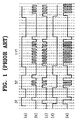
- Figure 1 shows waveform diagrams illustrating overwrite pulses for forming recording marks in a digital versatile disc random access memory (DVD-RAM).
- Figure 1 (a) shows NRZI (Non Return to Zero Inverted) data having recording marks of 3T, 5T and 11T (here, T is the period of a basic clock signal), and
- Figure 1(e) shows overwrite pulses for recording the data shown in Figure 1(a) on a disc.
- the overwrite pulses shown in Figure 1(e) are obtained by combination of a read power control signal shown in Figure 1(b), a write power control signal shown in Figure 1(c), and a bias power control signal shown in Figure 1(d).
- the overwrite pulses shown in Figure 1 are based on the 2.6 giga-byte (GB) DVD-RAM standard.
- the overwrite pulses consist of a first pulse, a multi-pulse chain and a last pulse.
- the number of pulses in the multi-pulse chain changes according to the length of a recording mark, while the first and last pulses are retained as they are.
- the rising edge of the first pulse lags the rising edge of the recording mark by T/2.
- the rising edge of the first pulse may be shifted before and after, in units of 1 nano second (ns). This is also true of the last pulse.
- the multi-pulse chain is divided into several short pulses so that the recording marks may not be deformed in the rear part of the recording marks by reducing heat accumulation.
- the overwrite pulses based on the 2.6 GB DVD-RAM standard are formed independently of correlativity between a current recording mark, a leading space and a trailing space.
- the adaptive recording method allows optimum recording to be realized by adjusting the levels of overwrite pulses or moving the positions thereof according to the correlativity between a recording mark, a leading space and a trailing space.
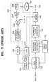
- Figure 2 is a block diagram of a conventional adaptive recording apparatus for adjusting the levels of overwrite pulses irrespective of a current recording mark, a leading space and a trailing space.
- the adaptive recording apparatus shown in Figure 2 includes a data determiner 100, a recording waveform controller 110, an overwrite pulse generator 120, a laser diode (LD) driver 140, a laser diode 160, an auto laser diode power control (ALPC) circuit 200, a driver microcomputer (MICOM) 102, a power table storing unit 104, and a multiplexer (MUX) 106.
- a data determiner 100 a recording waveform controller 110
- an overwrite pulse generator 120 a laser diode (LD) driver 140
- a laser diode 160 a laser diode 160
- an auto laser diode power control (ALPC) circuit 200 a driver microcomputer (MICOM) 102
- MICOM driver microcomputer
- MUX multiplexer
- the ALPC circuit 200 includes a photo diode (PD) 202, a variable gain controller (VGA) 204, a comparator (comp) 206, an up/down counter 208 and a digital-to-analog converter (DAC) 210, and performs an auto laser diode power control (ALPC) operation for maintaining the level of a light signal output from the LD 160, which is output as a function of PD 202 at a constant level.
- PD photo diode
- VGA variable gain controller
- DAC digital-to-analog converter
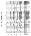
- Figure 3 shows waveform diagrams illustrating the operation of the adaptive recording apparatus shown in Figure 2.
- Figure 3(a) shows the waveform of NRZI data
- Figure 3(b) shows a read power control signal
- Figure 3(c) shows a write power control signal
- Figure 3(d) shows a bias power control signal
- Figure 3(e) shows overwrite pulses based on the 2.6 GB DVD-RAM
- Figure 3(f) shows overwrite pulses according to the adaptive recording method.
- the levels of overwrite pulses are changed into levels (1), (2) and (3) depending on the correlativity between the recording mark and leading/trailing spaces.
- the adaptive recording apparatus shown in Figure 2 operates in a normal recording mode or an adaptive recording mode.
- the levels of the overwrite pulses are controlled by light output control data supplied from the up/down counter 208 of the ALPC circuit 200.
- a reference voltage V_ref_w supplied from the driver micom 102 is applied to the comparator 206.
- the light signal reflected from the disc 180 is received in the PD 202 which is a light receiving element.
- the VGA 204 amplifies the light signal received in the PD 202.
- the comparator 206 compares the level of a voltage output from the VGA 204 and that of the reference voltage V_ref_w.
- the reference voltage V_ref_w is set according to the power of a write pulse required in a normal recording mode.
- the up/down converter 208 down-counts if the level of the light signal is higher than the reference voltage V_ref_w, and up-counts if the level of the light signal is lower than the reference voltage V_ref_w.
- the counting result of the up/down counter 208 is light output control data and is supplied to the LD driver 140 through the DAC 210.
- the MUX 106 supplies the light output control data output from the up/down counter 208 to the DAC 210.
- the levels of overwrite pulses are controlled by the light output control data stored in the power table storing unit 104.
- the power table storing unit 104 stores a power table including power setting values of overwrite pulses, wherein the power setting values depend on the correlativity between a recording mark and leading/trailing spaces.
- the power table storing unit 104 is initialized by the driver micom 102.
- the driver micom 102 reads power setting values of a control data zone, which are recorded in read-in/out zones, and stores the same in the power table storing unit 104.
- the power setting values for designating a read power level, a write power level, a bias power level, an erase power level and a cooling power level are recorded in the control data zone.
- the write power level, the bias power level, the erase power level and the cooling power level are separately recorded for each land/groove.
- 9 power setting values are recorded in the control data zone.
- the driver micom 102 controls the power setting values stored in the control data zone of the disc 180 and the power setting values that depend on the correlativity, which are stored in the flash ROM, to be stored in the power table storing unit 104.
- the power setting values depending on the correlativity may be stored in the disc 180.
- the driver micom 102 transfers the power setting values recorded in the control data zone of the disc 180 to be stored in the power table storing unit 104.
- the driver micom 102 converts the power setting values into binary data suitable for the DAC 210.
- the light output control data necessary for generating overwrite pulses which has a power level designated by the power setting values, is stored in the power table storing unit 104.
- the light output control data stored in the power table storing unit 104 may vary according to the resolution of the DAC 210 even for an identical power setting value.
- the LD driver 140 operates in accordance with the light output control data supplied from the power table storing unit 104. In other words, the LD driver 140 controls the power level of the overwrite pulse output from the LD 160 in accordance with the light output control data supplied from the power table storing unit 104.
- the MUX 106 selects the light output control data supplied from the power table storing unit 104 and supplies the same to the DAC 210.
- the data determiner 100 receives NRZI data, determines the correlativity between the recording mark and the leading/trailing spaces and then supplies the determination result to the power table storing unit 104.
- the power table storing unit 104 supplies the light output control data depending on the correlativity to the MUX 106 by referring to the determination result supplied from the data determiner 100.
- the light output control data supplied from the power table storing unit 104 is supplied to the LD driver 140 through the DAC 210, and the LD driver 140 controls the power level of the LD 160 according to the light output control data supplied from the DAC 210.
- the driver micom 102 initializes the power table storing unit 104.
- the recording waveform controller 110 outputs recording waveform control signals, that is, a read power control signal shown in Figure 3(b), a write power control signal shown in Figure 3(c) and a bias power control signal shown in Figure 3(d), according to NRZI data shown in Figure 3(a).
- the overwrite pulse generator 120 generates overwrite pulses shown in Figure 3(e), according to recording waveform control signals supplied from the recording waveform controller 110, and applies the same to the LD driver 140.
- the LD driver 140 drives the LD 160 according to the overwrite pulses applied thereto and the light output control data supplied from the DAC 210.
- the overwrite pulses supplied to the LD 160 are flashed onto the disc 180 to perform recording of data.
- the power levels of the overwrite pulses vary adaptively according to the correlativity between the recording mark and the leading/trailing spaces, as shown in Figure 3(f).
- the power level (1) represents a power level at the trailing space of a mark of 3T
- the power level (2) represents a power level at the trailing space of a mark of 5T
- the power level (3) represents a power level at the trailing space of a mark of 11T.
- the power levels of the overwrite pulses vary according to the correlativity between the recording mark and the trailing space thereof.
- the power levels may be 10 mW, 11 mW and 12 mW, respectively.
- the output characteristics of the LD 160 vary according to the length of time for which the LD 160 has been used.
- Figure 4 graphically shows the output characteristics of the LD 160, in which Figure 4(a) shows the output characteristic at 25°C, and Figure 4(b) shows the output characteristic at 60°C, respectively.
- the light output control data corresponding to the power setting values are updated according to the output characteristics of the LD 160.
- the output characteristic curves of the LD 160 are obtained using the ALPC circuit 200.
- two reference points a and b are set within the range of the output power level of the LD 160, and reference light output control data Pa and Pb for obtaining the power levels corresponding to the reference points a and b are obtained by applying voltages V_ref_a and V_ref_b corresponding the reference points a and b to the comparator 206 of the ALPC circuit 200 as reference voltages, and obtaining the counting results of the up/down counter 208 of the ALPC circuit 200.
- Approximate output characteristic curves of the LD 160 are obtained from the obtained reference light output control data Pa and Pb.
- the light output control data corresponding to the power setting values depending on the correlativity are obtained and stored in a separate power table storing unit.
- the power of the LD 160 is controlled using the light output control data stored in the power table storing unit.
- Another aim is to provide an adaptive recording apparatus which enables accurate recording, wherein the recording is adaptive to a variation in the output characteristics of a laser diode.
- an adaptive recording method for recording binary data having marks and spaces by irradiating a light signal onto an optical recording medium and adaptively adjusting the power of the light signal according to the correlativity between the length of a mark currently being recorded and the lengths of leading/trailing spaces
- the adaptive recording method comprising the steps of: (a) checking the output characteristics of a light signal generating apparatus for generating the light signal; and (b) controlling the power of the light signal by referring to the power of the light signal corresponding to the correlativity and the output characteristics in recording the data on the optical recording medium.
- the step (a) comprises the sub-steps of: (a1) obtaining first reference light output control data for outputting a light signal having a first reference power from the light signal generating apparatus; (a2) obtaining second reference light output control data for outputting a light signal having a second reference power from the light signal generating apparatus; and (a3) approximating the output characteristics of the light signal generating apparatus by referring to the first reference power, the first reference light output control data, the second reference power and the second reference light output control data.
- sub-steps (a1) and (a2) are performed in an area of the optical recording medium where user data is not recorded.
- the approximated output characteristic curve of the light signal generating apparatus is obtained by a line connecting a point corresponding to the first power and the first light output control data, and a point corresponding to the second power and the second light output control data.
- the step (b) may comprise the sub-steps of: (b1) obtaining the light output control data applied to the light signal generating apparatus for generating light signals having power levels corresponding to the power setting values depending on each correlativity; (b2) storing the light output control data; (b3) determining the correlativity between the mark currently being recorded and the leading/trailing spaces; and (b4) supplying the light output control data corresponding to the correlativity determined in the step (b3) to the light signal generating apparatus.
- the sub-steps (b1) and (b2) are periodically performed.
- the optical recording medium has two different tracks and the method further comprises the step of (b5) adding the corresponding light output control data to a difference in the light sensitivity between two tracks according to the type of a data recorded track.
- the step (a) is periodically performed.
- the optical recording medium has an area where user data is not recorded, and the step (a) is performed in that area.
- the optical recording medium is a DVD-RAM disk, and the step (a) is performed in a mirror area of the DVD-RAM disk.
- the optical recording medium may be a DVD-RAM disk, and the step (a) is performed in a gap area of the DVD-RAM disk.
- a method for controlling an adaptive recording apparatus comprising a recording waveform generator for generating an overwrite pulse control signal corresponding to binary data having marks and spaces; a laser diode driver for controlling a laser diode to generate overwrite pulses corresponding to the overwrite pulse control signal and for controlling the power of the overwrite pulses according to light output control data; an auto laser diode power control (ALPC) circuit for feed-back controlling the power of the overwrite pulses to be maintained at a predetermined reference value; a data determiner for determining the correlativity between the recording mark and leading/trailing space; a power table storing unit for storing the light output control data corresponding to the power of the overwrite pulse depending on the correlativity and outputting the corresponding light output control data according to the determined correlativity; and a multiplexer for selectively supplying the light output control data output from the power table storing unit to the laser diode driver, the adaptive recording apparatus for adaptively adjusting the
- the step (g) comprises the sub-steps of: (g1) applying to the ALPC circuit a first reference value for allowing the overwrite pulse to have a first power, and obtaining first reference light output control data corresponding thereto; (g2) applying to the ALPC circuit a second reference value for allowing the overwrite pulse to have a second power, and obtaining second reference light output control data corresponding thereto; and (g3) approximating the output characteristics of the light signal generating apparatus by referring to the first power, the first light output control data, the second power and the second light output control data.
- the sub-steps (g1) and (g2) may be performed in an area of the optical recording medium where user data is not recorded.
- the approximated output characteristic curve of the light signal generating apparatus is preferably obtained by a line connecting a point corresponding to the first power and the first light output control data, and a point corresponding to the second power and the second light output control data.
- the optical recording medium may have two different tracks and the method further comprises the step of (i) adding the corresponding light output control data to a difference in the light sensitivity between two tracks according to the type of a data recorded track.
- the step (g) is periodically performed.
- the step (g) may be performed in an area of a disk where user data is not recorded.
- the optical recording medium is a DVD-RAM disk
- the step (g) is performed in a mirror area of the DVD-RAM disk.
- the optical recording medium is a DVD-RAM disk
- the step (g) is performed in a gap area of the DVD-RAM disk.
- an adaptive recording apparatus comprising: a recording waveform generator for generating an overwrite pulse control signal corresponding to binary data having marks and spaces; a laser diode driver for controlling a laser diode to generate overwrite pulses corresponding to the overwrite pulse control signal and controlling the power of the overwrite pulses according to light output control data; an auto laser diode power control (ALPC) circuit for feed-back controlling the power of the overwrite pulses to be maintained at a predetermined reference value; a data determiner for determining the correlativity between the recording mark and leading/trailing space; a first power table storing unit for storing the light output control data corresponding to the power of the overwrite pulse depending on the correlativity; an operator for obtaining the output characteristic curve of the laser diode by referring to first reference light output control data and second reference light output control data, and outputting the corresponding light output control data according to the output characteristic curve; a second power table storing unit for storing the light output control data obtained by
- the ALPC circuit periodically outputs the first reference light output control data and the second reference light output control data, and the operator is synchronized with the period of the ALPC circuit for outputting the first reference light output control data and the second reference light output control data and outputs the light output control data corresponding to the power setting values stored in the first power table storing unit.
- the optical recording medium is a DVD-RAM disk
- the ALPC circuit is synchronized with a mirror signal indicative of a mirror period of the DVD-RAM and outputs the first reference light output control data and the second reference light output control data.
- the optical recording medium may be a DVD-RAM disk, and the ALPC circuit may be synchronized with a gap signal indicative of a gap period of the DVD-RAM and outputs the first reference light output control data and the second reference light output control data.
- the apparatus may further comprise an adder for adding the light output control data output from the second power table storing unit to the light output control data corresponding to a difference in the light sensitivity between two tracks according to the type of a land/groove track.
- FIG. 5 is a block diagram illustrating an adaptive recording apparatus according to the present invention.
- the same functional elements as those shown in Figure 2 are designated by the same reference numerals, and a detailed explanation thereof will be omitted.
- reference numeral 502 denotes a driver micom 502
- reference numeral 504 denotes a first power table storing unit
- reference numeral 508 denotes a second power table storing unit
- reference numeral 510 denotes an adder
- reference numeral 512 denotes a multiplexer (MUX).
- MUX multiplexer
- the first power table storing unit 504 stores power setting values recorded in a read in/out region of the disc 180.
- An up/down counter 208 includes three up/down counters 208a through 208c for use in calculation of first and second reference light output control data and in normal recording, respectively, which are selected by the driver micom 502 according to the operation mode.
- An operator 506 operates two reference light output control data Pa and Pb, which are obtained by the first and second up/down counters 208a and 208b, and the light output control data compensated according to a change in the output characteristic of the LD 160 using the power setting values stored in the first power table storing unit 504.
- the light output control data operated in the operator 506 is recorded in the second power table storing unit 508.
- the adder 510 adds the light output control data supplied from the second power table storing unit 508 to a predetermined value depending on the type of a track, that is, land or groove, to then supply the addition result to a MUX 512.
- the MUX 512 selects one of the light output control data supplied from the up/down counters 208a through 208c and the adder 510 and supplies the selected data to a DAC 210.
- the MUX 512 selects the first or second up/down counter 208a or 208b in a compensation mode, selects the third up/down counter 208c in a general recording mode, and selects the adder 510 in an adaptive recording mode.
- the apparatus shown in Figure 5 operates in any one of a power table compensation mode for obtaining light output control data compensated according to a variation in the output characteristic of the LD 160, a general recording mode and an adaptive recording mode.
- the power table compensation mode is preferably periodically executed.
- the power table compensation mode is periodically executed. In other words, the output characteristic of the LD 160 is periodically examined and the light output control data of the second power table storing unit 508 is compensated according to the examination result.
- the first reference light output control data Pa and the second reference light output control data Pb are obtained to be supplied to the operator 506, the output characteristic of the LD 160 is examined by referring to the obtained reference light output control data, and the second power table storing unit 508 is updated.
- the power table compensation mode is executed in an area of the disc 180, where user data is not recorded, for example, a mirror/gap section of a DVD-RAM disc.
- the power table compensation mode is executed in synchronization with a mirror/gap signal indicative of the mirror/gap section, and is preferably executed within the mirror/gap section.
- a mirror section is a region in which data is not recorded and a gap section is a recording region of data except user data, the compensation mode can be executed without affecting the recording operation.
- the output characteristics of the LD 160 are examined and the second power table storing unit 508 is compensated according to the examination result.
- Figure 6 is a conceptual diagram showing a procedure of inspecting the output characteristics of the laser diode 160 shown in Figure 5.
- approximation is used for examining the output characteristics of the LD 160.
- two reference light output control data Pa and Pb are obtained at two references a and b selected on the y axis indicating the power of the overwrite pulse.
- An approximate curve of the output characteristics of the LD 160 is obtained from two references a and b and the corresponding reference light output control data Pa and Pb.
- a straight line connecting the points [Pa, a] and [Pb, b] is obtained and assumed to be an approximate output characteristic curve.
- the driver micom 502 examines the first reference light output control data Pa at the first reference a and then examines the second reference light output control data Pb at the second reference b , thereby obtaining the output characteristic curve of the LD 160 by referring to the first reference light output control data Pa and the second reference light output control data Pb obtained at the first reference a and the second reference b , respectively.
- the dynamic power of the LD 160 ranges from 2 to 15 mW
- the power level of the first reference a is 6 mW
- the second reference b is 10 mW.
- the reference light output control data Pa and Pb to be applied to the LD 160 are obtained.
- the ALPC circuit 200 is involved in examining the reference light output control data Pa and Pb at the first and second references a and b .
- the first reference light output control data Pa of the first reference a (6 mW) is obtained as follows.
- the driver micom 502 makes the first up/down counter 208a operate and makes the MUX 512 select the output of the first up/down counter 208a. Then, the driver micom 502 applies to the comparator 206 a reference voltage V_ref_6mW for determining the first reference a of 6 mW.
- the first reference light output control data Pa for obtaining the power level of the overwrite pulse corresponding to first reference of 6 mW is obtained in the first up/down counter 208a to then be supplied to the operator 506. This operation is performed in the mirror/gap section.
- the second reference light output control data Pb of the first reference b (10 mW) is obtained as follows.
- the driver micom 502 makes the second up/down counter 208b operate and makes the MUX 512 select the output of the second up/down counter 208b. Then, the driver micom 502 applies to the comparator 206 a reference voltage V_ref_10mW for determining the first reference b of 10 mW.
- the second reference light output control data Pb for obtaining the power level of the overwrite pulse corresponding to second reference of 10 mW is obtained in the second up/down counter 208b to then be supplied to the operator 506. This operation is also performed in the mirror/gap section.
- the operator 506 obtains the approximate output characteristic curve by the known method shown in Figure 6 by referring to the first reference light output control data Pa and the second reference light output control data Pb obtained at the first reference a and the second reference b .
- the coordinates [Pa, a] defined by the first reference a and the first reference light output control data Pa, and the coordinates [Pb, b] defined by the second reference b and the second reference light output control data Pb are linearly connected to each other to obtain the approximate output characteristic curve.
- the light output control data of the second power table storing unit 508 is updated based on the obtained approximate output characteristic curve.
- the power level of the overwrite pulse is compensated in accordance with all possible combinations of the length of a recoding mark and the length of leading/trailing space.
- compensation is preferably made on the first pulse, the last pulse and the multi and the multi-pulse chain, respectively.
- the power levels of the first pulse and the last pulse for example, are compensated.
- the compensation degrees of the first and last pulses may be different from each other.
- it has been illustrated that the power levels of the first and last pulses are equally compensated.
- the length of the shortest pulse of a NRZI signal is 3T (Here, T is a period of a system clock signal.) and that of the longest pulse of the NRZI signal is 14T. Therefore, there are 12 2 possible combinations of the length of a recoding mark and the length of leading/trailing space.
- the size of a power table for covering all possible combinations increases and the system load increases. Accordingly, the length of a recording mark and the length of trailing space are classified into several representative types, for example, four types of the shortest pulse, the short pulse, the middle pulse and the long pulse, for easier processing. Then, a power table for compensated power levels of 16 (4 ⁇ 4)kinds of combinations can be used.
- Figure 7 (a) shows the content of the power table in which the compensated power levels of the representative combinations, in which the power level of the last pulse is adjusted according to the length of a recording mark and the length of trailing space.
- G1, G2, G3 and G4 represent the shortest pulse (3T), the short pulse (4T), the middle pulse (5T) and the long pulse (6T to 14T), respectively.
- Figure 7 (b) shows the light output control data compensated responsive to a variation in the output characteristic of the LD 160.
- the operator 506 prepares the approximate output characteristic curve using the reference light output control data and updates the light output control data corresponding to the power setting values by referring to the prepared approximate output characteristic curve.
- the updated light output control data are stored in the second power table storing unit 508.
- the updating operation is repeatedly performed.
- the second power table storing unit 508 is referred to when the data is recorded by the adaptive recording mode.
- FIGs 7(a) and 7(b) illustrate an example of an adaptive recording method depending on the correlativity between the recording mark and the trailing space
- the adaptive recording method may depend on the correlativity between the recording mark and the leading space or the leading/trailing spaces.
- Figure 8 graphically illustrates a procedure of updating light output control data, in which the curve A is an approximate output characteristic curve obtained at 25°C and the curve b is an approximate output characteristic curve obtained at 60°C.
- the contents recorded in the first power table storing unit 504 are data indicating the power level of an overwrite pulse to be set in the corresponding correlativity.
- the power level of the last pulse is to be set to 10 mW.
- the light output control data for 10 mW of the power level of the LD 160 is 100.
- the light output control data for the same power level is 120.
- the output characteristic is dependent on the temperature and the temperature is subject to change at any time
- the output characteristic of the LD 160 changes at any time.
- the light output control data must be changed according to changes in the output characteristic of the LD 160.
- the operator 506 performs an operation on the light output control data compensated with respect to the correlativity by referring to the approximate output characteristic curves and stores the operation result in the second power table storing unit 508.
- the second power table storing unit 508 is referred to.
- the first power table storing unit 504 and the second power table storing unit 508 are separately provided for storing initial data for an adaptive recording method and ensuring responsiveness.
- the light power level is controlled by the ALPC circuit 200.
- a reference voltage V_ref_w supplied by the driver micom 502 is applied to the comparator 206 and the third up/down counter 208c is used.
- the recording waveform controller 110 outputs recording waveform control signals, that is, the read power control signal shown in Figure 3(b), the write power control signal shown in Figure 3(c) and the bias power control signal shown in Figure 3(d), according to NRZI data shown in Figure 4(a).
- the overwrite pulse generator 120 generates overwrite pulses shown in Figure 3(e), according to recording waveform control signals supplied from the recording waveform controller 110, and applies the same to the LD driver 140.
- the LD driver 140 drives the LD 160 according to the overwrite pulses applied thereto and the light output control data supplied from the DAC 210.
- the overwrite pulses supplied to the LD 160 are flashed onto the disc 180 to perform recording of data. Data is recorded on the disk 180 by the overwrite pulses generated in the LD 160.
- the output levels of the LD 160 are adjusted by referring to the compensated light output control data stored in the second power table storing unit 508.
- setting the power levels of overwrite pulses is achieved by the data determiner 100, the second power table storing unit 508, the adder 510, the MUX 512, the DAC 210 and the LD driver 140.
- the data determiner 100 receives NRZI data, determines the correlativity between the length of the recording mark and the length of leading/trailing space, and supplies the determination result to the second power table storing unit 508.
- the second power table storing unit 508 outputs the light output control data of the corresponding correlativity to the adder 510 by referring to the determination result supplied from the data determiner 100.
- the adder 510 adds the light output control data output from the second power table storing unit 508 to the light output control data depending to the land/groove.
- the power table storing unit for use in land and groove must be separately installed.
- the difference in the light sensitivity between a land track and a groove track is about 0.5 mW, which is substantially constant throughout the disk.
- the light output control data corresponding to 0.5 mW is added for each land/groove track, thereby obviating the hardware burden due to the demand for separately installing the second power table storing unit 508 for land/groove use.
- the adder 510 outputs only the light output control data supplied from the second power table storing unit 508 or outputs light output control data obtained by adding a constant value (light output control data corresponding to about 0.5 mW) to the same according to a land/groove signal.
- the land/groove signal is generated in a tracking controller (not shown).
- the addition result of the adder 510 is supplied to the LD driver 140 via the MUX 512 and the DAC 210.
- the LD driver 140 controls the levels of the overwrite pulses output from the LD 160 according to the light output control data supplied from the DAC 210.
- the driver micom 502 initializes the determination conditions of the data determiner 100, the first power table storing unit 504 and the second power table storing unit 508.
- the power setting values read from the lead-in/out zone of the disk 180 are stored in the first power table storing unit 504, and the light output control data corresponding to the power setting values stored in the first power table storing unit 504 is stored in the second power table storing unit 508.
- the second power table storing unit 508 stores the light output control data updated according to the output characteristics of the LD 160.
- the recording waveform controller 110 outputs recording waveform control signals, that is, the read power control signal shown in Figure 3 (b), the write power control signal shown in Figure 3(c) and the bias power control signal shown in Figure 3(d), according to NRZI data shown in Figure 4(a).
- the overwrite pulse generator 120 generates overwrite pulses shown in Figure 3(e), according to recording waveform control signals supplied from the recording waveform controller 110, and applies the same to the LD driver 140.
- the LD driver 140 drives the LD 160 according to the overwrite pulses applied thereto and the light output control data supplied from the DAC 210.
- the ALPC circuit 200 performs an ALPC operation, like in the general recording mode. Since the counted values of the third up/down counter 208c are changed by adjusting the light output levels in the adaptive recording mode, the normal recording mode may be affected. However, in the general adaptive recording mode, level adjustment is performed with respect to the first and last pulses of the overwrite pulses. The periods of the first and last pulses are shorter than those that can be managed by the ALPC circuit 200. Thus, the third up/down counter 208c is little affected by the level adjustment of the first and last pulses. If affected, since the effect of the level adjustment is distributed throughout several adjacent recording marks, the effect is negligible.
- the operation of the ALPC circuit 200 may be disabled.
- Table 1 shows the types of adaptive recording modes.
- Figure 9 shows waveform diagrams of overwrite pulses according to the adaptive recording mode based on Table 1.
- the levels of the overwrite pulses adaptively vary, as shown in Figure 9.
- Figure 9(a) shows overwrite pulses in the case of varying the level of the first pulse according to the correlativity between the recording mark and the leading space, that is, in the case of AP_TYPE[0, 0]
- Figure 9(b) shows overwrite pulses in the case of varying the level of the last pulse according to the correlativity between the recording mark and the trailing space, that is, in the case of AP_TYPE[0, 1]
- Figure 9(c) shows overwrite pulses in the case of varying the levels of the first and last pulses according to the correlativity between the recording mark and the leading/trailing spaces, that is, in the case of AP_TYPE[1, 0]
- Figure 9(d) shows overwrite pulses in the case of varying the levels of all pulses according to the corre
- the adaptive recording method according to the present invention allows accurate recording control by updating the light output control data for the power setting values as the output characteristics of a laser diode change.
- the power of overwrite pulses can vary adaptively according to the lengths of recording marks and spaces.
Landscapes
- Physics & Mathematics (AREA)
- Optics & Photonics (AREA)
- Optical Recording Or Reproduction (AREA)
- Optical Head (AREA)
Abstract
Description
| b1 | b2 | Type of adaptive recording mode | |
| AP_TYPE[b1, b2] | 0 | 0 | |
| 0 | 1 | | |
| 1 | 0 | First pulse, | |
| 1 | 1 | First pulse, multi-pulse, last pulse |
Claims (25)
- An adaptive recording method for recording binary data having marks and spaces by irradiating a light signal onto an optical recording medium and adaptively adjusting the power of the light signal according to the correlativity between the length of a mark currently being recorded and the lengths of leading/trailing spaces, the adaptive recording method comprising the steps of:(a) checking the output characteristics of a light signal generating apparatus for generating the light signal; and(b) controlling the power of the light signal by referring to the power of the light signal corresponding to the correlativity and the output characteristics in recording the data on the optical recording medium.
- The adaptive recording method according to claim 1, wherein the step (a) comprises the sub-steps of:(a1) obtaining first reference light output control data for outputting a light signal having a first reference power from the light signal generating apparatus;(a2) obtaining second reference light output control data for outputting a light signal having a second reference power from the light signal generating apparatus; and(a3) approximating the output characteristics of the light signal generating apparatus by referring to the first reference power, the first reference light output control data, the second reference power and the second reference light output control data.
- The adaptive recording method according to claim 2, wherein the sub-steps (a1) and (a2) are performed in an area of the optical recording medium where user data is not recorded.
- The adaptive recording method according to claim 2 or 3, wherein in the sub-step (a3), the approximated output characteristic curve of the light signal generating apparatus is obtained by a line connecting a point corresponding to the first power and the first light output control data, and a point corresponding to the second power and the second light output control data.
- The adaptive recording method according to any of claims 1 to 4, wherein the step (b) comprises the sub-steps of:(b1) obtaining the light output control data applied to the light signal generating apparatus for generating light signals having power levels corresponding to the power setting values depending on each correlativity;(b2) storing the light output control data;(b3) determining the correlativity between the mark currently being recorded and the leading/trailing spaces; and(b4) supplying the light output control data corresponding to the correlativity determined in the step (b3) to the light signal generating apparatus.
- The adaptive recording method according to claim 5, wherein the sub-steps (b1) and (b2) are periodically performed.
- The adaptive recording method according to claim 5 or 6, wherein the optical recording medium has two different tracks and the method further comprises the step of (b5) adding the corresponding light output control data to a difference in the light sensitivity between two tracks according to the type of a data recorded track.
- The adaptive recording method according any preceding claim, wherein the step (a) is periodically performed.
- The adaptive recording method according to any preceding claim, wherein the optical recording medium has an area where user data is not recorded, and the step (a) is performed in that area.
- The adaptive recording method according to any preceding claim, wherein the optical recording medium is a DVD-RAM disk, and the step (a) is performed in a mirror area of the DVD-RAM disk.
- The adaptive recording method according to any of claims 1 to 9, wherein the optical recording medium is a DVD-RAM disk, and the step (a) is performed in a gap area of the DVD-RAM disk.
- A method for controlling an adaptive recording apparatus comprising a recording waveform generator (120) for generating an overwrite pulse control signal corresponding to binary data having marks and spaces; a laser diode driver (140) for controlling a laser diode (160) to generate overwrite pulses corresponding to the overwrite pulse control signal and for controlling the power of the overwrite pulses according to light output control data; an auto laser diode power control (ALPC) circuit (200) for feed-back controlling the power of the overwrite pulses to be maintained at a predetermined reference value; a data determiner (100) for determining the correlativity between the recording mark and leading/trailing space; a power table storing unit (508) for storing the light output control data corresponding to the power of the overwrite pulse depending on the correlativity and outputting the corresponding light output control data according to the determined correlativity; and a multiplexer (512) for selectively supplying the light output control data output from the power table storing unit (508) to the laser diode driver (140), the adaptive recording apparatus for adaptively adjusting the power of the overwrite pulse according to the correlativity between the length of the recording mark and the lengths of the leading/trailing spaces, the method comprising the steps:(g) checking the output characteristic curve of the laser diode (160) by controlling the ALPC circuit (200); and(h) updating the light output control data stored in the power table storing unit (508) by referring to the output characteristic curve.
- The adaptive recording apparatus controlling method according to claim 12, wherein the step (g) comprises the sub-steps of:(g1) applying to the ALPC circuit (200) a first reference value for allowing the overwrite pulse to have a first power, and obtaining first reference light output control data corresponding thereto;(g2) applying to the ALPC circuit (200) a second reference value for allowing the overwrite pulse to have a second power, and obtaining second reference light output control data corresponding thereto; and(g3) approximating the output characteristics of the light signal generating apparatus by referring to the first power, the first light output control data, the second power and the second light output control data.
- The adaptive recording apparatus controlling method according to claim 13, wherein the sub-steps (g1) and (g2) are performed in an area of the optical recording medium (180) where user data is not recorded.
- The adaptive recording apparatus controlling method according to claim 13, wherein in the sub-step (g3), the approximated output characteristic curve of the light signal generating apparatus is obtained by a line connecting a point corresponding to the first power and the first light output control data, and a point corresponding to the second power and the second light output control data.
- The adaptive recording apparatus controlling method according to claim 12, wherein the optical recording medium (180) has two different tracks and the method further comprises the step of (i) adding the corresponding light output control data to a difference in the light sensitivity between two tracks according to the type of a data recorded track.
- The adaptive recording apparatus controlling method according to claim 12, wherein the step (g) is periodically performed.
- The adaptive recording apparatus controlling method according to claim 12, wherein the step (g) is performed in an area of a disk where user data is not recorded.
- The adaptive recording apparatus controlling method according to claim 12, wherein the optical recording medium is a DVD-RAM disk, and the step (g) is performed in a mirror area of the DVD-RAM disk.
- The adaptive recording apparatus controlling method according to claim 12, wherein the optical recording medium is a DVD-RAM disk, and the step (g) is performed in a gap area of the DVD-RAM disk.
- An adaptive recording apparatus comprising:a recording waveform generator (120) for generating an overwrite pulse control signal corresponding to binary data having marks and spaces;a laser diode driver (140) for controlling a laser diode (140) to generate overwrite pulses corresponding to the overwrite pulse control signal and controlling the power of the overwrite pulses according to light output control data;an auto laser diode power control (ALPC) circuit (200) for feed-back controlling the power of the overwrite pulses to be maintained at a predetermined reference value;a data determiner (100) for determining the correlativity between the recording mark and leading/trailing space;a first power table storing unit (504) for storing the light output control data corresponding to the power of the overwrite pulse depending on the correlativity;an operator (506) for obtaining the output characteristic curve of the laser diode (160) by referring to first reference light output control data and second reference light output control data, and outputting the corresponding light output control data according to the output characteristic curve;a second power table storing unit (508) for storing the light output control data obtained by the operator (506); anda multiplexer (512) for selectively supplying the light output control data output from the ALPC circuit (200) or the second power table storing unit (508) to the laser diode driver (140), the adaptive recording apparatus for adaptively adjusting the power of the overwrite pulse according to the correlativity between the length of the recording mark and the lengths of the leading/trailing spaces.
- The adaptive recording apparatus according to claim 21, wherein the ALPC circuit (200) periodically outputs the first reference light output control data and the second reference light output control data, and the operator (506) is synchronized with the period of the ALPC circuit (200) for outputting the first reference light output control data and the second reference light output control data and outputs the light output control data corresponding to the power setting values stored in the first power table storing unit (504).
- The adaptive recording apparatus according to claim 22, wherein the optical recording medium is a DVD-RAM disk, and the ALPC circuit is synchronized with a mirror signal indicative of a mirror period of the DVD-RAM and outputs the first reference light output control data and the second reference light output control data.
- The adaptive recording apparatus according to claim 22, wherein the optical recording medium is a DVD-RAM disk, and the ALPC circuit (200) is synchronized with a gap signal indicative of a gap period of the DVD-RAM and outputs the first reference light output control data and the second reference light output control data.
- The adaptive recording apparatus according to claim 23 or 24, further comprising an adder (510) for adding the light output control data output from the second power table storing unit to the light output control data corresponding to a difference in the light sensitivity between two tracks according to the type of a land/groove track.
Applications Claiming Priority (2)
| Application Number | Priority Date | Filing Date | Title |
|---|---|---|---|
| KR1019990022916A KR100322601B1 (en) | 1999-06-18 | 1999-06-18 | Recording method for optical disk recording, control method for optical disk recording apparatus, and recording apparatus of optical disk |
| KR9922916 | 1999-06-18 |
Publications (3)
| Publication Number | Publication Date |
|---|---|
| EP1061509A2 true EP1061509A2 (en) | 2000-12-20 |
| EP1061509A3 EP1061509A3 (en) | 2003-01-15 |
| EP1061509B1 EP1061509B1 (en) | 2004-11-10 |
Family
ID=19593334
Family Applications (1)
| Application Number | Title | Priority Date | Filing Date |
|---|---|---|---|
| EP00304975A Expired - Lifetime EP1061509B1 (en) | 1999-06-18 | 2000-06-13 | Adaptive recording method and apparatus for high-density optical recording, and control method therefor |
Country Status (7)
| Country | Link |
|---|---|
| US (1) | US6661759B1 (en) |
| EP (1) | EP1061509B1 (en) |
| JP (1) | JP2001023175A (en) |
| KR (1) | KR100322601B1 (en) |
| CN (1) | CN1150524C (en) |
| DE (1) | DE60015653T2 (en) |
| MY (1) | MY125184A (en) |
Cited By (3)
| Publication number | Priority date | Publication date | Assignee | Title |
|---|---|---|---|---|
| EP1383118A3 (en) * | 2002-07-15 | 2005-01-19 | Pioneer Corporation | Apparatus and method for information recording, and device and method for waveform data generation |
| EP1349244A3 (en) * | 2002-03-29 | 2005-07-06 | Samsung Electronics Co., Ltd. | Laser diode driver, optical pickup device, and optical recording/reproducing apparatus using the same |
| EP1471513A3 (en) * | 2003-04-21 | 2006-10-18 | Pioneer Corporation | Information recording apparatus and information recording method |
Families Citing this family (17)
| Publication number | Priority date | Publication date | Assignee | Title |
|---|---|---|---|---|
| JP3730084B2 (en) * | 2000-05-19 | 2005-12-21 | パイオニア株式会社 | Light control circuit |
| JP4051904B2 (en) * | 2001-07-31 | 2008-02-27 | ヤマハ株式会社 | Recording signal waveform correction method in optical disc recording, recording signal waveform correction data storage method, and optical disc recording apparatus |
| JP2003123252A (en) * | 2001-10-09 | 2003-04-25 | Hitachi Ltd | Information recording method and information recording device |
| EP1341164A3 (en) * | 2002-02-21 | 2004-12-01 | Mitsumi Electric Co., Ltd. | Optical power level-controlling device for stable oscillation of laser diode |
| CN100334619C (en) | 2002-04-19 | 2007-08-29 | 松下电器产业株式会社 | Optical information recording method, optical information recording device, and optical information recording medium |
| TWI234776B (en) * | 2002-09-12 | 2005-06-21 | Via Tech Inc | Power control method of a pick-up head of an optical disk drive |
| US20040130993A1 (en) * | 2003-01-02 | 2004-07-08 | Nedi Nadershahi | Method and apparatus for a high speed write strategy |
| EP1482486A3 (en) | 2003-05-27 | 2007-06-27 | Matsushita Electric Industrial Co., Ltd. | Optical information recording method, optical information recording device and optical information recording medium |
| KR100889715B1 (en) * | 2003-07-18 | 2009-03-23 | 미츠비시 가가쿠 메디아 가부시키가이샤 | Optical recording method |
| US20060000814A1 (en) * | 2004-06-30 | 2006-01-05 | Bo Gu | Laser-based method and system for processing targeted surface material and article produced thereby |
| CN100538835C (en) * | 2004-07-16 | 2009-09-09 | 皇家飞利浦电子股份有限公司 | Method of optimizing write power for recording marks onto an information layer of a record carrier and recording device using such optimization method |
| CN100356454C (en) * | 2004-09-21 | 2007-12-19 | 联发科技股份有限公司 | Laser power control circuit and method thereof |
| KR100653493B1 (en) | 2005-05-26 | 2006-12-05 | 주식회사 히타치엘지 데이터 스토리지 코리아 | Laser power setting method of optical disk device |
| CN101331546B (en) * | 2005-12-12 | 2011-03-30 | 松下电器产业株式会社 | Laser energy control method and optical information recording and reproducing device |
| CN101197140B (en) * | 2006-12-05 | 2011-07-27 | 鸿富锦精密工业(深圳)有限公司 | Burning power regulation method and device of CD drive |
| JP4697298B2 (en) * | 2008-12-19 | 2011-06-08 | ソニー株式会社 | Comparator and optical disk recording / reproducing apparatus |
| CN110715790A (en) * | 2018-07-13 | 2020-01-21 | 中兴通讯股份有限公司 | Pulse testing method and device, testing equipment and storage medium |
Family Cites Families (27)
| Publication number | Priority date | Publication date | Assignee | Title |
|---|---|---|---|---|
| JPH01232545A (en) * | 1987-11-19 | 1989-09-18 | Olympus Optical Co Ltd | Optical recording method and optical disk device |
| JPH03171437A (en) | 1989-11-30 | 1991-07-24 | Matsushita Electric Ind Co Ltd | Signal recording method and optimum power setting device |
| JP2797733B2 (en) | 1990-03-14 | 1998-09-17 | 松下電器産業株式会社 | Recording method for optical information recording member |
| US5185734A (en) * | 1990-07-20 | 1993-02-09 | International Business Machines Corporation | Calibrating and power-protecting laser drive circuits |
| US5216659A (en) | 1991-09-11 | 1993-06-01 | International Business Machines | Laser power calibration by measuring laser drive current at out of focus and in focus conditions |
| US5268893A (en) | 1991-10-18 | 1993-12-07 | International Business Machines Corporation | Write power calibration utilizing least squares fit of read-back signals for moving media memory |
| EP0559391B1 (en) | 1992-03-03 | 1998-06-03 | Canon Kabushiki Kaisha | Magnetooptical recording/reproducing method and apparatus |
| US5341360A (en) | 1992-06-05 | 1994-08-23 | Maxoptix Corporation | Method and apparatus for calibrating laser write power by averaging upper and lower knees of a calibration profile |
| US5490126A (en) * | 1993-04-07 | 1996-02-06 | Matsushita Electric Industrial Co., Ltd. | Apparatus for recording and reproducing data on a disk |
| JPH07105563A (en) * | 1993-10-05 | 1995-04-21 | Nikon Corp | Optical disc and optical disc device |
| JP3177116B2 (en) | 1994-04-20 | 2001-06-18 | 松下電器産業株式会社 | Optical information recording medium and optical recording / reproducing device |
| JP2734988B2 (en) * | 1994-05-19 | 1998-04-02 | 日本ビクター株式会社 | Optical disk drive |
| US5602814A (en) * | 1994-10-06 | 1997-02-11 | International Business Machines Corporation | Calibration of write-once disks using a single disk sector |
| JPH09115165A (en) * | 1995-10-20 | 1997-05-02 | Olympus Optical Co Ltd | Semiconductor laser circuit |
| JPH09171632A (en) * | 1995-12-20 | 1997-06-30 | Ricoh Co Ltd | Recording power correction device for optical disc recording device and optical disc |
| JPH09212866A (en) * | 1996-02-08 | 1997-08-15 | Taiyo Yuden Co Ltd | Power calibration method for write-once optical disk and optical disk recording and reproducing device |
| US5640381A (en) * | 1996-03-08 | 1997-06-17 | International Business Machines Corporation | Laser power-drive circuit having a scaling DAC supplying a scaled reference signal to a plurality of scaled DAC's that supply a plurality of scaled output signals |
| JP3457463B2 (en) * | 1996-04-26 | 2003-10-20 | 富士通株式会社 | Optical storage |
| JPH09180195A (en) | 1996-12-16 | 1997-07-11 | Fujitsu Ltd | Optical disk information writing control method and apparatus therefor |
| JP3608926B2 (en) * | 1996-12-26 | 2005-01-12 | 株式会社日立製作所 | Information recording device |
| US5802031A (en) * | 1997-01-28 | 1998-09-01 | International Business Machines Corporation | Programmable PPM/PWM writing system for optical disk |
| JP3648914B2 (en) * | 1997-04-11 | 2005-05-18 | ソニー株式会社 | Laser light power control method and optical disk recording apparatus |
| KR19990016023A (en) | 1997-08-12 | 1999-03-05 | 윤종용 | Laser diode light output control method and device |
| JP3323782B2 (en) | 1997-09-09 | 2002-09-09 | 株式会社日立製作所 | How information is recorded |
| JPH11213429A (en) * | 1998-01-30 | 1999-08-06 | Sony Corp | Recording device and recording method for phase change optical disk |
| JP4075185B2 (en) * | 1999-01-29 | 2008-04-16 | 松下電器産業株式会社 | Optical information recording / reproducing method and optical information recording / reproducing apparatus |
| WO2002023576A1 (en) | 2000-09-18 | 2002-03-21 | Mapper Lithography Ip B.V. | Field emission photocathode array comprising an additional layer to improve the yield and electron optical imaging system using the same |
-
1999
- 1999-06-18 KR KR1019990022916A patent/KR100322601B1/en not_active Expired - Fee Related
-
2000
- 2000-06-13 DE DE60015653T patent/DE60015653T2/en not_active Expired - Lifetime
- 2000-06-13 EP EP00304975A patent/EP1061509B1/en not_active Expired - Lifetime
- 2000-06-16 JP JP2000181812A patent/JP2001023175A/en active Pending
- 2000-06-16 MY MYPI20002733 patent/MY125184A/en unknown
- 2000-06-18 CN CNB001226703A patent/CN1150524C/en not_active Expired - Fee Related
- 2000-06-19 US US09/597,994 patent/US6661759B1/en not_active Expired - Lifetime
Cited By (5)
| Publication number | Priority date | Publication date | Assignee | Title |
|---|---|---|---|---|
| EP1349244A3 (en) * | 2002-03-29 | 2005-07-06 | Samsung Electronics Co., Ltd. | Laser diode driver, optical pickup device, and optical recording/reproducing apparatus using the same |
| US7298766B2 (en) | 2002-03-29 | 2007-11-20 | Samsung Electronics Co., Ltd. | Laser diode driver and driving method for controlling auto laser power, optical pickup device, and optical recording/reproducing apparatus using the same |
| EP1383118A3 (en) * | 2002-07-15 | 2005-01-19 | Pioneer Corporation | Apparatus and method for information recording, and device and method for waveform data generation |
| CN1305042C (en) * | 2002-07-15 | 2007-03-14 | 日本先锋公司 | Information recorder and method, waveform data reproducer and method |
| EP1471513A3 (en) * | 2003-04-21 | 2006-10-18 | Pioneer Corporation | Information recording apparatus and information recording method |
Also Published As
| Publication number | Publication date |
|---|---|
| EP1061509A3 (en) | 2003-01-15 |
| EP1061509B1 (en) | 2004-11-10 |
| CN1150524C (en) | 2004-05-19 |
| JP2001023175A (en) | 2001-01-26 |
| MY125184A (en) | 2006-07-31 |
| US6661759B1 (en) | 2003-12-09 |
| KR20010002872A (en) | 2001-01-15 |
| KR100322601B1 (en) | 2002-03-18 |
| DE60015653D1 (en) | 2004-12-16 |
| DE60015653T2 (en) | 2005-10-20 |
| CN1278639A (en) | 2001-01-03 |
Similar Documents
| Publication | Publication Date | Title |
|---|---|---|
| EP1061509B1 (en) | Adaptive recording method and apparatus for high-density optical recording, and control method therefor | |
| JP3457463B2 (en) | Optical storage | |
| US7139227B2 (en) | Device and method for recording data to optical disk using recording pulse with corrected edge position | |
| US7200091B2 (en) | Light source driving unit and optical storage apparatus | |
| US7142486B2 (en) | Signal processing method and signal processing apparatus | |
| EP1058246B1 (en) | Method and apparatus of controlling power supplied to laser diode | |
| EP1601069A2 (en) | Laser diode driver, optical pickup device, and optical recording/reproducing apparatus using the same | |
| US8115661B2 (en) | Automatic power control system for optical disc drive and method thereof | |
| US7298680B2 (en) | Optical disc apparatus | |
| US20030169659A1 (en) | Information recording method, recording condition detection method, and information recording apparatus | |
| US7420906B2 (en) | Automatic power calibration apparatus for optical recording device and automatic power calibration method therefor | |
| US6243342B1 (en) | Method and apparatus for controlling optical output of laser diode | |
| KR20070008722A (en) | Optical power control | |
| KR20040049807A (en) | Recording apparatus and its laser power control method | |
| JP3961883B2 (en) | Information recording device | |
| JP2005347477A (en) | Semiconductor laser drive device | |
| JP2003132571A (en) | Light source drive | |
| JP3839301B2 (en) | Optical information recording device | |
| US7583571B2 (en) | Write based power adaptive control system | |
| JP4145519B2 (en) | Light source drive device | |
| JP3839300B2 (en) | Optical information recording device | |
| JP4187958B2 (en) | Light source driving apparatus and optical information recording / reproducing apparatus including the light source driving apparatus | |
| JP3875534B2 (en) | Optical information recording device | |
| KR20050057077A (en) | Apparatus for sensing defect of optical disk | |
| JP2002352462A (en) | Optical storage |
Legal Events
| Date | Code | Title | Description |
|---|---|---|---|
| PUAI | Public reference made under article 153(3) epc to a published international application that has entered the european phase |
Free format text: ORIGINAL CODE: 0009012 |
|
| 17P | Request for examination filed |
Effective date: 20000623 |
|
| AK | Designated contracting states |
Kind code of ref document: A2 Designated state(s): AT BE CH CY DE DK ES FI FR GB GR IE IT LI LU MC NL PT SE |
|
| AX | Request for extension of the european patent |
Free format text: AL;LT;LV;MK;RO;SI |
|
| PUAL | Search report despatched |
Free format text: ORIGINAL CODE: 0009013 |
|
| AK | Designated contracting states |
Kind code of ref document: A3 Designated state(s): AT BE CH CY DE DK ES FI FR GB GR IE IT LI LU MC NL PT SE |
|
| AX | Request for extension of the european patent |
Free format text: AL;LT;LV;MK;RO;SI |
|
| RIC1 | Information provided on ipc code assigned before grant |
Free format text: 7G 11B 7/125 A, 7H 01S 5/0683 B, 7G 11B 7/00 B |
|
| 17Q | First examination report despatched |
Effective date: 20030318 |
|
| AKX | Designation fees paid |
Designated state(s): DE FR GB NL |
|
| GRAP | Despatch of communication of intention to grant a patent |
Free format text: ORIGINAL CODE: EPIDOSNIGR1 |
|
| GRAS | Grant fee paid |
Free format text: ORIGINAL CODE: EPIDOSNIGR3 |
|
| GRAA | (expected) grant |
Free format text: ORIGINAL CODE: 0009210 |
|
| AK | Designated contracting states |
Kind code of ref document: B1 Designated state(s): DE FR GB NL |
|
| REG | Reference to a national code |
Ref country code: GB Ref legal event code: FG4D |
|
| REG | Reference to a national code |
Ref country code: IE Ref legal event code: FG4D |
|
| REF | Corresponds to: |
Ref document number: 60015653 Country of ref document: DE Date of ref document: 20041216 Kind code of ref document: P |
|
| PLBE | No opposition filed within time limit |
Free format text: ORIGINAL CODE: 0009261 |
|
| STAA | Information on the status of an ep patent application or granted ep patent |
Free format text: STATUS: NO OPPOSITION FILED WITHIN TIME LIMIT |
|
| ET | Fr: translation filed | ||
| 26N | No opposition filed |
Effective date: 20050811 |
|
| REG | Reference to a national code |
Ref country code: GB Ref legal event code: 732E Free format text: REGISTERED BETWEEN 20140904 AND 20140910 |
|
| REG | Reference to a national code |
Ref country code: DE Ref legal event code: R082 Ref document number: 60015653 Country of ref document: DE Representative=s name: GRUENECKER, KINKELDEY, STOCKMAIR & SCHWANHAEUS, DE |
|
| REG | Reference to a national code |
Ref country code: FR Ref legal event code: TP Owner name: TOSHIBA SAMSUNG STORAGE TECHNOLOGY KOREA CORPO, KR Effective date: 20141003 |
|
| REG | Reference to a national code |
Ref country code: DE Ref legal event code: R082 Ref document number: 60015653 Country of ref document: DE Representative=s name: GRUENECKER, KINKELDEY, STOCKMAIR & SCHWANHAEUS, DE Effective date: 20141016 Ref country code: DE Ref legal event code: R081 Ref document number: 60015653 Country of ref document: DE Owner name: TOSHIBA SAMSUNG STORAGE TECHNOLOGY KOREA CORP., KR Free format text: FORMER OWNER: SAMSUNG ELECTRONICS CO., LTD., SUWON, KYONGGI, KR Effective date: 20141016 Ref country code: DE Ref legal event code: R082 Ref document number: 60015653 Country of ref document: DE Representative=s name: GRUENECKER PATENT- UND RECHTSANWAELTE PARTG MB, DE Effective date: 20141016 |
|
| REG | Reference to a national code |
Ref country code: NL Ref legal event code: SD Effective date: 20150304 |
|
| REG | Reference to a national code |
Ref country code: FR Ref legal event code: PLFP Year of fee payment: 16 |
|
| PGFP | Annual fee paid to national office [announced via postgrant information from national office to epo] |
Ref country code: DE Payment date: 20150521 Year of fee payment: 16 Ref country code: GB Payment date: 20150522 Year of fee payment: 16 |
|
| PGFP | Annual fee paid to national office [announced via postgrant information from national office to epo] |
Ref country code: FR Payment date: 20150521 Year of fee payment: 16 Ref country code: NL Payment date: 20150521 Year of fee payment: 16 |
|
| REG | Reference to a national code |
Ref country code: DE Ref legal event code: R119 Ref document number: 60015653 Country of ref document: DE |
|
| REG | Reference to a national code |
Ref country code: NL Ref legal event code: MM Effective date: 20160701 |
|
| GBPC | Gb: european patent ceased through non-payment of renewal fee |
Effective date: 20160613 |
|
| REG | Reference to a national code |
Ref country code: FR Ref legal event code: ST Effective date: 20170228 |
|
| PG25 | Lapsed in a contracting state [announced via postgrant information from national office to epo] |
Ref country code: DE Free format text: LAPSE BECAUSE OF NON-PAYMENT OF DUE FEES Effective date: 20170103 Ref country code: FR Free format text: LAPSE BECAUSE OF NON-PAYMENT OF DUE FEES Effective date: 20160630 |
|
| PG25 | Lapsed in a contracting state [announced via postgrant information from national office to epo] |
Ref country code: NL Free format text: LAPSE BECAUSE OF NON-PAYMENT OF DUE FEES Effective date: 20160701 Ref country code: GB Free format text: LAPSE BECAUSE OF NON-PAYMENT OF DUE FEES Effective date: 20160613 |