EP1061426B1 - Pumping system for the injection of measured qualities of fluid into a fluid stream - Google Patents
Pumping system for the injection of measured qualities of fluid into a fluid stream Download PDFInfo
- Publication number
- EP1061426B1 EP1061426B1 EP00112172A EP00112172A EP1061426B1 EP 1061426 B1 EP1061426 B1 EP 1061426B1 EP 00112172 A EP00112172 A EP 00112172A EP 00112172 A EP00112172 A EP 00112172A EP 1061426 B1 EP1061426 B1 EP 1061426B1
- Authority
- EP
- European Patent Office
- Prior art keywords
- fluid
- flow meter
- outlet
- pump
- inlet
- Prior art date
- Legal status (The legal status is an assumption and is not a legal conclusion. Google has not performed a legal analysis and makes no representation as to the accuracy of the status listed.)
- Expired - Lifetime
Links
- 239000012530 fluid Substances 0.000 title claims description 104
- 238000002347 injection Methods 0.000 title description 7
- 239000007924 injection Substances 0.000 title description 7
- 238000005086 pumping Methods 0.000 title description 4
- 239000000654 additive Substances 0.000 claims description 31
- 230000000996 additive effect Effects 0.000 claims description 29
- 239000007788 liquid Substances 0.000 claims description 14
- 238000004891 communication Methods 0.000 claims description 10
- 230000037452 priming Effects 0.000 claims description 4
- XLYOFNOQVPJJNP-UHFFFAOYSA-N water Substances O XLYOFNOQVPJJNP-UHFFFAOYSA-N 0.000 description 12
- 238000013461 design Methods 0.000 description 6
- 230000008901 benefit Effects 0.000 description 5
- 239000000203 mixture Substances 0.000 description 5
- 238000000034 method Methods 0.000 description 4
- 230000009471 action Effects 0.000 description 3
- 238000011109 contamination Methods 0.000 description 3
- 238000004519 manufacturing process Methods 0.000 description 3
- ZAMOUSCENKQFHK-UHFFFAOYSA-N Chlorine atom Chemical compound [Cl] ZAMOUSCENKQFHK-UHFFFAOYSA-N 0.000 description 2
- 229910052801 chlorine Inorganic materials 0.000 description 2
- 239000000460 chlorine Substances 0.000 description 2
- 150000001875 compounds Chemical class 0.000 description 2
- 239000003814 drug Substances 0.000 description 2
- 229940079593 drug Drugs 0.000 description 2
- -1 e.g. Substances 0.000 description 2
- 239000003337 fertilizer Substances 0.000 description 2
- 239000000126 substance Substances 0.000 description 2
- ZCYVEMRRCGMTRW-UHFFFAOYSA-N 7553-56-2 Chemical compound [I] ZCYVEMRRCGMTRW-UHFFFAOYSA-N 0.000 description 1
- OYPRJOBELJOOCE-UHFFFAOYSA-N Calcium Chemical compound [Ca] OYPRJOBELJOOCE-UHFFFAOYSA-N 0.000 description 1
- 230000003213 activating effect Effects 0.000 description 1
- 239000013543 active substance Substances 0.000 description 1
- 239000002671 adjuvant Substances 0.000 description 1
- 239000011575 calcium Substances 0.000 description 1
- 229910052791 calcium Inorganic materials 0.000 description 1
- 230000002860 competitive effect Effects 0.000 description 1
- 239000012141 concentrate Substances 0.000 description 1
- 238000010276 construction Methods 0.000 description 1
- 230000008878 coupling Effects 0.000 description 1
- 238000010168 coupling process Methods 0.000 description 1
- 238000005859 coupling reaction Methods 0.000 description 1
- 239000003651 drinking water Substances 0.000 description 1
- 235000020188 drinking water Nutrition 0.000 description 1
- 239000013505 freshwater Substances 0.000 description 1
- 230000001939 inductive effect Effects 0.000 description 1
- 238000007689 inspection Methods 0.000 description 1
- 239000011630 iodine Substances 0.000 description 1
- 229910052740 iodine Inorganic materials 0.000 description 1
- 239000003621 irrigation water Substances 0.000 description 1
- 230000002028 premature Effects 0.000 description 1
- 230000008569 process Effects 0.000 description 1
- 230000008439 repair process Effects 0.000 description 1
- 238000000926 separation method Methods 0.000 description 1
- 239000000243 solution Substances 0.000 description 1
- 238000012546 transfer Methods 0.000 description 1
- 238000013519 translation Methods 0.000 description 1
- 238000011144 upstream manufacturing Methods 0.000 description 1
Images




Classifications
-
- G—PHYSICS
- G05—CONTROLLING; REGULATING
- G05D—SYSTEMS FOR CONTROLLING OR REGULATING NON-ELECTRIC VARIABLES
- G05D11/00—Control of flow ratio
- G05D11/006—Control of flow ratio involving a first fluid acting on the feeding of a second fluid
-
- G—PHYSICS
- G05—CONTROLLING; REGULATING
- G05D—SYSTEMS FOR CONTROLLING OR REGULATING NON-ELECTRIC VARIABLES
- G05D11/00—Control of flow ratio
- G05D11/008—Control of flow ratio involving a fluid operating a pump motor
-
- Y—GENERAL TAGGING OF NEW TECHNOLOGICAL DEVELOPMENTS; GENERAL TAGGING OF CROSS-SECTIONAL TECHNOLOGIES SPANNING OVER SEVERAL SECTIONS OF THE IPC; TECHNICAL SUBJECTS COVERED BY FORMER USPC CROSS-REFERENCE ART COLLECTIONS [XRACs] AND DIGESTS
- Y10—TECHNICAL SUBJECTS COVERED BY FORMER USPC
- Y10T—TECHNICAL SUBJECTS COVERED BY FORMER US CLASSIFICATION
- Y10T137/00—Fluid handling
- Y10T137/2496—Self-proportioning or correlating systems
- Y10T137/2514—Self-proportioning flow systems
- Y10T137/2516—Interconnected flow displacement elements
Definitions
- the present invention is directed to an apparatus and method for metering fluid. More particularly, the present invention is directed to an apparatus to inject a predetermined amount of a liquid into a fluid stream and methods for its use.
- the architecture for this metering pump is disadvantageous when the additive is a corrosive fluid such as chlorine, fertilizer or other chemically active substance. Accordingly, it is desirable to be able to inject the additive into the liquid stream at a point downstream of the motor which is powering the additive pump to avoid problems associated with the corrosive action of the additive.
- US-A-3054417 discloses a system for generating a mixture of a first fluid with a second fluid, such that the second fluid constitutes a predetermined percentage of the final mixture.
- the system comprises a flow meter which takes the form of a hydraulic motor having an inlet and an outlet. Rotatable elements are positioned between the inlet and the outlet and are rotatable under the action of the fluid flowing between the inlet and the outlet of the flow meter.
- the arrangement further comprises a pump having a rotatable element provided within a housing which is caused to rotate under the action of the rotatable element of the flow meter rotating. This causes the pump to pump the second fluid into the flow stream of the first fluid.
- the present invention seeks to address the above and other disadvantages of prior art metering pumps by providing a system which includes a minimum of moving components in a robust design to selectively inject a second and/or a third fluid in a fluid stream, where the second and third fluid constitute a predetermined percentage of the total mixture.
- the present invention is directed to an apparatus for generating a mixture of a first fluid and measured quantities of a second fluid, wherein the second fluid constitutes a predetermined percentage of the ultimate mixture.
- the system may include a flow meter which includes an inlet in fluid communication with the first fluid, a fluid outlet and first and second gears positioned between the outlet and inlet. The gears of the flow meter are meshed together and counter rotate relative to each other when the first fluid, e.g. water, is directed through the inlet to the outlet.
- a shaft may be connected coaxially to the first gear and the first gear of a cavity gear pump.
- the cavity gear pump includes a first and a second gear disposed in a housing and includes an inlet and an outlet. Each of the first and second gears define a transverse cavity or pocket to receive and pump a liquid from the inlet to the outlet. Because the first gear of the cavity pump is connected through the shaft to the first gear of the flow meter, a predetermined amount of the second fluid is pumped through the outlet of the cavity pump when a predetermined amount of the first fluid is directed through the flow meter.
- a second shaft is coaxially coupled to the second gear of the flow meter and a first gear of a second cavity gear pump which also includes an inlet and an outlet where the inlet is coupled to a reservoir of a third fluid and the outlet is coupled to the fluid stream.
- a third fluid may be selectively metered and introduced into the fluid stream.
- the present invention provides apparatus for metering a predetermined amount of an additive liquid into a fluid stream, the apparatus having a flow meter with a fluid stream inlet port and a fluid stream outlet port, a rotatable element that rotates at a selective rate of rotation based on the quantity of fluid flowing from said inlet port to said outlet port; a metering pump operably coupled to the rotatable element of the flow meter and having an additive liquid inlet and an additive liquid outlet; the flow meter outlet and the additive liquid outlet of the metering pump being in fluid communication, characterised in that:
- the metering pump is coupled to the rotatable element of the flow meter by a shaft.
- the rotatable element comprises first and second gears mounted in comeshing relationship.
- the gears are of a double helical configuration.
- the present invention offers a number of advantages over prior art metering pumps.
- One such advantage is a robust design which requires a minimum of moving components. In such a fashion, the apparatus is relatively inexpensive to manufacture and maintain.
- Another advantage of the present invention is its lack of dependence on elastic biasing components to accomplish the metering process.
- Another advantage is the ability to avoid contamination of the fresh water supply by introducing the metered additive concurrently with the metered water into the treatment pool. In such a fashion, inadvertent backflow will not result in a contamination of the water supply.
- Yet other advantages include quiet operation, a compact size when compared to competitive devices and a low pressure loss across the inlet and outlet of the pump.
- the pumping system 2 includes a flow meter 4 to which is mounted a metering pump 40 where flow meter 4 includes a housing 13, a fluid inlet port 18 and a fluid outlet 17.
- flow meter broadly means a device which has at least one movable element, and the movable element can be moved when fluid is directed through the device.
- the flow meter 4 is a gear-type flow meter, as more fully described below.
- conduit 20 includes an angular threaded connector 18 which can rotate relative to said conduit, and the connector can be engaged with threads that are formed on inlet port 18.
- conduit 20 is situated in fluid communication with a water supply or other source of fluid 19. It is to be understood that conduit 20 can be connected to a water supply by any suitable means known in the art, e.g., by connecting conduit 20 to a fitting or nozzle that is in turn in fluid communication with a water supply.
- the housing 13 of flow meter 4 comprises a top wall 7, a bottom wall 11 and a side wall 14 where each of the aforereferenced elements are adapted to be combined to form a substantially fluid tight unit.
- housing 13 includes some sort of access means, e.g. an access plate (not shown), to allow for inspection, repair and replacement of the internal components of flow meter 4.
- flow meter 4 includes one or more rotational elements which, in the embodiment shown in Figures 1 - 2, include a first gear 24 and a second gear 25 which rotate when the pressurized first fluid passes from the inlet 18 port to the outlet port 17.
- gears 24 and 25 are disposed within an internal cavity 23 defined by housing 13.
- gears 24 and 25 may be provided with magnetic inserts (not shown). The introduction of fluid through inlet 18 rotates gears 24 and 25, thereby moving inserts past a point on the housing 13, which contains means to detect the rotation of said insert. The frequency of this rotation may then be monitored to determine a flow rate.
- metering pump 40 includes a housing 41 defining an internal cavity 49 in which are disposed a pair of intermeshing, counter rotating rotors 44 and 46.
- Housing 41 includes a sidewall 43, a bottom wall 45 and a top wall 47, the combination adapted to be sealed to form a fluid tight compartment defining an inlet 50 and an outlet 52, where inlet 50 is disposed in fluid communication with a reservoir 51 of a second fluid via conduit 55.
- the bottom wall 45 of pump 40 may comprise the top wall 7 of flow meter 4. In such a fashion, economy of construction may be observed.
- rotors 44 and 46 define a tooth pattern which promotes a maximum amount of fluid flow from inlet 50 to outlet 52. It may be desirable to utilize a helical tooth pattern such as that disclosed in U.S. Patent No. 5,415,041, the disclosure of which is herein incorporated by reference. For example, it may also be desirable to adopt a herringbone or straight tooth pattern to advance the objects of the invention.
- Top wall 47 preferably comprises a cover to close the cavity 49 by fitting on a machined face of said housing 41 which is bolted in place with bolts 42 which extend through openings 63 of cover 48 into aligned receivers 65 in.housing 41.
- a connecting element 30, e.g., a spline, is coupled to first rotor 25 of flow meter 4 and extends through flow meter housing 13 into operative engagement with the rotor 44 of pump 40.
- gear 24 as induced by the flow of the first fluid from the inlet 18 to outlet 17 rotates the first rotor 44 and hence second rotor 46.
- the counter rotation of rotors 44 and 46 create a partial vacuum in housing 41, thereby inducing fluid flow of the second fluid from reservoir 51 through conduit 55 into inlet 50 and ultimately through outlet 52.
- the coupling of rotor 25 to rotor 44 of pump 40 allows for the metered input of the additive second fluid based on the flow valve of the fluid as dictated by the rotation of rotors 24 and 25.
- the proportions of the additive fluid may be varied based upon the ratio of the size of rotors 24 and 25 vis-a- vis rotors 44 and 46.
- spline 30 may be formed to include a manually adjustable gear down assembly (not shown) to allow the ratio of the additive fluid to be altered.
- pump 40 may be provided with priming means which comprises a piston 86 slidably situated in a bore 89 which is disposed in fluid communication with cavity 23 of flow meter 4 via access bore 95. Reciprocation of piston 86 in bore 89 allows the first fluid, e.g. water, to pass through bore 89 into cavity 49, thereby priming pump 40.
- priming means which comprises a piston 86 slidably situated in a bore 89 which is disposed in fluid communication with cavity 23 of flow meter 4 via access bore 95. Reciprocation of piston 86 in bore 89 allows the first fluid, e.g. water, to pass through bore 89 into cavity 49, thereby priming pump 40.
- the pump outlet 52 may be disposed upstream of meter 4 or concomitant with flow meter outlet 17.
- a second embodiment of the present invention may been seen by reference to Figures 3 - 4 in which is illustrated a flow meter 100 of the general configuration as described above in relation to the embodiment of Figures 1 and 2, where such flow meter 100 includes a first 102 and second 104 rotational element rotatingly disposed within an internal cavity 106 defined within a housing 105 which also includes an inlet 108 and an outlet 110.
- Inlet 108 is disposed in fluid communication with a first source of fluid, e.g., water, through a conventional conduit 113 or other similar fluid flow member.
- Outlet 110 is likewise coupled to a conduit 115, as illustrated.
- a first metering pump 140 and a second metering pump 160 are joined to flow meter 100 in a similar manner to that described in relation to the embodiment of Figures 1 and 2.
- first 140 and second pumps 160 may share a common wall with flow meter 100.
- first and second pumps may be formed integrally with the flow meter in a common housing with means provided for the separation of fluid flow.
- first or second pumps may be raised or separated from flow meter 100 as long as means are provided for the translation of the rotation of the rotational element(s) of flow meter 100 to said first and second pumps.
- This later arrangement may be helpful, for example, where it is desirable to remove one or more metering pumps from exposure from the heat of the primary fluid passing through flow meter 100. Such an arrangement, may also be helpful when there exists space and design concerns. This design also provides an air gap to separate the source of drive water and the chemical being pumped.
- Each of metering pumps 140 and 160 include, in the example of the first pump 140, a housing 122 defining an internal cavity 123 and an inlet 125 and an outlet 126, where said inlet 125 is coupled to a second source of fluid 137 by a conduit 129.
- at least one rotational element 131 is rotatably disposed in cavity 123 such that the rotation of said element 131 induces fluid flow through inlet 125 and outlet 126.
- a connecting element 120 e.g., a spline, is coupled to one or both of rotational elements 102 and 104 and to at least one of the rotor elements disposed in both first and second pumps 140 and 160, respectively.
- the flow of fluid from inlet 108 to outlet 110 of flow meter 100 rotates first and second rotational elements 102 and 104 and at least one of the rotors disposed in each of first and second pumps 140 and 160.
- the rotation of rotors in pumps 140 and 160 induces fluid flow from each of reservoirs 137 and 143 through respective fluid inlets 148 and 129 and through outlets 126 and 132 and ultimately through valve 91 and common flow passage 80.
- additive second and third fluids are introduced to the fluid stream through housing 105.
- one or more of the additive fluids may be introduced in the outflow conduit 115 as illustrated in Figure 3.
- a valve 91 may be disposed in outlet conduit 80 such that upon partial opening of valve 91 a portion of the additive fluid is diverted back to the fluid reservoir.
- FIG. 5 Yet another embodiment of the present invention may be seen by reference to Figure 5 in which is illustrated a flow meter 150, a first pump 170 and a second pump 190.
- Flow meter 150 is configured in much the same fashion as described above in relation to other embodiments and may adopt a variety of configurations. It is desired, however, that meter 150 include a fluid tight housing defining an inlet and an outlet, where at least one rotor element 155 is disposed therebetween.
- pumps 170 and 190 may also adopt a number of configurations involving the use of at least rotational element which is coupled to element 155.
- pumps 170 and 190 may incorporate counter rotating helical gears of the type illustrated in Figures 6 and 7 or may alternatively utilize a single rotor formed in a cavity disposed in a housing. In each case, however, it is desirable that the rotor element of pumps 170 and 190 be rotationally coupled to at least one of the rotational elements of the flow meter 150.
- pumps 170 and 190 are arranged in a vertical or "stacked" relationship with respect to one another as to share a common interconnecting element or spline 175.
- the rotation of the rotational element of flow meter 150 results in the rotation of rotors in each of pumps 170 and 190 to include the metered flow of second or third fluids as described above.
- the ratio of the injection of the second and first fluids may be determined as a function of the ratio of the respective gear size between each of pumps 170 and 190 to flow meter 150.
- a compound spline 175 may be employed which allows for the selective adjustment of the rotation of one or both of pumps 170 and 190 vis-a-vis metering pump 150.
- FIG. 8 and 9 Yet another embodiment of the invention may be seen by reference to Figs. 8 and 9 in which is illustrated a flow meter 200 which includes a housing 202, a fluid inlet port 204 and a fluid outlet 206, as described previously in relation to other embodiments.
- Housing 202 itself comprises a top wall 211, a bottom wall 209 and a side wall 202.
- flow meter 200 includes one or more rotational elements 214 (as shown in phantom) which rotate about shafts and include an extended spline 215 which extends outside housing 202.
- spline 215 includes a flat 216 to aid in engaging pump 230, as will be described below.
- pump 230 includes a housing 232 which is generally circular in configuration and which defines a substantially circular bore 239, a fluid inlet 240 and an outlet 242. Bore 239 is receivable to an impeller 234 which is adapted to rotate about a hub 238. It is contemplated that hub 238 includes a fixed shaft engageable with spline 215 so as to transfer the rotation of spline to impeller 234 so as to pull fluid from inlet 240 through outlet 242.
- impeller 234 is eccentrically disposed in bore 239, which eccentricity is adjustable depending on desired flow rates.
- Housing 232 includes an adjustment flange 260 which includes a pivot aperture 262 about which housing 232 may be pivoted in a plane coplanar with the plane described by housing top 211.
- the pivot of housing 232 serves to distort the shape of impeller 234 so as to increase or decrease the quantity of fluid moved through said pump 230.
- impeller 234 is preferably made from a pliable compound,e.g. rubber, which allows resilient deformation.
- Impeller 234 itself defines a number of fins which will be familiar to those skilled in the art.
- impeller 234 may be made manually and gauged about gradations scored on top 207.
- a flow gauge (not shown) may be situated in the outflow line (not shown) and manual adjustments made from this flow gauge.
- pump 230 may be remotely adjusted, e.g. by a stepper motor, to achieve a desired and preprogrammed flow rate.
- pump housing 232 may be secured to meter housing 202 about a particular orientation by a screw 250, as illustrated.
- Fluid metered through pwnp 230 need not be necessarily introduced into flow meter 200, to outlet 206 or outlet line 213 immediately downstream from outlet 206. Instead, the metered additive may be carried in a separate line 243 which may parallel water outlet line 209, where lines 209 and 243 coterminate at a given point, e.g., the mixing pool. In such a fashion, inadvertent backflow will not result in a contamination of the water supply.
- FIG. 10 Still another embodiment of the invention may be seen by reference to Figure 10 in which is illustrated a flow meter 300 defining a housing 302 and at least one interior metering element which is rotated about the introduction of fluid through meter 300 in a manner consistent with that described above.
- at least one of the rotatable elements includes a spline 304 which extends beyond housing 302 and is coupled to a cam wheel 307 which in turn is coupled to a crank 309 in a manner familiar to those skilled in the art.
- Crank 309 is in turn coupled to a metering pump 312 of a design generally disclosed and claimed in U.S. Patent No. 4,558,715.
- the introduction of water into meter 300 turns at least one rotatable element which in turn acts upon crank 309 and pump 312 to induce a metered flow of fluid, e.g. medication or chemicals.
- the amount of fluid introduced through pump 312 may be adjusted in a conventional fashion as disclosed in Applicant's prior patents, Patent Nos. 4,809,731 and 4,558,715.
Landscapes
- Physics & Mathematics (AREA)
- General Physics & Mathematics (AREA)
- Engineering & Computer Science (AREA)
- Automation & Control Theory (AREA)
- Measuring Volume Flow (AREA)
- Rotary Pumps (AREA)
- Details And Applications Of Rotary Liquid Pumps (AREA)
Description
- The present invention is directed to an apparatus and method for metering fluid. More particularly, the present invention is directed to an apparatus to inject a predetermined amount of a liquid into a fluid stream and methods for its use.
- Several devices have been developed for injecting predetermined quantities of liquid additives into a liquid flow stream for such applications as adding medication to drinking water with additives such as chlorine or iodine and adding fertilizer concentrate to irrigation water. An exemplary device which is powered by the liquid stream to which the additive is being injected is described in U.S. Pat. Nos. 3,937,241 and 4,060,351 as issued to Philippe Cloup. In the apparatus described in the Cloup patents, the additive or adjuvant is injected into the main fluid stream within a piston chamber of a hydraulic motor which drives the additive injection pump.
- The architecture for this metering pump, however, is disadvantageous when the additive is a corrosive fluid such as chlorine, fertilizer or other chemically active substance. Accordingly, it is desirable to be able to inject the additive into the liquid stream at a point downstream of the motor which is powering the additive pump to avoid problems associated with the corrosive action of the additive.
- To accomplish this objective, a number of fluid pumps have been designed which inject the additive into the primary fluid stream where the primary fluid provides the motive fluid for activating the additive injection pump. Such a device is described for example in applicants' U.S. Patent No.-4,558,715 as issued to Walton.
- While overcoming many of the disadvantages of prior fluid injection system, the apparatus described in the Walton patent involves a number of components which are subject to wear and subsequent failure. Elastic or elastomeric biasing components necessary in a piston drive pump are particularly prone to fatigue and failure. Moreover, the use of a piston and its auxiliary components enhance production and manufacturing costs.
- US-A-3054417 discloses a system for generating a mixture of a first fluid with a second fluid, such that the second fluid constitutes a predetermined percentage of the final mixture. The system comprises a flow meter which takes the form of a hydraulic motor having an inlet and an outlet. Rotatable elements are positioned between the inlet and the outlet and are rotatable under the action of the fluid flowing between the inlet and the outlet of the flow meter. The arrangement further comprises a pump having a rotatable element provided within a housing which is caused to rotate under the action of the rotatable element of the flow meter rotating. This causes the pump to pump the second fluid into the flow stream of the first fluid.
- The present invention seeks to address the above and other disadvantages of prior art metering pumps by providing a system which includes a minimum of moving components in a robust design to selectively inject a second and/or a third fluid in a fluid stream, where the second and third fluid constitute a predetermined percentage of the total mixture.
- In one embodiment, the present invention is directed to an apparatus for generating a mixture of a first fluid and measured quantities of a second fluid, wherein the second fluid constitutes a predetermined percentage of the ultimate mixture. In one aspect, the system may include a flow meter which includes an inlet in fluid communication with the first fluid, a fluid outlet and first and second gears positioned between the outlet and inlet. The gears of the flow meter are meshed together and counter rotate relative to each other when the first fluid, e.g. water, is directed through the inlet to the outlet.
- A shaft may be connected coaxially to the first gear and the first gear of a cavity gear pump. The cavity gear pump includes a first and a second gear disposed in a housing and includes an inlet and an outlet. Each of the first and second gears define a transverse cavity or pocket to receive and pump a liquid from the inlet to the outlet. Because the first gear of the cavity pump is connected through the shaft to the first gear of the flow meter, a predetermined amount of the second fluid is pumped through the outlet of the cavity pump when a predetermined amount of the first fluid is directed through the flow meter.
- In another aspect of the invention, a second shaft is coaxially coupled to the second gear of the flow meter and a first gear of a second cavity gear pump which also includes an inlet and an outlet where the inlet is coupled to a reservoir of a third fluid and the outlet is coupled to the fluid stream. In such a fashion, a third fluid may be selectively metered and introduced into the fluid stream.
- Accordingly, the present invention provides apparatus for metering a predetermined amount of an additive liquid into a fluid stream, the apparatus having a flow meter with a fluid stream inlet port and a fluid stream outlet port, a rotatable element that rotates at a selective rate of rotation based on the quantity of fluid flowing from said inlet port to said outlet port; a metering pump operably coupled to the rotatable element of the flow meter and having an additive liquid inlet and an additive liquid outlet; the flow meter outlet and the additive liquid outlet of the metering pump being in fluid communication, characterised in that:
- the metering pump is provided with a priming means comprising a piston in a bore disposed in fluid communication with a cavity in the flow meter via an access bore such that reciprocation of the piston in the bore allows fluid to pass through the bore to prime the metering pump.
-
- Preferably, the metering pump is coupled to the rotatable element of the flow meter by a shaft.
- Advantageously, the rotatable element comprises first and second gears mounted in comeshing relationship.
- Conveniently, the gears are of a double helical configuration.
- The present invention offers a number of advantages over prior art metering pumps. One such advantage is a robust design which requires a minimum of moving components. In such a fashion, the apparatus is relatively inexpensive to manufacture and maintain.
- Another advantage of the present invention is its lack of dependence on elastic biasing components to accomplish the metering process.
- Another advantage is the ability to avoid contamination of the fresh water supply by introducing the metered additive concurrently with the metered water into the treatment pool. In such a fashion, inadvertent backflow will not result in a contamination of the water supply.
- Yet other advantages include quiet operation, a compact size when compared to competitive devices and a low pressure loss across the inlet and outlet of the pump.
- So that the present invention may be more readily understood and so that further features thereof may be appreciated, embodiments will now be described, by way of example, with reference to the accompanying drawings, in which :-
- Figure 1 illustrates a perspective, partially phantom view of one embodiment of the present invention operative for the injection of a metered, second fluid.
- Figure 1A illustrates a detail, perspective view of the embodiment illustrated in Figure 1;
- Figure 2 illustrates a side, cross sectional view of the embodiment illustrated in Figure 1;
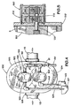
- Figure 3 illustrates a perspective view of a second embodiment of the present invention operative for the injection of a second fluid;
- Figure 4 illustrates a top view of the embodiment illustrated in Figure 3;
- Figure 5 illustrates a side, cross sectional view of a third embodiment of the present invention;
- Figure 6 illustrates a side, cross sectional view of a helical gear pump;
- Figure 7 illustrates an exploded view of the helical pump illustrated in Figure 6;
- Figure 8 illustrates a perspective, assembly.view of a fourth embodiment of the invention utilizing an impeller;
- Figure 9 illustrates a cross section of an impeller as it may be used with the embodiment of Figure 8; and
- Figure 10 illustrates yet another embodiment of the invention.
-
- One embodiment of the pumping system of the present invention may be seen reference to Figures 1 and 1A.
- As illustrated, the
pumping system 2 includes aflow meter 4 to which is mounted ametering pump 40 whereflow meter 4 includes ahousing 13, afluid inlet port 18 and afluid outlet 17. As intended by the present invention, flow meter broadly means a device which has at least one movable element, and the movable element can be moved when fluid is directed through the device. In the embodiment shown in Figures 1 - 1A, theflow meter 4 is a gear-type flow meter, as more fully described below. - In the illustrated embodiment, the
fluid inlet port 18 of theflow meter 4 is connected to afluid conduit 20. More specifically, in one presently preferred embodiment,conduit 20 includes an angular threadedconnector 18 which can rotate relative to said conduit, and the connector can be engaged with threads that are formed oninlet port 18. In turn,conduit 20 is situated in fluid communication with a water supply or other source offluid 19. It is to be understood thatconduit 20 can be connected to a water supply by any suitable means known in the art, e.g., by connectingconduit 20 to a fitting or nozzle that is in turn in fluid communication with a water supply. - The
housing 13 offlow meter 4 comprises atop wall 7, abottom wall 11 and aside wall 14 where each of the aforereferenced elements are adapted to be combined to form a substantially fluid tight unit. Typically,housing 13 includes some sort of access means, e.g. an access plate (not shown), to allow for inspection, repair and replacement of the internal components offlow meter 4. - In accordance with the present invention,
flow meter 4 includes one or more rotational elements which, in the embodiment shown in Figures 1 - 2, include afirst gear 24 and asecond gear 25 which rotate when the pressurized first fluid passes from theinlet 18 port to theoutlet port 17. - By reference to Figure 2,
gears internal cavity 23 defined byhousing 13. In some embodiments,gears inlet 18 rotates gears 24 and 25, thereby moving inserts past a point on thehousing 13, which contains means to detect the rotation of said insert. The frequency of this rotation may then be monitored to determine a flow rate. - In the embodiment illustrated in Figures 1 - 2,
metering pump 40 includes ahousing 41 defining aninternal cavity 49 in which are disposed a pair of intermeshing,counter rotating rotors Housing 41 includes asidewall 43, abottom wall 45 and atop wall 47, the combination adapted to be sealed to form a fluid tight compartment defining aninlet 50 and anoutlet 52, whereinlet 50 is disposed in fluid communication with areservoir 51 of a second fluid viaconduit 55. - In some embodiments, the
bottom wall 45 ofpump 40 may comprise thetop wall 7 offlow meter 4. In such a fashion, economy of construction may be observed. - By reference to Figures 1A, 6 and 7, it is desired that
rotors inlet 50 tooutlet 52. It may be desirable to utilize a helical tooth pattern such as that disclosed in U.S. Patent No. 5,415,041, the disclosure of which is herein incorporated by reference. For example, it may also be desirable to adopt a herringbone or straight tooth pattern to advance the objects of the invention. - By reference to Figures 6 and 7,
rotors Top wall 47 preferably comprises a cover to close thecavity 49 by fitting on a machined face of saidhousing 41 which is bolted in place withbolts 42 which extend throughopenings 63 ofcover 48 into alignedreceivers 65in.housing 41. - The buildup of deposits, e.g., calcium and precipitants from the additive solution, is a major cause for premature failure of cavity gear pumping systems. In some applications therefore, it may be desirable to utilize a metering pump housing which defines a close tolerance between
rotors pump outlet 52, thewalls defining cavity 49 and thepump inlet 50. In such a fashion, any deposits collecting about theinlet 50 oroutlet 52 are continuously sheered off byrotors pump 40. - In the embodiment illustrated in Figures 1 and 2, a connecting
element 30, e.g., a spline, is coupled tofirst rotor 25 offlow meter 4 and extends throughflow meter housing 13 into operative engagement with therotor 44 ofpump 40. In such a fashion, the rotation ofgear 24 as induced by the flow of the first fluid from theinlet 18 tooutlet 17 rotates thefirst rotor 44 and hencesecond rotor 46. The counter rotation ofrotors housing 41, thereby inducing fluid flow of the second fluid fromreservoir 51 throughconduit 55 intoinlet 50 and ultimately throughoutlet 52. - The coupling of
rotor 25 torotor 44 ofpump 40 allows for the metered input of the additive second fluid based on the flow valve of the fluid as dictated by the rotation ofrotors rotors rotors spline 30 may be formed to include a manually adjustable gear down assembly (not shown) to allow the ratio of the additive fluid to be altered. - By reference to Figures 1A and 2, in one aspect of the invention, pump 40 may be provided with priming means which comprises a
piston 86 slidably situated in abore 89 which is disposed in fluid communication withcavity 23 offlow meter 4 via access bore 95. Reciprocation ofpiston 86 inbore 89 allows the first fluid, e.g. water, to pass through bore 89 intocavity 49, thereby primingpump 40. - It is contemplated that it may be desirable in some situations to introduce the additive fluid downstream of
flow meter 4. In other applications, however, thepump outlet 52 may be disposed upstream ofmeter 4 or concomitant withflow meter outlet 17. - A second embodiment of the present invention may been seen by reference to Figures 3 - 4 in which is illustrated a
flow meter 100 of the general configuration as described above in relation to the embodiment of Figures 1 and 2, wheresuch flow meter 100 includes a first 102 and second 104 rotational element rotatingly disposed within aninternal cavity 106 defined within ahousing 105 which also includes aninlet 108 and anoutlet 110.Inlet 108 is disposed in fluid communication with a first source of fluid, e.g., water, through aconventional conduit 113 or other similar fluid flow member.Outlet 110 is likewise coupled to aconduit 115, as illustrated. - A
first metering pump 140 and asecond metering pump 160 are joined to flowmeter 100 in a similar manner to that described in relation to the embodiment of Figures 1 and 2. In this connection, one or both of first 140 andsecond pumps 160 may share a common wall withflow meter 100. Alternatively, either or both of first and second pumps may be formed integrally with the flow meter in a common housing with means provided for the separation of fluid flow. Still alternatively, first or second pumps may be raised or separated fromflow meter 100 as long as means are provided for the translation of the rotation of the rotational element(s) offlow meter 100 to said first and second pumps. This later arrangement may be helpful, for example, where it is desirable to remove one or more metering pumps from exposure from the heat of the primary fluid passing throughflow meter 100. Such an arrangement, may also be helpful when there exists space and design concerns. This design also provides an air gap to separate the source of drive water and the chemical being pumped. - Each of metering pumps 140 and 160 include, in the example of the
first pump 140, ahousing 122 defining aninternal cavity 123 and aninlet 125 and anoutlet 126, where saidinlet 125 is coupled to a second source offluid 137 by aconduit 129. In this embodiment, at least onerotational element 131 is rotatably disposed incavity 123 such that the rotation of saidelement 131 induces fluid flow throughinlet 125 andoutlet 126. - A connecting
element 120, e.g., a spline, is coupled to one or both ofrotational elements second pumps inlet 108 tooutlet 110 offlow meter 100 rotates first and secondrotational elements second pumps pumps reservoirs fluid inlets outlets valve 91 andcommon flow passage 80. In the embodiment illustrated in Figure 4, additive second and third fluids are introduced to the fluid stream throughhousing 105. Alternatively, one or more of the additive fluids may be introduced in theoutflow conduit 115 as illustrated in Figure 3. - In some applications, it may be desirable to include means to divert at least a portion of an additive fluid back to the fluid reservoir. Such reticulation may be important, for example, when the additive fluid is prone to settling. By reference to Figure 4, a
valve 91 may be disposed inoutlet conduit 80 such that upon partial opening of valve 91 a portion of the additive fluid is diverted back to the fluid reservoir. - Yet another embodiment of the present invention may be seen by reference to Figure 5 in which is illustrated a
flow meter 150, afirst pump 170 and asecond pump 190.Flow meter 150 is configured in much the same fashion as described above in relation to other embodiments and may adopt a variety of configurations. It is desired, however, thatmeter 150 include a fluid tight housing defining an inlet and an outlet, where at least onerotor element 155 is disposed therebetween. Similarly, pumps 170 and 190 may also adopt a number of configurations involving the use of at least rotational element which is coupled toelement 155. In this connection, it is contemplated that one or both ofpumps pumps flow meter 150. - In the illustrated embodiment, pumps 170 and 190 are arranged in a vertical or "stacked" relationship with respect to one another as to share a common interconnecting element or
spline 175. In such a fashion, the rotation of the rotational element offlow meter 150 results in the rotation of rotors in each ofpumps pumps meter 150. Alternatively, acompound spline 175 may be employed which allows for the selective adjustment of the rotation of one or both ofpumps a-vis metering pump 150. - The immediately aforedescribed embodiment may be desirable due to space constraints or design limitations.
- Yet another embodiment of the invention may be seen by reference to Figs. 8 and 9 in which is illustrated a
flow meter 200 which includes ahousing 202, afluid inlet port 204 and afluid outlet 206, as described previously in relation to other embodiments.Housing 202 itself comprises atop wall 211, abottom wall 209 and aside wall 202. Consistent with prior embodiments,flow meter 200 includes one or more rotational elements 214 (as shown in phantom) which rotate about shafts and include anextended spline 215 which extends outsidehousing 202. In the illustrated embodiment,spline 215 includes a flat 216 to aid in engagingpump 230, as will be described below. - By reference to Figures 8-9, pump 230 includes a
housing 232 which is generally circular in configuration and which defines a substantiallycircular bore 239, afluid inlet 240 and an outlet 242.Bore 239 is receivable to animpeller 234 which is adapted to rotate about ahub 238. It is contemplated thathub 238 includes a fixed shaft engageable withspline 215 so as to transfer the rotation of spline to impeller 234 so as to pull fluid frominlet 240 through outlet 242. - As illustrated,
impeller 234 is eccentrically disposed inbore 239, which eccentricity is adjustable depending on desired flow rates.Housing 232 includes anadjustment flange 260 which includes apivot aperture 262 about whichhousing 232 may be pivoted in a plane coplanar with the plane described byhousing top 211. The pivot ofhousing 232 serves to distort the shape ofimpeller 234 so as to increase or decrease the quantity of fluid moved through saidpump 230. In this connection,impeller 234 is preferably made from a pliable compound,e.g. rubber, which allows resilient deformation.Impeller 234 itself defines a number of fins which will be familiar to those skilled in the art. - It is contemplated that the aforedescribed adjustment to
impeller 234 may be made manually and gauged about gradations scored ontop 207. Alternately, a flow gauge (not shown) may be situated in the outflow line (not shown) and manual adjustments made from this flow gauge. Still alternately, pump 230 may be remotely adjusted, e.g. by a stepper motor, to achieve a desired and preprogrammed flow rate. In the instance of manual adjustment, pumphousing 232 may be secured tometer housing 202 about a particular orientation by ascrew 250, as illustrated. - Fluid metered through
pwnp 230 need not be necessarily introduced intoflow meter 200, tooutlet 206 oroutlet line 213 immediately downstream fromoutlet 206. Instead, the metered additive may be carried in aseparate line 243 which may parallelwater outlet line 209, wherelines - Still another embodiment of the invention may be seen by reference to Figure 10 in which is illustrated a
flow meter 300 defining ahousing 302 and at least one interior metering element which is rotated about the introduction of fluid throughmeter 300 in a manner consistent with that described above. In the illustrated embodiment, at least one of the rotatable elements includes aspline 304 which extends beyondhousing 302 and is coupled to acam wheel 307 which in turn is coupled to a crank 309 in a manner familiar to those skilled in the art.Crank 309 is in turn coupled to ametering pump 312 of a design generally disclosed and claimed in U.S. Patent No. 4,558,715. - In such a fashion, the introduction of water into
meter 300 turns at least one rotatable element which in turn acts upon crank 309 and pump 312 to induce a metered flow of fluid, e.g. medication or chemicals. The amount of fluid introduced throughpump 312 may be adjusted in a conventional fashion as disclosed in Applicant's prior patents, Patent Nos. 4,809,731 and 4,558,715. - Although particular detailed embodiments of the apparatus and method have been described herein, it should be understood that the invention is not restricted to the details of the preferred embodiment.
Claims (4)
- Apparatus for metering a predetermined amount of an additive liquid into a fluid stream, the apparatus having a flow meter (4) with a fluid stream inlet port (18) and a fluid stream outlet port (17), a rotatable element (24,25) that rotates at a selective rate of rotation based on the quantity of fluid flowing from said inlet port (18) to said outlet port (17); a metering pump (40) operably coupled to the rotatable element of the flow meter (4) and having an additive liquid inlet (50) and an additive liquid outlet (52); the flow meter outlet (17) and the additive liquid outlet (52) of the metering pump being in fluid communication, characterised in that:the metering pump (40) is provided with a priming means comprising a piston (86) in a bore (89) disposed in fluid communication with a cavity (23) in the flow meter (4) via an access bore (95) such that reciprocation of the piston (86) in the bore (89) allows fluid to pass through the bore to prime the metering pump.
- The apparatus of claim 1 wherein the metering pump (40) is coupled to the rotatable element (24,25) of the flow meter by a shaft (30).
- The apparatus of claim 1 or claim 2 wherein the rotatable element comprises first and second gears (24,25) mounted in comeshing relationship.
- The apparatus of claim 3 wherein the gears (24,25) are of a double helical configuration.
Applications Claiming Priority (2)
| Application Number | Priority Date | Filing Date | Title |
|---|---|---|---|
| US327201 | 1999-06-06 | ||
| US09/327,201 US6357466B1 (en) | 1999-06-07 | 1999-06-07 | Pumping system for the injection of measured quantities of fluid into a fluid stream |
Publications (3)
| Publication Number | Publication Date |
|---|---|
| EP1061426A2 EP1061426A2 (en) | 2000-12-20 |
| EP1061426A3 EP1061426A3 (en) | 2002-07-10 |
| EP1061426B1 true EP1061426B1 (en) | 2004-03-03 |
Family
ID=23275556
Family Applications (1)
| Application Number | Title | Priority Date | Filing Date |
|---|---|---|---|
| EP00112172A Expired - Lifetime EP1061426B1 (en) | 1999-06-06 | 2000-06-06 | Pumping system for the injection of measured qualities of fluid into a fluid stream |
Country Status (4)
| Country | Link |
|---|---|
| US (2) | US6357466B1 (en) |
| EP (1) | EP1061426B1 (en) |
| CA (1) | CA2311098C (en) |
| DE (1) | DE60008631T2 (en) |
Families Citing this family (13)
| Publication number | Priority date | Publication date | Assignee | Title |
|---|---|---|---|---|
| US8303277B2 (en) * | 2002-11-21 | 2012-11-06 | International Dispensing Corporation | Blending pump assembly |
| US7131826B1 (en) | 2002-11-21 | 2006-11-07 | International Dispensing Corporation | Blending pump assembly |
| US7131454B2 (en) * | 2003-05-16 | 2006-11-07 | Dosmatic, U.S.A. Inc. | Piston sealing mechanism for liquid additive injection pump |
| US20090042464A1 (en) * | 2005-04-11 | 2009-02-12 | Ocor Corporation | Water jet propulsion system |
| US8316874B2 (en) * | 2008-04-29 | 2012-11-27 | Roper Pump Company | Pressure plenum flow divider |
| MX339610B (en) * | 2010-01-06 | 2016-05-31 | Puricore Inc | Method of injecting solution into a misting line. |
| CN102059062A (en) * | 2010-11-26 | 2011-05-18 | 上海金盾消防安全设备有限公司 | Fluid-driving multi-medium proportional mixing system |
| CN104142164A (en) * | 2013-05-10 | 2014-11-12 | 罗美特(上海)自动化仪表有限公司 | Gas Roots flowmeter |
| ES2459841B1 (en) * | 2014-03-17 | 2014-12-09 | Aurep Dos, S.L. | Device for measuring the flow of an incompressible fluid with a driving means |
| US9725297B2 (en) * | 2014-08-28 | 2017-08-08 | Ecolab Usa Inc. | Chemical product dispensing independent of drive fluid flow rate |
| CA3017568A1 (en) * | 2016-04-12 | 2017-10-19 | Nestec S.A. | A liquid pumping device comprising a gear pump for beverage dispenser |
| WO2020006105A1 (en) | 2018-06-29 | 2020-01-02 | Ecolab Usa Inc. | Chemical product dispensing using a fluid drive and return home interface |
| CN109966982A (en) * | 2019-04-26 | 2019-07-05 | 嘉施利(铁岭)化肥有限公司 | A kind of blending fertile finely mixing system and its blending method |
Family Cites Families (20)
| Publication number | Priority date | Publication date | Assignee | Title |
|---|---|---|---|---|
| USRE16406E (en) * | 1926-08-24 | A cobpobaxioh | ||
| US1103053A (en) * | 1911-01-09 | 1914-07-14 | Karl Kiefer | Fluid pump or motor. |
| US2567997A (en) * | 1945-06-05 | 1951-09-18 | Albert J Granberg | Proportioner |
| US2543941A (en) * | 1946-03-06 | 1951-03-06 | Hale Fire Pump Co | Proportioning device |
| US2564306A (en) * | 1948-08-03 | 1951-08-14 | Simmonds Aerocessories Inc | Apparatus for proportionally blending liquids |
| US2611323A (en) * | 1948-11-30 | 1952-09-23 | Harold D Digney | Pump |
| US3054417A (en) * | 1956-05-07 | 1962-09-18 | Corvisier Louis Rene | Apparatus for mixing liquids in a constant proportion |
| FR1281877A (en) * | 1960-07-08 | 1962-01-19 | Method for the constant metering of a mixture of liquids circulating in a hydraulic circuit and metering device for its implementation | |
| US3213873A (en) * | 1961-05-23 | 1965-10-26 | Carl F Jensen | Self-powered fluid treater |
| US3575535A (en) * | 1969-04-21 | 1971-04-20 | Frederick H Bickar | Additive proportioning, positive displacement, pumplike device |
| US3937241A (en) | 1973-11-29 | 1976-02-10 | Philippe Cloup | Device for injecting an adjuvant into a liquid |
| FR2303182A1 (en) | 1975-03-05 | 1976-10-01 | Cloup Jean | SUCTION VALVE CONTROL FOR DOSING PUMP |
| US4328824A (en) * | 1979-12-10 | 1982-05-11 | General Electric Company | Flow divider with plural metering gears, unrestrained spacers there-between and lubricated end roller bearings |
| US4558715A (en) | 1984-05-16 | 1985-12-17 | Kowatachi International, Ltd. | Apparatus for injecting measured quantities of liquid into a fluid stream |
| US4809731A (en) | 1985-01-17 | 1989-03-07 | Frank A. Walton | Liquid injection apparatus having an external adjustor |
| FR2607194A1 (en) * | 1986-11-25 | 1988-05-27 | Baugier Jean Pierre | Autonomous device for injecting an additive in adjustable proportions into a liquid flow |
| DE3939780A1 (en) * | 1989-12-01 | 1991-06-06 | Wilhelm Haeberle | Heat pump or refrigeration circuit - has crank used to operate offset piston providing asymmetrical movement |
| US5156301A (en) * | 1990-12-17 | 1992-10-20 | Imi Cornelius Inc. | Constant ratio post-mix beverage dispensing valve |
| US5269443A (en) | 1992-11-03 | 1993-12-14 | Condor, Inc. | Dosing pump for blending two liquids |
| US5415041A (en) | 1994-01-24 | 1995-05-16 | Flowdata, Inc. | Double helical flowmeter |
-
1999
- 1999-06-07 US US09/327,201 patent/US6357466B1/en not_active Expired - Fee Related
-
2000
- 2000-06-02 CA CA002311098A patent/CA2311098C/en not_active Expired - Fee Related
- 2000-06-06 DE DE60008631T patent/DE60008631T2/en not_active Expired - Lifetime
- 2000-06-06 EP EP00112172A patent/EP1061426B1/en not_active Expired - Lifetime
-
2001
- 2001-10-02 US US09/969,469 patent/US6431198B2/en not_active Expired - Fee Related
Also Published As
| Publication number | Publication date |
|---|---|
| US20020017320A1 (en) | 2002-02-14 |
| DE60008631T2 (en) | 2004-07-29 |
| CA2311098C (en) | 2006-04-18 |
| US6431198B2 (en) | 2002-08-13 |
| EP1061426A2 (en) | 2000-12-20 |
| DE60008631D1 (en) | 2004-04-08 |
| US6357466B1 (en) | 2002-03-19 |
| EP1061426A3 (en) | 2002-07-10 |
| CA2311098A1 (en) | 2000-12-07 |
Similar Documents
| Publication | Publication Date | Title |
|---|---|---|
| US6357466B1 (en) | Pumping system for the injection of measured quantities of fluid into a fluid stream | |
| US9440836B2 (en) | Rotary cabonator | |
| CN102138007B (en) | reverse osmosis equipment | |
| US3824041A (en) | Positive displacement liquid pump | |
| CN102858436B (en) | Reverse osmosis system | |
| US3821963A (en) | Liquid proportioning apparatus | |
| KR102271066B1 (en) | Proportioner for Mixing Extinguishing Agents with Constant Mixing Ratio | |
| US4395130A (en) | Interconnected pumping mechanism | |
| US3286933A (en) | Duplex chemical feeding system | |
| US8303277B2 (en) | Blending pump assembly | |
| US6533557B1 (en) | Positive displacement pump | |
| US3390638A (en) | Variable proportioning metering pump | |
| US7404705B2 (en) | Blending pump assembly | |
| US2671462A (en) | Apparatus for proportioning the delivery of liquids | |
| US20150034537A1 (en) | Automatic Drinking Water Enhancement Apparatus | |
| US10047735B2 (en) | Mixing pump | |
| EP3012452A1 (en) | Device for setting a volumetric flow rate ratio and fluid treatment apparatus | |
| US3479957A (en) | Positive displacement gear type pump | |
| CN214577670U (en) | Uninterrupted water supply plunger pump system | |
| US6299422B1 (en) | Fluid pump with a flexible toothed belt | |
| WO2008030228A1 (en) | Blending pump assembly | |
| CN109630726A (en) | Liquid fraction part flow arrangement | |
| AU718744C (en) | Fluid pump with a flexible toothed belt | |
| CN115324893A (en) | Oil-gas mixed transportation skid-mounted device special for oil field | |
| KR200369153Y1 (en) | waterwheel type fixed quantity supply instrument |
Legal Events
| Date | Code | Title | Description |
|---|---|---|---|
| PUAI | Public reference made under article 153(3) epc to a published international application that has entered the european phase |
Free format text: ORIGINAL CODE: 0009012 |
|
| AK | Designated contracting states |
Kind code of ref document: A2 Designated state(s): AT BE CH CY DE DK ES FI FR GB GR IE IT LI LU MC NL PT SE |
|
| AX | Request for extension of the european patent |
Free format text: AL;LT;LV;MK;RO;SI |
|
| PUAL | Search report despatched |
Free format text: ORIGINAL CODE: 0009013 |
|
| AK | Designated contracting states |
Kind code of ref document: A3 Designated state(s): AT BE CH CY DE DK ES FI FR GB GR IE IT LI LU MC NL PT SE |
|
| AX | Request for extension of the european patent |
Free format text: AL;LT;LV;MK;RO;SI |
|
| 17P | Request for examination filed |
Effective date: 20020816 |
|
| 17Q | First examination report despatched |
Effective date: 20020926 |
|
| AKX | Designation fees paid |
Designated state(s): DE ES FR GB |
|
| GRAH | Despatch of communication of intention to grant a patent |
Free format text: ORIGINAL CODE: EPIDOS IGRA |
|
| GRAS | Grant fee paid |
Free format text: ORIGINAL CODE: EPIDOSNIGR3 |
|
| GRAA | (expected) grant |
Free format text: ORIGINAL CODE: 0009210 |
|
| AK | Designated contracting states |
Kind code of ref document: B1 Designated state(s): DE ES FR GB |
|
| REG | Reference to a national code |
Ref country code: GB Ref legal event code: FG4D |
|
| REG | Reference to a national code |
Ref country code: IE Ref legal event code: FG4D |
|
| REF | Corresponds to: |
Ref document number: 60008631 Country of ref document: DE Date of ref document: 20040408 Kind code of ref document: P |
|
| PG25 | Lapsed in a contracting state [announced via postgrant information from national office to epo] |
Ref country code: ES Free format text: LAPSE BECAUSE OF FAILURE TO SUBMIT A TRANSLATION OF THE DESCRIPTION OR TO PAY THE FEE WITHIN THE PRESCRIBED TIME-LIMIT Effective date: 20040614 |
|
| ET | Fr: translation filed | ||
| PLBE | No opposition filed within time limit |
Free format text: ORIGINAL CODE: 0009261 |
|
| STAA | Information on the status of an ep patent application or granted ep patent |
Free format text: STATUS: NO OPPOSITION FILED WITHIN TIME LIMIT |
|
| 26N | No opposition filed |
Effective date: 20041206 |
|
| REG | Reference to a national code |
Ref country code: IE Ref legal event code: MM4A |
|
| PGFP | Annual fee paid to national office [announced via postgrant information from national office to epo] |
Ref country code: DE Payment date: 20130529 Year of fee payment: 14 Ref country code: GB Payment date: 20130605 Year of fee payment: 14 |
|
| PGFP | Annual fee paid to national office [announced via postgrant information from national office to epo] |
Ref country code: FR Payment date: 20130624 Year of fee payment: 14 |
|
| REG | Reference to a national code |
Ref country code: DE Ref legal event code: R119 Ref document number: 60008631 Country of ref document: DE |
|
| GBPC | Gb: european patent ceased through non-payment of renewal fee |
Effective date: 20140606 |
|
| REG | Reference to a national code |
Ref country code: FR Ref legal event code: ST Effective date: 20150227 |
|
| REG | Reference to a national code |
Ref country code: DE Ref legal event code: R119 Ref document number: 60008631 Country of ref document: DE Effective date: 20150101 |
|
| PG25 | Lapsed in a contracting state [announced via postgrant information from national office to epo] |
Ref country code: DE Free format text: LAPSE BECAUSE OF NON-PAYMENT OF DUE FEES Effective date: 20150101 |
|
| PG25 | Lapsed in a contracting state [announced via postgrant information from national office to epo] |
Ref country code: GB Free format text: LAPSE BECAUSE OF NON-PAYMENT OF DUE FEES Effective date: 20140606 Ref country code: FR Free format text: LAPSE BECAUSE OF NON-PAYMENT OF DUE FEES Effective date: 20140630 |