EP1061398A2 - Multi-beam scanning optical system and image forming apparatus using the same - Google Patents
Multi-beam scanning optical system and image forming apparatus using the same Download PDFInfo
- Publication number
- EP1061398A2 EP1061398A2 EP00112583A EP00112583A EP1061398A2 EP 1061398 A2 EP1061398 A2 EP 1061398A2 EP 00112583 A EP00112583 A EP 00112583A EP 00112583 A EP00112583 A EP 00112583A EP 1061398 A2 EP1061398 A2 EP 1061398A2
- Authority
- EP
- European Patent Office
- Prior art keywords
- optical system
- light beams
- scanning direction
- scanned
- main
- Prior art date
- Legal status (The legal status is an assumption and is not a legal conclusion. Google has not performed a legal analysis and makes no representation as to the accuracy of the status listed.)
- Granted
Links
Images





Classifications
-
- H—ELECTRICITY
- H04—ELECTRIC COMMUNICATION TECHNIQUE
- H04N—PICTORIAL COMMUNICATION, e.g. TELEVISION
- H04N1/00—Scanning, transmission or reproduction of documents or the like, e.g. facsimile transmission; Details thereof
- H04N1/04—Scanning arrangements, i.e. arrangements for the displacement of active reading or reproducing elements relative to the original or reproducing medium, or vice versa
- H04N1/19—Scanning arrangements, i.e. arrangements for the displacement of active reading or reproducing elements relative to the original or reproducing medium, or vice versa using multi-element arrays
- H04N1/191—Scanning arrangements, i.e. arrangements for the displacement of active reading or reproducing elements relative to the original or reproducing medium, or vice versa using multi-element arrays the array comprising a one-dimensional [1D] array
- H04N1/1911—Simultaneously or substantially simultaneously scanning picture elements on more than one main scanning line, e.g. scanning in swaths
-
- G—PHYSICS
- G02—OPTICS
- G02B—OPTICAL ELEMENTS, SYSTEMS OR APPARATUS
- G02B26/00—Optical devices or arrangements for the control of light using movable or deformable optical elements
- G02B26/08—Optical devices or arrangements for the control of light using movable or deformable optical elements for controlling the direction of light
- G02B26/10—Scanning systems
- G02B26/12—Scanning systems using multifaceted mirrors
- G02B26/123—Multibeam scanners, e.g. using multiple light sources or beam splitters
-
- H—ELECTRICITY
- H04—ELECTRIC COMMUNICATION TECHNIQUE
- H04N—PICTORIAL COMMUNICATION, e.g. TELEVISION
- H04N1/00—Scanning, transmission or reproduction of documents or the like, e.g. facsimile transmission; Details thereof
- H04N1/04—Scanning arrangements, i.e. arrangements for the displacement of active reading or reproducing elements relative to the original or reproducing medium, or vice versa
- H04N1/113—Scanning arrangements, i.e. arrangements for the displacement of active reading or reproducing elements relative to the original or reproducing medium, or vice versa using oscillating or rotating mirrors
- H04N1/1135—Scanning arrangements, i.e. arrangements for the displacement of active reading or reproducing elements relative to the original or reproducing medium, or vice versa using oscillating or rotating mirrors for the main-scan only
Definitions
- This invention relates to a multi-beam scanning optical system using a light source having a plurality of light emitting sections such as a semiconductor laser array and adapted to high speed high density recording.
- a multi-beam scanning optical system according to the invention can suitably be used for an image forming apparatus such as a laser beam printer or a digital copying machine.
- Multi-beam scanning optical systems using a light source having a plurality of light emitting sections such as a semiconductor laser array have been proposed to meet the demand.
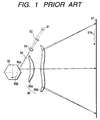
- FIG. 1 of the accompanying drawings is a schematic cross sectional view of a known multi-beam scanning optical system taken along the main-scanning direction.
- a plurality of light beams emitted from so many semiconductor lasers (or a semiconductor laser array) 91 are substantially collimated by a collimator lens 92 and then converged only in the sub-scanning direction by a cylindrical lens 94 having a predetermined refractive power only in the sub-scanning direction.
- the light beams are then trimmed by an aperture stop 93 and focussed on or near a deflecting plane (reflecting plane) 95a of an optical deflector 95, which is a rotary polygon mirror, to produce a substantially linear image extending in the main-scanning direction. Then, the light beams deflected/reflected by the deflecting plane 95a of the polygon mirror 95 that is rotating at a predetermined angular velocity in the sense of arrow 95b in FIG.
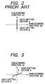
- FIGS. 2 and 3 are schematic illustrations of the arrangement of light emitting sections of the light source of a multi-beam scanning optical system.
- reference symbols A and B denote respective light emitting sections and reference symbol M denote the main-scanning direction whereas reference symbol S denotes the sub-scanning direction.
- the scanning lines on the surface of the photosensitive drum produce large intervals in the sub-scanning direction that are by far greater than the values required for achieving a desired recording density.
- the light emitting sections A and B are arranged on a line that forms a non-zero angle ⁇ with the sub-scanning direction (S) as shown in FIG. 3.
- the intervals separating the scanning lines on the surface of the photosensitive drum can be accurately regulated to achieve the desired recording density by selecting an appropriate value for angle ⁇ .
- the light emitting sections of the light source are arranged at respective positions that vary from each other in terms of both the main-scanning direction (M) and the sub-scanning direction (S) that is perpendicular relative to the main-scanning direction (M).
- the angle (of incidence) ⁇ between the light beams striking the surface 97 of the photosensitive drum and the normal to the surface 97 of the photosensitive drum is made equal to a predetermined value in the sub-scanning direction in known multi-beam scanning optical systems as shown in FIG. 4.
- FIG. 4 is a schematic cross sectional view of a known multi-beam scanning optical system taken along the sub-scanning direction. Note that, in FIG. 4, the components same as those of FIG. 1 are denoted respectively by the same reference symbols and will not be described any further.
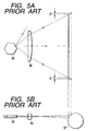
- FIGS. 5A and 5B are schematic cross sectional view of a principal portion of a known multi-beam scanning optical system and a photosensitive drum shown to illustrate the problem thereof.
- reference symbols 95 and 96 respectively denote a polygon mirror and a scanning lens system and reference symbol D denotes the displacement of beam spots.
- Japanese Patent Application Laid-Open Nos. 5-333281 and 9-197308 describes an arrangement for reducing the displacement of focal point in the main-scanning direction by making the angle between the light beams striking the surface of the photosensitive drum and the normal to the surface of the photosensitive drum in the sub-scanning direction smaller than a predetermined value.
- Japanese Patent Application Laid-Open No. 9-197308 describes an arrangement for reducing the displacement of focal point in the main-scanning direction by arranging the imaging optical system eccentrically and regulating the extent of the eccentricity.
- none of the proposed multi-beam scanning optical systems including those described in the above cited patent documents can satisfy both the requirement of reducing the displacement of focal point in the main-scanning direction and that of forming an excellent (spot-shaped) image.
- Japanese Patent Application Laid-Open No. 5-333281 describes an arrangement of making the angle between the light beams striking the surface of the photosensitive drum and the normal to the surface of the photosensitive drum in the sub-scanning direction smaller than a predetermined value.
- this arrangement can only reduce the displacement of focal point in the main-scanning direction to make it less remarkable.
- the method proposed in Japanese Patent Application Laid-Open No. 5-333281 cannot dissolve the problem of displacement of focal point in the main-scanning direction.
- Japanese Patent Application Laid-Open No. 9-197308 describes an arrangement for reducing the displacement of focal point in the main-scanning direction by arranging the imaging optical system eccentrically and regulating the extent of the eccentricity.
- the imaging optical system is arranged eccentrically, the spot-shaped image formed on the surface of the photosensitive drum can easily become deformed to make it difficult to realize a high quality and high speed image recording.
- a multi-beam scanning optical system that can effectively reduce the displacement of focal point in the main-scanning direction and produce a high quality image.
- a multi-beam scanning optical system according to the invention can suitably be used for an image forming apparatus to produce high quality images at high speed.
- a multi-beam scanning optical system comprising:
- the plurality of light beams striking the surface to be scanned being inclined in the sub-scanning direction so as to make their principal rays to show a non-zero angle relative to the normal to the surface to be scanned, thereby producing a positional displacement among the focal points of the light beams on the surface to be scanned in a first direction parallel to the main-scanning direction, the convergent or divergent light beams entering the third optical system producing a relative positional displacement among the focal points thereof on the surface to be scanned in a second direction parallel to the main-scanning direction, the first direction and the second direction being opposite to each other.
- an image forming apparatus comprising:
- FIG. 6A is a schematic cross sectional view of a principal portion of Embodiment 1 of multi-beam scanning optical system according to to the invention and taken along the main-scanning direction.
- FIG. 7 is a schematic cross sectional view of a principal portion of the multi-beam scanning optical system of FIG. 6A taken along the sub-scanning direction.
- the components same as those of FIG. 6A are denoted respectively by the same reference symbols and will not be described repeatedly.
- reference symbol 1 denotes a light source.
- the light source 1 is a multi-semiconductor-laser (semiconductor laser array) comprising a plurality of light emitting sections (light emitting spots) A and B that are arranged in such a way that the line connecting them forms an angle with the sub-scanning direction.
- FIG. 6B shows the light emitting sections A and B of the light source 1 encircled and viewed in the direction of arrow E in FIG. 6A.
- M indicates the main-scanning direction while S indicates the sub-scanning direction.
- reference symbol 2 denotes a condensing lens operating as first optical system.
- the condensing lens 1 transforms the plurality of light beams emitted from the light source 1 into convergent (or divergent) beams of light.
- Reference symbol 4 in FIG. 6A denotes a cylindrical lens (cylinder lens) operating as second optical system.
- the cylindrical lens shows a predetermined refractive power only in the sub-scanning direction so that, after passing through the condensing lens 2, the light beams are focussed on the deflection surface 5a of rotary polygon mirror 5, which will be described hereinafter, to form linear images extending in a plane intersecting the optical axis along the sub-scanning direction.
- Reference symbol 3 in FIG. 6A denotes an aperture stop, which aperture stop 3 limits the width of the light beams that have passed through the cylindrical lens 4.
- reference symbol 5 denotes a polygon mirror operating as deflection means (optical deflector).
- the polygon mirror 5 is driven to rotate at a constant rate in the direction of arrow 5b by a drive means (not shown) such as a motor.
- Reference symbol 6 denotes an f ⁇ lens (scanning optical system) having an f ⁇ feature.
- the f ⁇ lens system 6 comprises a pair of f ⁇ lenses (first f ⁇ lens and second f ⁇ lens) 6a and 6b.
- the f ⁇ lens system 6 focusses the plurality of light beams deflected/reflected by the rotary polygon mirror 5 on the surface to be scanned 7. More specifically, the f ⁇ lens system establishes an optically conjugate relationship between the deflection surface 5a of the rotary polygon mirror 5 and the surface to be scanned 7 in a plane intersecting the optical axis along the sub-scanning direction.
- the surface to be scanned 7 is the surface (image carrying surface) of a photosensitive drum having its axis of rotation running in the main-scanning direction.
- Each of the pair of f ⁇ lenses 6a and 6b is typically a toric lens.
- at least one of the f ⁇ lenses has a non-spherical surface in a plane intersecting the optical axis along the main-scanning direction.
- Such an f ⁇ lens can be prepared by injection-molding using a plastic material and a metal mold.
- the light beams emitted from the light source (multi-semiconductor-laser) 1 are transformed into convergent beams of light by the condensing lens 2 before entering the cylindrical lens 4.
- the light beams entering the cylindrical lens 4 leave the lens 4 without being modified in the main-scanning section, i.e., the plane intersecting the optical axis along the main-scanning direction, and the quantity of light of the light beams is limited by the aperture stop 3 in that section.
- they are converged in the sub-scanning section, i.e., the plane intersecting the optical axis along the sub-scanning direction, and the quantity of light of the light beams is also limited by the aperture stop 3 in that section.
- the light beams form linear images extending in the main-scanning direction on the deflection surface 5a of the rotary polygon mirror 5.
- the plurality of light beams deflected/reflected by the deflection surface 5a of the rotary polygon mirror 5 are then focussed by the f ⁇ lens system 6 to produce respective images that are so many spots of light on the surface to be scanned (surface of the photosensitive drum) 7.
- the surface (surface of the photosensitive drum) 7 is scanned by the spots of light in the direction indicated by arrow 7b (main-scanning direction) in FIG. 6A as the rotary polygon mirror 5 is driven to rotate in the sense of arrow 5b in FIG. 6A.
- an image can be recorded on the surface to be scanned (surface of the photosensitive drum) 7 that operates as recording medium.
- the beams of light regularly reflected by the surface to be scanned (surface of the photosensitive drum) 7 are not returned to the optical system for the above described reason. More specifically, the light beams striking the surface to be scanned (surface of the photosensitive drum) 7 are inclined in the sub-scanning direction so as to make their principal rays to show a non-zero angle (of incidence) ⁇ relative to the normal to the surface to be scanned as shown in FIG. 7.
- the principal ray of the light beam forming spot A on the surface to be scanned (surface of the photosensitive drum) 7 and that of the light beam forming spot B on the surface are not parallel to each other in a rigorous sense of the word. Additionally, the position of the spot A and that of the spot B on the surface to be scanned (surface of the photosensitive drum) 7 are displaced relative to each other in the sub-scanning direction and hence the normals at the respective spots are not parallel relative to each other because the surface to be scanned is that of a drum.
- the light beams striking the surface to be scanned are "inclined in the sub-scanning direction so as to make their principal rays to show respective non-zero angles (of incidence) relative to the respective normals to the surface to be scanned".
- the light beams striking the surface to be scanned are regarded to be "inclined in the sub-scanning direction so as to make their principal rays to show a predetermined angle ⁇ relative to the normal to the surface to be scanned".
- FIG. 8 is a schematic cross sectional view of a principal portion of a multi-beam scanning optical system, illustrating two scanning lines being used on the surface to be scanned (surface of a photosensitive drum) 7 for parallel scanning.
- the main-scanning direction is expressed by the Y-axis while the sub-scanning direction along which the surface to be scanned (surface of the photosensitive drum) 7 is driven to move is expressed by the Z-axis and the normal to the surface to be scanned (surface of the photosensitive drum) 7 is expressed by the X-axis of an orthogonal coordinate system.
- FIG. 8 illustrates the light beams when a maximum angle of view is used for scanning. Assume that the angle formed by the principal rays of the light beams and the optical axis of the f ⁇ lens system 6 is ⁇ and the angle formed by the striking light beams and the X-Y plane is ⁇ under this condition.
- ⁇ X P ⁇ sin ⁇
- P the gap separating the scanning lines in the sub-scanning direction that are scanning the surface to be scanned (surface of the photosensitive drum) 7 simultaneously.
- ⁇ Y1 takes a negative value in FIG. 8.
- the displacement ⁇ Y1 takes a negative value in this embodiment, it is so arranged that the (maximum) positional displacement ⁇ Y2 in the main-scanning direction of each of the spots formed on the surface of the photosensitive drum 7 by the focussed light beams as a result of making convergent light beams enter the f ⁇ lens system 6 as will be described hereinafter takes a positive value.
- the positional displacement ⁇ Y1 takes a positive value unlike this embodiment, the positional displacement ⁇ Y2 is made to take a negative value.
- the angle (of incidence) ⁇ and the extent of convergence of the light beams entering the f ⁇ lens system 6 are so selected as to make the two positional displacement values offset each other.
- the two light beams emitted from the light emitting sections show respective angles of reflection that are different from each other as they are deflected/reflected by the rotary polygon mirror so that they are focussed on the surface to be scanned (surface of the photosensitive drum) to form respective spots that are separated from each other in the main-scanning direction.
- one of the light beams is emitted from the corresponding light emitting section with a predetermined time lag of ⁇ T as viewed from the other light beam emitted from the other light emitting section that operates as reference so that the two light beams may be focussed at a same spot on the surface to be scanned (surface of the photosensitive drum).
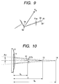
- FIG. 9 schematically illustrates this arrangement.
- the principal rays of two light beams are reflected by the deflection surface of the rotary polygon mirror at the side where a scanning operation is started.
- the light beam emitted from light emitting section A is reflected by the deflection surface 5a of the rotary polygon mirror in the direction of A1 in FIG. 9 and focussed on the surface to be scanned (surface of the photosensitive drum) 7 by an f ⁇ lens system 6 (not shown) before the emission of the other light beam.
- the other light beam emitted from light emitting section B is reflected by the deflection surface 5a' of the rotary polygon mirror in the direction of B1' in FIG. 9.
- the two beams are focussed at the same spot on the surface to be scanned (surface of the photosensitive drum) 7.
- the principal rays of the two light beams enter the f ⁇ lens system 6 with a same angle of incidence but at different points that are separated by a distance of ⁇ ys in the main-scanning direction after having been reflected by the respective deflection surfaces 5a and 5a' of the rotary polygon mirror because they are reflected by the rotary polygon mirror at respective position that are displaced from each other.
- the two light beams are substantially collimated when they enter the f ⁇ lens system 6, they are focussed at a same spot on the surface to be scanned (surface of the photosensitive drum) 7 regardless of the relative displacement ⁇ ys of their principal rays in the main-scanning direction.
- the two light beams are convergent when they enter the f ⁇ lens system 6, they are focussed at respective spots on the surface to be scanned (surface of the photosensitive drum) 7 that are displaced from each other in the main-scanning direction to reflect the relative displacement ⁇ ys of their principal rays in the main-scanning direction.
- FIG. 10 is a schematic view of a principal portion of the optical system of Embodiment 1, illustrating this phenomenon.
- reference symbol 6 denotes the f ⁇ lens system. If the distance between the rear principal plane 11 of the f ⁇ lens system 6 and the point of natural convergence 14 of a convergent light beam entering the f ⁇ lens system 6 is Sd, the focal length of the f ⁇ lens system 6 is f and the distance between the rear principal plane 11 of the f ⁇ lens system 6 and the point 12 where the convergent beam entering the f ⁇ lens system 6 is focussed by the latter (on the surface of the photosensitive drum) is Sk, they show a relationship defined by formula (3) below.
- 1 SK 1 Sd + 1 f
- ⁇ Y2 can be determined by formula (5) below.
- ⁇ Y2 shows a positive value in the direction of increasing the scanning width.
- ⁇ Y2 shows a positive value.
- FIG. 11 is a schematic illustration of a deflection surface of a rotary polygon mirror reflecting the principal rays of a pair of light beams at the side where a scanning operation is terminated.
- the light beam emitted from light emitting section A is reflected by the deflection surface 5a of the rotary polygon mirror in the direction of A1 in FIG. 11 and focussed on the surface to be scanned (surface of the photosensitive drum) 7 by an f ⁇ lens system 6 (not shown) before the emission of the other light beam .
- the other light beam emitted from light emitting section B is reflected by the deflection surface 5a' of the rotary polygon mirror in the direction of B1' in FIG. 11.
- the principal rays of the two beams are displaced by ⁇ ye from each other in the main-scanning direction when entering the f ⁇ lens system 6.
- the light beam B' emitted from the light emitting section B is displaced toward the optical axis of the f ⁇ lens system 6 relative to the light beam A' emitted from the light emitting section A both at the side where the scanning operation is started and at the side where the scanning optical is terminated so that consequently the span scanned by the light beam B' is shorter than the span scanned by the light beam A' on the surface to be scanned (surface of the photosensitive drum) 7 as shown in FIG. 12 that schematically illustrates a pair of scanning lines on the surface to be scanned (surface of the photosensitive drum).
- this embodiment is so devised that the positional displacement in the main-scanning direction of the spots of light formed respectively by a pair of focussed light beams that is produced when the principal rays of the pair of light beams striking the surface to be scanned (surface of the photosensitive drum) 7 are made to show a predetermined angle of ⁇ relative to the normal to the surface of the photosensitive drum 7 in the sub-scanning direction is directed reversely relative to and hence offset by the positional displacement in the main-scanning direction of the spots of light formed respectively by the pair of focussed light beams that is produced if the light beams are convergent when entering the f ⁇ lens system 6.
- optimal values are selected respectively for the angle (of incidence) ⁇ , the distance Sd between the rear principal plane 11 of the f ⁇ lens system 6 and the point of natural convergence 14 of a convergent light beam entering the f ⁇ lens system 6 and the distance Sk between the rear principal plane 11 of the f ⁇ lens system 6 and the point 12 where the convergent beam entering the f ⁇ lens system 6 is focussed by the latter (on the surface of the photosensitive drum). Then, as a result, the positional displacement of the spots of light formed by any two light beams in the main-scanning direction is substantially totally eliminated on the entire surface of the surface to be scanned (surface of the photosensitive drum) 7.
- the components of this embodiment are so selected that, if the positional displacement in the main-scanning direction of the spots of light formed respectively by a pair of focussed light beams that is produced when the principal rays of the pair of light beams striking the surface to be scanned (surface of the photosensitive drum) 7 are made to show a predetermined angle of ⁇ relative to the normal to the surface of the photosensitive drum 7 in the sub-scanning direction is ⁇ T1 and the positional displacement in the main-scanning direction of the spots of light formed on the surface of the photosensitive drum respectively by the pair of focussed light beams that are transformed into convergent light beams by making them to pass through an f ⁇ lens system 6 is ⁇ Y2, ⁇ Y1 and ⁇ Y2 are directed in opposite directions and satisfy the requirement of formula
- ⁇ Y1 and ⁇ Y2 are directed in opposite directions, they are prefixed respectively by positive and negative signs or vice versa. With this arrangement, the positional displacement of the spots of light formed by any two light beams in the main-scanning direction is corrected to an acceptable level on the entire surface of the surface to be scanned (surface of the photosensitive drum) 7 from the viewpoint of the quality of the image produced on the surface of the photosensitive drum 7.
- Tables 1 and 2 below show various characteristic values of Embodiment 1 of multi-beam scanning optical system according to the invention.
- operating wavelength ⁇ (nm) 780 polygon surface - first f ⁇ lens, first surface d1 41.78 thickness of first f ⁇ lens d2 9.50 first f ⁇ lens, second surface - second f ⁇ lens, first surface d3 7.13 thickness of second f ⁇ lens d4 8.60 second f ⁇ lens, second surface - surface to be scanned d5 189.74 first f ⁇ lens, refractive index Nlens1 1.52420 second f ⁇ lens, refractive index Nlens2 1.52420 f ⁇ lens, rear side principal plane - point of natural convergence Sd 1176.401 f ⁇ lens, rear side principal plane - focal point Sk 204.695 f ⁇ lens, focal length f 251.051 interval separating light emitting spots d 0.090 number of light emitting spots n 2 angle between light beams entering drum and normal to drum ⁇ 5.739 angle of
- the radius of curvature r' takes a value as determined by using symbols D 2u through B 10u as suffixed by u to correspond to the positive value of y, whereas the radius of curvature r' takes a value as determined by using symbols D 2l through B 10l as suffixed by l to correspond to the negative value of y.
- the positional displacement in the main-scanning direction of the spots of light formed by the convergent light beams focussed by the f ⁇ lens system 6 and the positional displacement in the main-scanning direction of the spots of light formed by the focussed light beams striking the surface of the photosensitive drum 7 and having their principal rays form a predetermined angle of ⁇ relative to the normal to the surface of the photosensitive drum 7 in the sub-scanning are made to completely offset and correct each other by appropriately selecting the positions of the light emitting sections A and B and the value of the angle ⁇ as shown in FIGS. 6A, 6B and 7.
- an image forming apparatus such as a laser beam printer or a digital copying machine comprising a multi-beam scanning optical system of this embodiment is adapted to provide a recording density of 600DPI
- the parameters P, ⁇ Y1 and ⁇ Y2 of formula (6) defining the above requirement will take the following values.
- the angle ⁇ formed by the light beams striking the surface to be scanned (surface of the photosensitive drum) 7 and the normal to the surface to be scanned in the sub-scanning direction, the distance Sd between the rear principal plane 11 of the f ⁇ lens system 6 and the point of natural convergence 14 of a convergent light beam entering the f ⁇ lens system 6 and the distance Sk between the rear principal plane 11 of the f ⁇ lens system 6 and the point 12 where the convergent beam entering the f ⁇ lens system 6 is focussed by the latter are optimally selected in this embodiment.
- an image forming apparatus comprising a multi-beam scanning optical system according to the invention is adapted to high speed, high density recording.
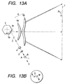
- FIG. 13A is a schematic cross sectional view of a principal portion of Embodiment 2 of multi-beam scanning optical system according to the invention and taken along the main-scanning direction as it is used in an image forming apparatus such as a laser beam printer or a digital copying machine.
- FIG. 14 is a schematic cross sectional view of a principal portion of the multi-beam scanning optical system shown in FIG. 13A and taken along the sub-scanning direction.
- FIGS. 13A and 14 the components same as those of FIGS. 6A and 7 are denoted respectively by the same reference symbols and will not be described any furhter.
- FIG. 13B is a schematic illustration of the arrangement of light emitting sections of the light source of Embodiment 2 of FIG. 13A. As in FIG. 6B, the light emitting sections A, B are encircled and viewed in the direction of arrow E in FIG. 13B. Note that, in FIG. 13B, M indicates the main-scanning direction and S indicates the sub-scanning
- Embodiment 2 differs from above described Embodiment 1 in terms of the angle ⁇ formed by the principal rays of the light beams striking the surface to be scanned (surface of the photosensitive drum) 7 and the normal to the surface to be scanned in the sub-scanning direction and hence the positions of the light emitting sections A and B. Otherwise, the optical effect of Embodiment 2 is substantially same as that of Embodiment 1.
- the angle ⁇ is located under the center line O running in the direction of the optical axis of the photosensitive drum as shown in FIG. 14 due to some necessary degree of freedom for the arrangement of the main body.
- the positional displacement in the main-scanning direction of the spots of light formed by the focussed light beams striking the surface of the photosensitive drum 7 having their principal rays form a predetermined angle of ⁇ relative to the normal to the surface of the photosensitive drum 7 in the sub-scanning is not offset but enlarged by the positional displacement in the main-scanning direction of the spots of light formed by the convergent light beams focussed by the f ⁇ lens system 6.
- the light emitting sections A and B of this embodiment are made to show a positional relationship different from that of their counterparts of Embodiment 1 (e.g., by rotating the light emitting sections A and B by a given angle).
- the positional displacement in the main-scanning direction of the spots of light formed by the focussed light beams striking the surface of the photosensitive drum 7 having their principal rays form a predetermined angle of ⁇ relative to the normal to the surface of the photosensitive drum 7 in the sub-scanning is offset by the positional displacement in the main-scanning direction of the spots of light formed by the convergent light beams focussed by the f ⁇ lens system 6.
- this embodiment performs substantially same as Embodiment 1.
- a multi-beam scanning optical system according to the invention and described above can suitably be used for an image forming apparatus such as a laser beam printer (LBP) or a digital copying machine. This will be described below by referring to FIG. 15.
- LBP laser beam printer
- FIG. 15 is a schematic cross sectional view of an image forming apparatus 104 comprising a multi-beam scanning optical system according to the invention and taken along the sub-scanning direction.
- reference numeral 100 denotes either Embodiment 1 or Embodiment 2 of multi-beam scanning optical system according to the invention.
- Reference numeral 101 denotes a photosensitive drum operating as an electrostatic latent image carrier.
- a charging roller 102 adapted to charge the surface of the photosensitive drum 101 uniformly with electricity is arranged above and held in contact with the photosensitive drum 101.
- the electrically charged area of the surface of the photosensitive drum 101 located downstream relative to the contact line of the charging roller 102 and the drum 101 is scanned by the light beams 103 emitted from the multi-beam scanning optical system 100.
- the light beams 103 are modulated according to the image data applied to the optical scanner so that an electrostatic latent image is formed on the surface of the photosensitive drum 101 as the latter is irradiated with the light beams 103.
- the electrostatic latent image is then developed into a toner image by means of a developing device 107 arranged downstream relative to the area of the photosensitive drum 101 irradiated with the light beam 103 in the sense of rotation of the drum 101 and also held in contact with the photosensitive drum 101.
- the toner image is then transferred onto a sheet of paper 112 by a transfer roller 108 arranged vis-a-vis the photosensitive drum 101 at a position below the latter.
- the sheet of paper 112 is fed from a sheet cassette 109 arranged in front of the photosensitive drum 101 (right to the drum 101 in FIG. 15), although it may alternatively be fed with hand.
- a feed roller 110 is arranged at an end of the sheet cassette 109 and adapted to feed a sheet of paper at a time from the cassette 109 to the transfer route by way of a pair register rollers 111.
- the fixing device comprises a fixing roller 113 provided in the inside with fixing heater (not shown) and a press roller 114 for pressing the fixing roller 113 so that the toner image on the sheet 112 moved from the transfer section is fixed as the sheet is pressed and heated between the fixing roller 113 and the press roller 114.
- a pair of delivery rollers 116 are arranged behind the fixing roller 113 to deliver the sheet 112 now carrying a fixed image to the outside of the image forming apparatus.
Landscapes
- Physics & Mathematics (AREA)
- Engineering & Computer Science (AREA)
- Multimedia (AREA)
- Signal Processing (AREA)
- General Physics & Mathematics (AREA)
- Optics & Photonics (AREA)
- Mechanical Optical Scanning Systems (AREA)
- Facsimile Scanning Arrangements (AREA)
Abstract
Description
| operating wavelength | λ(nm) | 780 |
| polygon surface - first f lens, first surface | d1 | 41.78 |
| thickness of first f lens | d2 | 9.50 |
| first f lens, second surface - second f lens, first surface | d3 | 7.13 |
| thickness of second f lens | d4 | 8.60 |
| second f lens, second surface - surface to be scanned | d5 | 189.74 |
| first f lens, refractive index | Nlens1 | 1.52420 |
| second f lens, refractive index | Nlens2 | 1.52420 |
| f lens, rear side principal plane - point of natural convergence | Sd | 1176.401 |
| f lens, rear side principal plane - focal point | Sk | 204.695 |
| f lens, focal length | f | 251.051 |
| interval separating light emitting spots | d | 0.090 |
| number of light emitting spots | n | 2 |
| angle between light beams entering drum and normal to drum | α | 5.739 |
| angle of incidence of light beams entering polygon | γ | 60 |
| maximum angle of light beams leaving polygon | β | 41.347 |
| polygon | 50 hexahedron |
| f lens profile first f lens | |||
| first surface | second surface | ||
| R | -67.970 | R | -49.663 |
| k | -5.593E-01 | ku | 3.760E-02 |
| B4 | 1.106E-06 | B4u | 1.207E-06 |
| B6 | 5.551E-11 | B6u | 8.041E-10 |
| B8 | 0.000E+00 | B8u | -3.000E-13 |
| B10 | 0.000E+00 | B10u | 1.631E-16 |
| kl | 2.867E-02 | ||
| B4l | 1.156E-06 | ||
| B6l | 8.466E-10 | ||
| B8l | -3.165E-13 | ||
| B10l | 1.631E-16 | ||
| r | -29.500 | r | -22.884 |
| D2 | 0.000E+00 | D2u | -2.057E-04 |
| D4 | 0.000E+00 | D4u | 6.197E-08 |
| D6 | 0.000E+00 | D6u | 0.000E+00 |
| D8 | 0.000E+00 | D8u | 0.000E+00 |
| D10 | 0.000E+00 | D10u | 0.000E+00 |
| D2l | -1.810E-04 | ||
| D4l | 5.556E-08 | ||
| D6l | 0.000E+00 | ||
| D8l | 0.000E+00 | ||
| D10l | 0.000E+00 | ||
| second f lens | |||
| first surface | second surface | ||
| R | 46.718 | R | 45.398 |
| k | -9.145E+00 | k | -9.476E+00 |
| B4 | -5.632E-07 | B4 | -1.035E-06 |
| B6 | -8.574E-11 | B6 | 9.461E-11 |
| B8 | 3.524E-14 | B8 | -1.308E-14 |
| B10 | -2.323E-18 | B10 | 1.959E-18 |
| r | -68.000 | r | -25.559 |
| D2 | 1.874E-03 | D2 | 9.964E-04 |
| D4 | 1.909E-06 | D4 | -4.929E-07 |
| D6 | 0.000E+00 | D6 | 1.260E-10 |
| D8 | 0.000E+00 | D8 | -1.582E-14 |
| D10 | 0.000E+00 | D10 | 7.640E-19 |
- P
- = 0.04233
- δY1
- = +0.00212
- δY2
- = -0.00229
Claims (8)
- A multi-beam scanning optical system comprising:a light source (1) having a plurality of light emitting sections (A, B) arranged at respective positions varying from each other in terms of both the main-scanning direction and the sub-scanning direction perpendicular relative to the main-scanning direction;a rotary polygon mirror (5) having deflection surfaces (5a) for deflecting the plurality of light beams emitted respectively from said plurality of light emitting sections;a first optical system (2) arranged on the optical path between said light source and said rotary polygon mirror to transform said plurality of light beams into so many convergent or divergent light beams;a second optical system (4) for focussing said plurality of light beams on a deflection surface of said rotary polygon mirror as so many linear images extending in the main-scanning direction after passing through said first optical system; anda third optical system (6) for focussing the plurality of light beams deflected by said rotary polygon mirror onto a surface to be scanned (7) of a drum having its axis of rotation extending in the main-scanning direction, said third optical system holding said deflection surface and said surface to be scanned in a substantially conjugate relationship in the sub-scanning direction,
characterized in thatsaid plurality of light beams striking said surface to be scanned is inclined in the sub-scanning direction so as to make their principal rays to show a non-zero angle relative to the normal to the surface to be scanned, thereby producing a positional displacement among the focal points of the light beams on the surface to be scanned in a first direction parallel to the main-scanning direction, and said convergent or divergent light beams entering said third optical system produce a relative positional displacement among the focal points thereof on the surface to be scanned in a second direction parallel to the main-scanning direction, while said first direction and said second direction are opposite to each other. - A multi-beam scanning optical system according to claim 1, whereinthe requirement as defined below is satisfied;
- A multi-beam scanning optical system according to claim 2, whereinsaid δY1+δY2 shows a value substantially equal to zero.
- A multi-beam scanning optical system according to any of claims 1 to 3, whereinsaid first optical system includes a condensing lens (2) and said second optical system includes a cylindrical lens (4) showing refractive power only in the sub-scanning direction.
- A multi-beam scanning optical system according to any of claims 1 to 4, whereinsaid third optical system includes a f lens system (6).
- A multi-beam scanning optical system according to claim 5, whereinsaid f lens system includes a pair of toric lenses (6a, 6b).
- A multi-beam scanning optical system according to claim 6, whereineach of said toric lenses has at least a lens surface showing an aspherical profile in cross section as taken along the main-scanning direction.
- An image forming apparatus comprising:a multi-beam scanning optical system (100) according to any of claims 1 to 7;a photosensitive drum (101) provided a said surface to be scanned and having its axis of rotation extending in the main-scanning direction;a developing unit (107) for developing an electrostatic latent image formed on the surface of said photosensitive drum by the light beams made to scan the surface by means of said scanning optical system into a toner image;a transfer unit (108) for transferring said developed toner image onto a toner image receiving member; anda fixing unit (113, 114) for fixing the transferred toner image on the toner image receiving member.
Applications Claiming Priority (2)
| Application Number | Priority Date | Filing Date | Title |
|---|---|---|---|
| JP16959999 | 1999-06-16 | ||
| JP16959999 | 1999-06-16 |
Publications (3)
| Publication Number | Publication Date |
|---|---|
| EP1061398A2 true EP1061398A2 (en) | 2000-12-20 |
| EP1061398A3 EP1061398A3 (en) | 2003-07-02 |
| EP1061398B1 EP1061398B1 (en) | 2005-09-21 |
Family
ID=15889489
Family Applications (1)
| Application Number | Title | Priority Date | Filing Date |
|---|---|---|---|
| EP00112583A Expired - Lifetime EP1061398B1 (en) | 1999-06-16 | 2000-06-14 | Multi-beam scanning optical system and image forming apparatus using the same |
Country Status (3)
| Country | Link |
|---|---|
| US (1) | US6256132B1 (en) |
| EP (1) | EP1061398B1 (en) |
| DE (1) | DE60022704T2 (en) |
Cited By (1)
| Publication number | Priority date | Publication date | Assignee | Title |
|---|---|---|---|---|
| EP1667420B1 (en) * | 2001-03-05 | 2010-05-19 | Canon Kabushiki Kaisha | Image reading imaging optical system and image reading apparatus using the same |
Families Citing this family (15)
| Publication number | Priority date | Publication date | Assignee | Title |
|---|---|---|---|---|
| JP3854779B2 (en) * | 2000-04-13 | 2006-12-06 | キヤノン株式会社 | Optical scanning device and image forming apparatus using the same |
| JP4612767B2 (en) * | 2000-08-10 | 2011-01-12 | キヤノン株式会社 | Scanning optical system and image forming apparatus using the scanning optical system |
| JP4541523B2 (en) * | 2000-10-10 | 2010-09-08 | キヤノン株式会社 | Multi-beam optical scanning optical system, multi-beam optical scanning device, and image forming apparatus |
| JP2002287057A (en) | 2001-03-27 | 2002-10-03 | Canon Inc | Multi-beam scanning optical system and image forming apparatus using the same |
| JP4266700B2 (en) * | 2002-05-15 | 2009-05-20 | キヤノン株式会社 | Scanning optical device and image forming apparatus using the same |
| JP2004302062A (en) * | 2003-03-31 | 2004-10-28 | Canon Inc | Multi-beam optical scanning device |
| US20050018037A1 (en) * | 2003-07-22 | 2005-01-27 | Lee Tae-Kyoung | Multi-beam laser scanning unit and laser-beam deflection compensating method |
| JP4378193B2 (en) * | 2003-09-04 | 2009-12-02 | キヤノン株式会社 | Multi-beam optical scanning apparatus and image forming apparatus using the same |
| JP4324019B2 (en) * | 2004-06-02 | 2009-09-02 | キヤノン株式会社 | Optical scanning device and image forming apparatus using the same |
| JP4708862B2 (en) * | 2005-05-26 | 2011-06-22 | キヤノン株式会社 | Optical scanning device and image forming apparatus using the same |
| JP2007133334A (en) * | 2005-10-12 | 2007-05-31 | Pentax Corp | Scanning apparatus and scanning optical system |
| KR100739761B1 (en) * | 2005-11-23 | 2007-07-13 | 삼성전자주식회사 | Multi Beam Scanner |
| JP4883795B2 (en) * | 2007-06-28 | 2012-02-22 | キヤノン株式会社 | Multi-beam optical scanning device and image forming apparatus using the same |
| JP6214204B2 (en) | 2013-05-09 | 2017-10-18 | キヤノン株式会社 | Optical scanning device, manufacturing method thereof, and image forming apparatus |
| CN109655837B (en) * | 2017-10-10 | 2020-10-30 | 大族激光科技产业集团股份有限公司 | Laser ranging method and laser range finder |
Family Cites Families (10)
| Publication number | Priority date | Publication date | Assignee | Title |
|---|---|---|---|---|
| JPH05333281A (en) | 1992-05-29 | 1993-12-17 | Fuji Xerox Co Ltd | Image forming device |
| JPH0727988A (en) * | 1993-07-08 | 1995-01-31 | Canon Inc | Optical scanning device |
| JP3164742B2 (en) * | 1994-11-09 | 2001-05-08 | 株式会社東芝 | Optical scanning device |
| JP3367313B2 (en) | 1996-01-17 | 2003-01-14 | 富士ゼロックス株式会社 | Optical scanning device |
| JPH09304714A (en) | 1996-05-10 | 1997-11-28 | Canon Inc | Scanning optics |
| US5834766A (en) * | 1996-07-29 | 1998-11-10 | Ricoh Company, Ltd. | Multi-beam scanning apparatus and multi-beam detection method for the same |
| JP3315610B2 (en) * | 1996-11-13 | 2002-08-19 | キヤノン株式会社 | Scanning optical device |
| JP3466863B2 (en) | 1996-12-19 | 2003-11-17 | キヤノン株式会社 | Scanning optical device and image recording device using the same |
| JP3535686B2 (en) * | 1997-03-03 | 2004-06-07 | 株式会社リコー | Multi-beam laser scanner |
| US6067106A (en) | 1997-04-16 | 2000-05-23 | Canon Kabushiki Kaisha | Scanning optical apparatus |
-
2000
- 2000-06-13 US US09/592,939 patent/US6256132B1/en not_active Expired - Lifetime
- 2000-06-14 DE DE60022704T patent/DE60022704T2/en not_active Expired - Lifetime
- 2000-06-14 EP EP00112583A patent/EP1061398B1/en not_active Expired - Lifetime
Cited By (1)
| Publication number | Priority date | Publication date | Assignee | Title |
|---|---|---|---|---|
| EP1667420B1 (en) * | 2001-03-05 | 2010-05-19 | Canon Kabushiki Kaisha | Image reading imaging optical system and image reading apparatus using the same |
Also Published As
| Publication number | Publication date |
|---|---|
| EP1061398B1 (en) | 2005-09-21 |
| US6256132B1 (en) | 2001-07-03 |
| DE60022704D1 (en) | 2006-02-02 |
| EP1061398A3 (en) | 2003-07-02 |
| DE60022704T2 (en) | 2006-03-16 |
Similar Documents
| Publication | Publication Date | Title |
|---|---|---|
| US6965465B2 (en) | Optical scanning apparatus and image forming apparatus using the same | |
| EP1061398B1 (en) | Multi-beam scanning optical system and image forming apparatus using the same | |
| EP0853253B1 (en) | Optical scanning apparatus | |
| US7561319B2 (en) | Optical scanning device and image forming apparatus using the same | |
| EP1391771A2 (en) | Optical scanning device and image forming apparatus using the same | |
| JP2001215423A (en) | Optical scanning method and optical scanner | |
| KR20020093635A (en) | Light scanning device and image forming apparatus using the same | |
| EP1139142B1 (en) | Light-scanning optical system and image-forming apparatus using it | |
| EP1124151B1 (en) | Scanning optical apparatus and image-forming apparatus using it | |
| US7072088B2 (en) | Optical scanning apparatus, multi-beam optical scanning apparatus, and image-forming apparatus | |
| JP2004070109A (en) | Optical scanning device and image forming apparatus using the same | |
| JP4174171B2 (en) | Multi-beam scanning optical system and image forming apparatus using the same | |
| US6690497B2 (en) | Optical scanner and image forming apparatus using the same | |
| EP1411380B1 (en) | Scanning optical system | |
| US6927883B1 (en) | Light-scanning optical apparatus and image forming apparatus | |
| JP4817526B2 (en) | Optical scanning device and image forming apparatus using the same | |
| JP4636736B2 (en) | Scanning optical device and image forming apparatus using the same | |
| JP2003066355A (en) | Scanning optical device and image forming apparatus using the same | |
| JP2001281584A (en) | Scanning optical device and image forming apparatus using the same | |
| JP2003228013A (en) | Multi-beam optical scanning optical system and image forming apparatus using the same |
Legal Events
| Date | Code | Title | Description |
|---|---|---|---|
| PUAI | Public reference made under article 153(3) epc to a published international application that has entered the european phase |
Free format text: ORIGINAL CODE: 0009012 |
|
| AK | Designated contracting states |
Kind code of ref document: A2 Designated state(s): AT BE CH CY DE DK ES FI FR GB GR IE IT LI LU MC NL PT SE |
|
| AX | Request for extension of the european patent |
Free format text: AL;LT;LV;MK;RO;SI |
|
| PUAL | Search report despatched |
Free format text: ORIGINAL CODE: 0009013 |
|
| AK | Designated contracting states |
Designated state(s): AT BE CH CY DE DK ES FI FR GB GR IE IT LI LU MC NL PT SE |
|
| AX | Request for extension of the european patent |
Extension state: AL LT LV MK RO SI |
|
| RIC1 | Information provided on ipc code assigned before grant |
Ipc: 7H 04N 1/191 B Ipc: 7G 02B 26/12 A Ipc: 7H 04N 1/113 B |
|
| 17P | Request for examination filed |
Effective date: 20031118 |
|
| 17Q | First examination report despatched |
Effective date: 20031212 |
|
| AKX | Designation fees paid |
Designated state(s): DE FR GB IT NL |
|
| GRAP | Despatch of communication of intention to grant a patent |
Free format text: ORIGINAL CODE: EPIDOSNIGR1 |
|
| GRAS | Grant fee paid |
Free format text: ORIGINAL CODE: EPIDOSNIGR3 |
|
| GRAA | (expected) grant |
Free format text: ORIGINAL CODE: 0009210 |
|
| AK | Designated contracting states |
Kind code of ref document: B1 Designated state(s): DE FR GB IT NL |
|
| REG | Reference to a national code |
Ref country code: GB Ref legal event code: FG4D |
|
| REF | Corresponds to: |
Ref document number: 60022704 Country of ref document: DE Date of ref document: 20051027 Kind code of ref document: P |
|
| REF | Corresponds to: |
Ref document number: 60022704 Country of ref document: DE Date of ref document: 20060202 Kind code of ref document: P |
|
| ET | Fr: translation filed | ||
| PLBE | No opposition filed within time limit |
Free format text: ORIGINAL CODE: 0009261 |
|
| STAA | Information on the status of an ep patent application or granted ep patent |
Free format text: STATUS: NO OPPOSITION FILED WITHIN TIME LIMIT |
|
| 26N | No opposition filed |
Effective date: 20060622 |
|
| PGFP | Annual fee paid to national office [announced via postgrant information from national office to epo] |
Ref country code: NL Payment date: 20130617 Year of fee payment: 14 Ref country code: IT Payment date: 20130606 Year of fee payment: 14 |
|
| PGFP | Annual fee paid to national office [announced via postgrant information from national office to epo] |
Ref country code: FR Payment date: 20130718 Year of fee payment: 14 |
|
| REG | Reference to a national code |
Ref country code: NL Ref legal event code: V1 Effective date: 20150101 |
|
| REG | Reference to a national code |
Ref country code: FR Ref legal event code: ST Effective date: 20150227 |
|
| PG25 | Lapsed in a contracting state [announced via postgrant information from national office to epo] |
Ref country code: NL Free format text: LAPSE BECAUSE OF NON-PAYMENT OF DUE FEES Effective date: 20150101 |
|
| PG25 | Lapsed in a contracting state [announced via postgrant information from national office to epo] |
Ref country code: IT Free format text: LAPSE BECAUSE OF NON-PAYMENT OF DUE FEES Effective date: 20140614 |
|
| PG25 | Lapsed in a contracting state [announced via postgrant information from national office to epo] |
Ref country code: FR Free format text: LAPSE BECAUSE OF NON-PAYMENT OF DUE FEES Effective date: 20140630 |
|
| PGFP | Annual fee paid to national office [announced via postgrant information from national office to epo] |
Ref country code: DE Payment date: 20150630 Year of fee payment: 16 Ref country code: GB Payment date: 20150626 Year of fee payment: 16 |
|
| REG | Reference to a national code |
Ref country code: DE Ref legal event code: R119 Ref document number: 60022704 Country of ref document: DE |
|
| GBPC | Gb: european patent ceased through non-payment of renewal fee |
Effective date: 20160614 |
|
| PG25 | Lapsed in a contracting state [announced via postgrant information from national office to epo] |
Ref country code: DE Free format text: LAPSE BECAUSE OF NON-PAYMENT OF DUE FEES Effective date: 20170103 |
|
| PG25 | Lapsed in a contracting state [announced via postgrant information from national office to epo] |
Ref country code: GB Free format text: LAPSE BECAUSE OF NON-PAYMENT OF DUE FEES Effective date: 20160614 |