EP1061394A1 - Thick-walled cable jacket with non-circular cavity cross section - Google Patents
Thick-walled cable jacket with non-circular cavity cross section Download PDFInfo
- Publication number
- EP1061394A1 EP1061394A1 EP00401236A EP00401236A EP1061394A1 EP 1061394 A1 EP1061394 A1 EP 1061394A1 EP 00401236 A EP00401236 A EP 00401236A EP 00401236 A EP00401236 A EP 00401236A EP 1061394 A1 EP1061394 A1 EP 1061394A1
- Authority
- EP
- European Patent Office
- Prior art keywords
- optical fiber
- cavity
- section
- cable
- strength members
- Prior art date
- Legal status (The legal status is an assumption and is not a legal conclusion. Google has not performed a legal analysis and makes no representation as to the accuracy of the status listed.)
- Granted
Links
- 239000013307 optical fiber Substances 0.000 claims abstract description 28
- 239000000835 fiber Substances 0.000 claims description 14
- 239000000463 material Substances 0.000 description 4
- 230000007246 mechanism Effects 0.000 description 3
- 239000004033 plastic Substances 0.000 description 3
- 229920003023 plastic Polymers 0.000 description 3
- 239000004952 Polyamide Substances 0.000 description 2
- 150000001875 compounds Chemical class 0.000 description 2
- 229920002647 polyamide Polymers 0.000 description 2
- -1 polyethylene Polymers 0.000 description 2
- 239000004698 Polyethylene Substances 0.000 description 1
- 239000004743 Polypropylene Substances 0.000 description 1
- XUIMIQQOPSSXEZ-UHFFFAOYSA-N Silicon Chemical compound [Si] XUIMIQQOPSSXEZ-UHFFFAOYSA-N 0.000 description 1
- 229910000831 Steel Inorganic materials 0.000 description 1
- 239000004760 aramid Substances 0.000 description 1
- 229920003235 aromatic polyamide Polymers 0.000 description 1
- 230000000903 blocking effect Effects 0.000 description 1
- 230000002349 favourable effect Effects 0.000 description 1
- 239000011152 fibreglass Substances 0.000 description 1
- 239000003063 flame retardant Substances 0.000 description 1
- 230000004048 modification Effects 0.000 description 1
- 238000012986 modification Methods 0.000 description 1
- 230000008447 perception Effects 0.000 description 1
- 229920000573 polyethylene Polymers 0.000 description 1
- 229920000098 polyolefin Polymers 0.000 description 1
- 229920001155 polypropylene Polymers 0.000 description 1
- 239000004800 polyvinyl chloride Substances 0.000 description 1
- 239000002990 reinforced plastic Substances 0.000 description 1
- 229910052710 silicon Inorganic materials 0.000 description 1
- 239000010703 silicon Substances 0.000 description 1
- 239000010959 steel Substances 0.000 description 1
- 238000005728 strengthening Methods 0.000 description 1
- 238000005382 thermal cycling Methods 0.000 description 1
- 229920001169 thermoplastic Polymers 0.000 description 1
- 239000004416 thermosoftening plastic Substances 0.000 description 1
- XLYOFNOQVPJJNP-UHFFFAOYSA-N water Substances O XLYOFNOQVPJJNP-UHFFFAOYSA-N 0.000 description 1
- DXZMANYCMVCPIM-UHFFFAOYSA-L zinc;diethylphosphinate Chemical compound [Zn+2].CCP([O-])(=O)CC.CCP([O-])(=O)CC DXZMANYCMVCPIM-UHFFFAOYSA-L 0.000 description 1
Images



Classifications
-
- G—PHYSICS
- G02—OPTICS
- G02B—OPTICAL ELEMENTS, SYSTEMS OR APPARATUS
- G02B6/00—Light guides; Structural details of arrangements comprising light guides and other optical elements, e.g. couplings
- G02B6/44—Mechanical structures for providing tensile strength and external protection for fibres, e.g. optical transmission cables
- G02B6/4401—Optical cables
- G02B6/4415—Cables for special applications
- G02B6/4416—Heterogeneous cables
- G02B6/4422—Heterogeneous cables of the overhead type
- G02B6/4426—Heterogeneous cables of the overhead type specially adapted for reducing drag caused by the wire, e.g. by oval cross-section
Definitions
- This invention relates to optical fiber cables having cable jackets with non-circular cavity cross sections for improved crush resistance.
- the background art shows cable jackets having non-circular cross-sectional shapes for both the outer periphery and cavity thereof. Moreover, the background art associates improved crush resistance with such non-circular shapes.
- Blew et al. (U.S. Patent No. 5,651,081) disclose an optical fiber cable having a non-circular outer periphery and a circular cavity. See, e.g., Fig. 4 of Blew et al.
- Cables having a non-circular outer periphery exhibit greatly improved crush performance but may pose cable closure compatibility problems, product marketing and/or customer perception problems as compared to cables having a conventional circular outer periphery.
- Dean et al. U.S. Patent No. 4,420,220 disclose an optical fiber cable having a circular outer periphery and a non-circular cavity. See, e.g., Fig. 3 of Dean et al. However, in Dean et al., the non-circular cavity is oriented such that its major axis coincides with a line extending between the strength members. Consequently, this fiber cable exhibits relatively poor crush resistance in a direction transverse to the line extending between the strength members.
- the above object is accomplished by providing an optical fiber cable in which the non-circular cross section cavity has a minor axis that is substantially aligned with a line extending between the strength members.
- the inner cavity may have many different types of non-circular shapes.
- a non-circular outer periphery of the cable does not pose any problems such as described above, then that feature could be combined with the non-circular cavity having the orientation described above, and the non-circular outer periphery should also have a predetermined orientation to compliment the orientation of the non-circular cavity.
- Fig. 1 shows an optical fiber cable according to a first embodiment of the invention.
- Fig. 2 shows an optical fiber cable with an elliptical cavity according to a second embodiment.
- Fig. 3 shows an optical fiber cable with a rectangular cavity according to a third embodiment.
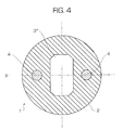
- Fig. 4 shows an optical fiber cable with a polygonal cavity according to a fourth embodiment.
- Fig. 5 is a cross-sectional view of an optical fiber cable showing increased fiber excess length capacity.
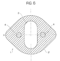
- Fig. 6 shows an optical fiber with a non-circular cavity and exterior according to a fifth embodiment.
- FIG. 1 A first embodiment of the present invention is shown in Fig. 1.
- the fiber optic cable 1 has a circular outer periphery 2 and a non-circular cavity 3.
- One or more optical fibers (not shown) are inserted in the cavity 3.
- Strength members 4, 4 extend longitudinally within the cable 1 in the same direction as the cavity 3.
- a minor axis X of the cavity 3 in cross-section is substantially aligned with a line connecting the strength members 4, 4.
- the cable has a lower crush resistance in a direction parallel to the minor axis of the cavity, and therefore the minor axis is aligned with a line joining the strength members.
- the minor axis does not have to exactly coincide with or be exactly parallel to the line joining the strength members, i.e., there can be an offset in either direction and/or an angle therebetween.
- the term "substantially aligned" is intended to encompass such an offset and/or angle. The same is true with respect to the major axis and a line perpendicular to the line joining the strength members.
- the added crush resistance offered by using an elongated cavity with the major axis perpendicular to the plane containing the strength members will not be affected significantly by vertical, horizontal and/or angular offsets of the cavity with respect to the plane containing the strength members and/or the plane perpendicular thereto.
- the amount of translational offset in any direction is preferably equal to or less than half the dimension of the minor axis of the cavity.
- Angular offsets are preferably equal to or less than 15 degrees.
- the invention is not intended to be limited to these preferred ranges.
- the cable of the present invention has improved crush resistance in a plane normal to a plane containing the strength members and also affords an additional thermal window for the contained optical fibers to buckle during thermal cycling.
- the non-circular cavity reduces crush resistance in the direction along the minor axis of the cavity.
- the strengthening members are intended to compensate at least somewhat for this reduced crush resistance.
- the non-circular cavity imposes a preferential crush resistance rather than a balanced crush resistance.
- a circular exterior with a non-circular cavity oriented such that the major axis coincides with the crush loading direction will endure higher crush loads than the same size circular section unit with a circular cavity whose diameter is the same as the minor axis of the elliptical cavity.
- the polygonal cavity is preferably, though not necessarily, oriented such that a vertical side lies along the crush load direction at the lateral extremities of the cavity.
- the cavity 3 in Fig. 1 has straight vertical sides and rounded or curved ends, i.e., it has a "race-track" shape. It is desirable to make the radius of curvature of the ends of the cavity as large as possible, and therefore the ends are preferably semicircular.
- the cable jacket might be made of polyethylene (high, medium or low density), halogen free flame retardant material, polypropylene, polyvinylchloride (PVC), and/or polyamide (PA).
- the strength member might be made of glass fiber reinforced plastic, steel, and/or aramid reinforced plastic.
- the filling compound might be a silicon based water blocking gel or polyolefin based gel.
- the above materials are only examples, and the present invention is not intended to be limited to these materials.
- the cavity can have different shapes, as shown in the other preferred embodiments in Figs. 2-4, provided that the minor axis is substantially aligned with the line connecting the strength members.
- the same reference numbers in Figs. 1-4 are used to designate the same elements.
- the cavity 3' has an elliptical shape.
- additional mechanisms act to improve the crush performance in the direction along the major axis of the ellipse.
- the first mechanism has to do with the curvature of the lateral extremity of the cavity.
- the elliptical cavity will have a smaller radius of curvature than a circular one causing a lower stress concentration, slower evolution of plastic strain and a subsequently higher collapse load.
- the second has to do with the buckling stability of the cavity and also depends on this curvature.
- the elliptical cavity is less curved at the lateral extremity and therefore has a higher local buckling stability.
- the cavity 3" has a rectangular shape.
- the sharp corners of the rectangular shaped cavity can be rounded (not shown in the drawing figures), i.e., they can be made to have a radius of curvature.
- the cavity 3"' has a polygonal shape.
- the variation in cavity shape can be continuously characterized by three geometric parameters; the aspect ratio a/b where a is the cavity width and b is the cavity height, and the conic factor p which characterizes the nature of the roundness of the corners of the cavity. See Fig. 2, for example.
- the conic factor is used to characterize the nature of the curvature of the comers in the elliptical cavities and rectangular shaped cavities with rounded corners. If the value of conic factor is 0.414, then the corners will be rounded with a circular shaped corner. If the value is greater than 0.414, then the comers will become sharper and the shape will be more like a rectangle with sharp corners. If the value is less than 0.414, the corners are smoothed into an elliptical shape.
- the geometry can be characterized by the number of sides of the polygon (N), the aspect ratio of the polygon, and the radius of the vertices if rounded.
- Fig. 5 is a cross-sectional view of an optical fiber cable showing increased fiber excess length capacity for an elongated cavity 3 (same as Fig. 1) as compared to a circular cavity C.
- the dashes show the path of the optical fibers within the cavities.
- a cable cross-section with a circular perimeter and non-circular cavity e.g., race-track, rectangular or polygonal shaped cavity
- an aspect ratio (a/b) less than 1 will also provide more excess length capacity.
- the excess length of fiber in a circular cavity is assumed to be generated via the fiber (or fiber bundle) buckling from a straight axial path coinciding with the cable axis, into a helical path whose axis coincides with the cable axis and that has a helical radius equal to the radius of the circular cavity.
- the fiber With an elongated cavity 3 having a minor axis equal to the diameter of the aforementioned circular cavity C, the fiber will buckle into an elongated helix allowing for more excess length of fiber.
- the strength member size can be reduced due to less stiffness requirement for the cable. With a smaller strength member, less plastic will be required to sufficiently encapsulate the strength member and will yield a lower coefficient of thermal expansion which in turn allows for more excess fiber length in the cable while maintaining cold temperature performance.
- the cables described above can be modified to include such a feature.
- the cables described above can be modified to include such a feature.
- the cable 1 shown in Fig. 6. The crush resistance of the cable with the non-circular cavity is improved in the direction perpendicular to the plane of the strength members, but is somewhat reduced in the direction parallel to the plane.
- the exterior shape of the cable is such that its major axis is parallel to the plane containing the strength members and with the minor axis of the cavity also being aligned with the plane containing the strength members, the crush resistance is improved in all directions.
- the invention is not intended to be limited to cavities in which the minor and/or major axes exactly coincide with or are parallel to the line joining the strength members, i.e., there can be an offset in either direction and/or an angle therebetween.
Landscapes
- Physics & Mathematics (AREA)
- General Physics & Mathematics (AREA)
- Optics & Photonics (AREA)
- Light Guides In General And Applications Therefor (AREA)
- Insulated Conductors (AREA)
- Cable Accessories (AREA)
- Waveguide Aerials (AREA)
- Extrusion Moulding Of Plastics Or The Like (AREA)
Abstract
Description
Claims (13)
- An optical fiber cable (1) comprising:a cable jacket having a longitudinally extending inner cavity (3) with a non-circular cross section; andat least two longitudinally extending strength members (4) in the cable jacket, wherein the non-circular cross section is disposed so that a minor axis thereof is substantially aligned with a line joining said at least two longitudinally extending strength members.
- The optical fiber cable recited in claim 1, wherein the minor axis is parallel with the line joining said at least two longitudinally extending strength members (4).
- The optical fiber recited in claim 1, wherein the minor axis is coincident with the line joining said at least two longitudinally extending strength members.
- The optical fiber recited in claim 1, wherein an offset of the minor axis from the line joining said strength members is equal or less than one-half the dimension of the minor axis of the cavity.
- The optical fiber recited in claim 1, wherein an angular offset between the minor axis and the line joining said strength member is equal or less than 15 degrees.
- The optical fiber cable recited in one of claims 1 to 5, wherein the non-circular cross section (3) has a shape that is in the form of a rectangle with a semi-circle disposed at each longitudinal end thereof.
- The optical fiber cable recited in one of claims 1 to 6, wherein a major axis of the non-circular shape (3) is substantially perpendicular to the line joining said at least two strength members.
- The optical fiber cable recited in one of claims 1 to 5 and 7, wherein the cavity (3) has a polygonal shape.
- The optical fiber cable recited in one of claims 1 to 5 and 7, wherein the cavity is rectangular.
- The optical fiber cable recited in one of claims 1 to 9, wherein an outer periphery (2) of said cable jacket has a circular cross section.
- The optical fiber cable recited in one of claims 1 to 9, wherein an outer periphery (2) of said cable jacket has a non-circular cross section.
- The optical fiber cable recited in claim 11, wherein a major axis of the non-circular cross section of the outer periphery (2) of said cable jacket is substantially aligned with the line joining said at least two longitudinally extending strength members (4).
- An optical fiber cable (1) comprising:wherein, at any given station along said fiber optic cable, the noncircular cross section is arranged such that a minor axis thereof coincides with a line joining center points of said at least two longitudinally extending strength members at that given station.at least two longitudinally extending strength members (4); anda cable jacket having an outer periphery (2) with a circular cross section and a longitudinally extending inner cavity (3) with a non-circular cross section, the non-circular cross section having a shape that is in the form of a rectangle with a semi-circle disposed at each longitudinal end thereof,
Applications Claiming Priority (2)
| Application Number | Priority Date | Filing Date | Title |
|---|---|---|---|
| US09/335,911 US6314224B1 (en) | 1999-06-18 | 1999-06-18 | Thick-walled cable jacket with non-circular cavity cross section |
| US335911 | 1999-06-18 |
Publications (2)
| Publication Number | Publication Date |
|---|---|
| EP1061394A1 true EP1061394A1 (en) | 2000-12-20 |
| EP1061394B1 EP1061394B1 (en) | 2009-11-25 |
Family
ID=23313749
Family Applications (1)
| Application Number | Title | Priority Date | Filing Date |
|---|---|---|---|
| EP00401236A Expired - Lifetime EP1061394B1 (en) | 1999-06-18 | 2000-05-05 | Thick-walled cable jacket with non-circular cavity cross section |
Country Status (7)
| Country | Link |
|---|---|
| US (1) | US6314224B1 (en) |
| EP (1) | EP1061394B1 (en) |
| JP (1) | JP4503785B2 (en) |
| CN (1) | CN1209651C (en) |
| AT (1) | ATE449977T1 (en) |
| BR (1) | BR0002571A (en) |
| DE (1) | DE60043372D1 (en) |
Cited By (4)
| Publication number | Priority date | Publication date | Assignee | Title |
|---|---|---|---|---|
| WO2012170391A1 (en) * | 2011-06-10 | 2012-12-13 | Corning Cable Systems Llc | Fiber optic cables allowing fiber translation to reduce bend attenuation |
| AU2015258303B2 (en) * | 2011-06-10 | 2017-06-08 | Corning Optical Communications LLC | Fiber optic cables allowing fiber translation to reduce bend attenuation |
| EP3115816A4 (en) * | 2014-03-06 | 2017-10-04 | Fujikura Ltd. | Optical cable |
| EP4625017A1 (en) * | 2024-03-28 | 2025-10-01 | Prysmian S.p.A. | Easy-access flat drop cable |
Families Citing this family (106)
| Publication number | Priority date | Publication date | Assignee | Title |
|---|---|---|---|---|
| FR2810747B1 (en) * | 2000-06-23 | 2002-12-20 | Acome Soc Coop Travailleurs | OPTICAL CABLE WITH CONTINUOUS ACCESSIBILITY |
| ATE399998T1 (en) * | 2001-03-14 | 2008-07-15 | Chiral Photonics Inc | CHIRAL FIBER BRAGG GRID |
| US20030032146A1 (en) * | 2001-07-10 | 2003-02-13 | Dwulet Francis Edward | Enzyme/tag binding and detection system |
| JP3768901B2 (en) * | 2002-02-28 | 2006-04-19 | 松下電器産業株式会社 | Manufacturing method of three-dimensional optical waveguide |
| US7277615B2 (en) * | 2002-12-19 | 2007-10-02 | Corning Cable Systems, Llc. | Fiber optic cable having a dry insert and methods of making the same |
| US6970629B2 (en) * | 2002-12-19 | 2005-11-29 | Corning Cable Systems Llc | Optical tube assembly having a dry insert and methods of making the same |
| US7415181B2 (en) * | 2005-07-29 | 2008-08-19 | Corning Cable Systems Llc | Fiber optic cables and assemblies for fiber to the subscriber applications |
| US7254302B2 (en) * | 2002-12-19 | 2007-08-07 | Corning Cable Systems, Llc. | Optical tube assembly having a dry insert and methods of making the same |
| US7471862B2 (en) * | 2002-12-19 | 2008-12-30 | Corning Cable Systems, Llc | Dry fiber optic cables and assemblies |
| US20090190890A1 (en) * | 2002-12-19 | 2009-07-30 | Freeland Riley S | Fiber optic cable having a dry insert and methods of making the same |
| US7336873B2 (en) | 2002-12-19 | 2008-02-26 | Corning Cable Systems, Llc. | Optical tube assembly having a dry insert and methods of making the same |
| US7406232B2 (en) * | 2006-08-31 | 2008-07-29 | Corning Cable Systems Llc | Non-round fiber optic cable having improved major axis crush resistance |
| US20090034918A1 (en) * | 2007-07-31 | 2009-02-05 | William Eric Caldwell | Fiber optic cables having coupling and methods therefor |
| DK2206001T3 (en) * | 2007-11-09 | 2014-07-07 | Draka Comteq Bv | Optical fiber resistant to microbending |
| US8081853B2 (en) * | 2007-11-09 | 2011-12-20 | Draka Comteq, B.V. | Single-fiber drop cables for MDU deployments |
| US8145026B2 (en) * | 2007-11-09 | 2012-03-27 | Draka Comteq, B.V. | Reduced-size flat drop cable |
| US8031997B2 (en) * | 2007-11-09 | 2011-10-04 | Draka Comteq, B.V. | Reduced-diameter, easy-access loose tube cable |
| US8467650B2 (en) * | 2007-11-09 | 2013-06-18 | Draka Comteq, B.V. | High-fiber-density optical-fiber cable |
| US8600206B2 (en) * | 2008-11-07 | 2013-12-03 | Draka Comteq, B.V. | Reduced-diameter optical fiber |
| US8041168B2 (en) * | 2007-11-09 | 2011-10-18 | Draka Comteq, B.V. | Reduced-diameter ribbon cables with high-performance optical fiber |
| US8165439B2 (en) * | 2007-11-09 | 2012-04-24 | Draka Comteq, B.V. | ADSS cables with high-performance optical fiber |
| US8041167B2 (en) | 2007-11-09 | 2011-10-18 | Draka Comteq, B.V. | Optical-fiber loose tube cables |
| FR2929716B1 (en) * | 2008-04-04 | 2011-09-16 | Draka Comteq France Sa | OPTICAL FIBER WITH DISPERSION OFFSET. |
| FR2930997B1 (en) | 2008-05-06 | 2010-08-13 | Draka Comteq France Sa | OPTICAL FIBER MONOMODE |
| FR2931253B1 (en) * | 2008-05-16 | 2010-08-20 | Draka Comteq France Sa | FIBER OPTIC TELECOMMUNICATION CABLE |
| FR2932932B1 (en) * | 2008-06-23 | 2010-08-13 | Draka Comteq France Sa | MULTIPLEX WAVE LENGTH OPTIC SYSTEM WITH MULTIMODE OPTIC FIBERS |
| FR2933779B1 (en) * | 2008-07-08 | 2010-08-27 | Draka Comteq France | MULTIMODE OPTIC FIBERS |
| US7970247B2 (en) * | 2008-09-12 | 2011-06-28 | Draka Comteq B.V. | Buffer tubes for mid-span storage |
| US20100109174A1 (en) | 2008-11-05 | 2010-05-06 | George Cornelius Abernathy | Method for drop cable having an oval cavity |
| FR2938389B1 (en) * | 2008-11-07 | 2011-04-15 | Draka Comteq France | MULTIMODE OPTICAL SYSTEM |
| DK2187486T3 (en) * | 2008-11-12 | 2014-07-07 | Draka Comteq Bv | Reinforcing optical fiber and method of manufacture |
| WO2010065632A1 (en) | 2008-12-02 | 2010-06-10 | Corning Cable Systems Llc | Optical fiber array cables and associated fiber optic cables and systems |
| FR2939246B1 (en) * | 2008-12-02 | 2010-12-24 | Draka Comteq France | AMPLIFIER OPTICAL FIBER AND METHOD OF MANUFACTURE |
| FR2939522B1 (en) * | 2008-12-08 | 2011-02-11 | Draka Comteq France | OPTICAL FIBER AMPLIFIER RESISTANT TO IONIZING RADIATION |
| FR2939911B1 (en) * | 2008-12-12 | 2011-04-08 | Draka Comteq France | SOLDERED OPTICAL FIBER, TELECOMMUNICATION CABLE COMPRISING MULTIPLE OPTICAL FIBERS AND METHOD FOR MANUFACTURING SUCH A FIBER |
| NL1036343C2 (en) * | 2008-12-19 | 2010-06-22 | Draka Comteq Bv | METHOD AND APPARATUS FOR MANUFACTURING AN OPTICAL FORM. |
| EP2204681B1 (en) | 2008-12-30 | 2016-03-09 | Draka Comteq B.V. | Optical fibre cable comprising a perforated water-blocking element |
| WO2010077132A1 (en) * | 2008-12-31 | 2010-07-08 | Draka Comteq B.V. | Uvled apparatus for curing glass-fiber coatings |
| FR2940839B1 (en) * | 2009-01-08 | 2012-09-14 | Draka Comteq France | INDEX GRADIENT MULTIMODAL OPTICAL FIBER, METHODS FOR CHARACTERIZATION AND MANUFACTURE OF SUCH A FIBER |
| FR2941539B1 (en) * | 2009-01-23 | 2011-02-25 | Draka Comteq France | OPTICAL FIBER MONOMODE |
| FR2941541B1 (en) * | 2009-01-27 | 2011-02-25 | Draka Comteq France | OPTICAL FIBER MONOMODE |
| FR2941540B1 (en) * | 2009-01-27 | 2011-05-06 | Draka Comteq France | MONOMODE OPTICAL FIBER HAVING ENHANCED EFFECTIVE SURFACE |
| US8489219B1 (en) | 2009-01-30 | 2013-07-16 | Draka Comteq B.V. | Process for making loose buffer tubes having controlled excess fiber length and reduced post-extrusion shrinkage |
| US9360647B2 (en) * | 2009-02-06 | 2016-06-07 | Draka Comteq, B.V. | Central-tube cable with high-conductivity conductors encapsulated with high-dielectric-strength insulation |
| FR2942571B1 (en) * | 2009-02-20 | 2011-02-25 | Draka Comteq France | AMPLIFIER OPTICAL FIBER COMPRISING NANOSTRUCTURES |
| FR2942551B1 (en) * | 2009-02-23 | 2011-07-15 | Draka Comteq France | CABLE COMPRISING ELEMENTS TO BE EXTRACTED, METHOD OF EXTRACTING THESE ELEMENTS AND METHOD OF MANUFACTURING THE SAME |
| US8625945B1 (en) | 2009-05-13 | 2014-01-07 | Draka Comteq, B.V. | Low-shrink reduced-diameter dry buffer tubes |
| US8625944B1 (en) | 2009-05-13 | 2014-01-07 | Draka Comteq, B.V. | Low-shrink reduced-diameter buffer tubes |
| FR2946436B1 (en) * | 2009-06-05 | 2011-12-09 | Draka Comteq France | MULTIMODE OPTICAL FIBER WITH LARGE BANDWIDTH WITH AN OPTIMIZED HEAT-SLEEVE INTERFACE |
| US20110026889A1 (en) * | 2009-07-31 | 2011-02-03 | Draka Comteq B.V. | Tight-Buffered Optical Fiber Unit Having Improved Accessibility |
| FR2953605B1 (en) * | 2009-12-03 | 2011-12-16 | Draka Comteq France | MULTIMODE OPTICAL FIBER WITH BROAD BANDWIDTH AND LOW BENDBACK LOSSES |
| FR2953030B1 (en) * | 2009-11-25 | 2011-11-18 | Draka Comteq France | MULTIMODE OPTICAL FIBER WITH LARGE BANDWIDTH WITH AN OPTIMIZED HEAT-SLEEVE INTERFACE |
| FR2957153B1 (en) * | 2010-03-02 | 2012-08-10 | Draka Comteq France | MULTIMODE OPTICAL FIBER WITH BROAD BANDWIDTH AND LOW BENDBACK LOSSES |
| US9014525B2 (en) | 2009-09-09 | 2015-04-21 | Draka Comteq, B.V. | Trench-assisted multimode optical fiber |
| FR2949870B1 (en) * | 2009-09-09 | 2011-12-16 | Draka Compteq France | MULTIMODE OPTICAL FIBER HAVING IMPROVED BENDING LOSSES |
| FR2953029B1 (en) * | 2009-11-25 | 2011-11-18 | Draka Comteq France | MULTIMODE OPTICAL FIBER WITH LARGE BANDWIDTH WITH AN OPTIMIZED HEAT-SLEEVE INTERFACE |
| FR2953606B1 (en) * | 2009-12-03 | 2012-04-27 | Draka Comteq France | MULTIMODE OPTICAL FIBER WITH BROAD BANDWIDTH AND LOW BENDBACK LOSSES |
| US8306380B2 (en) * | 2009-09-14 | 2012-11-06 | Draka Comteq, B.V. | Methods and devices for cable insertion into latched-duct conduit |
| FR2950156B1 (en) * | 2009-09-17 | 2011-11-18 | Draka Comteq France | MULTIMODE OPTIC FIBER |
| FR2950443B1 (en) * | 2009-09-22 | 2011-11-18 | Draka Comteq France | OPTICAL FIBER FOR SUM FREQUENCY GENERATION AND METHOD FOR MANUFACTURING THE SAME |
| US8805143B2 (en) * | 2009-10-19 | 2014-08-12 | Draka Comteq, B.V. | Optical-fiber cable having high fiber count and high fiber density |
| FR2952634B1 (en) * | 2009-11-13 | 2011-12-16 | Draka Comteq France | RARE EARTH DOPED SILICA FIBER WITH LOW DIGITAL OPENING |
| US9042693B2 (en) * | 2010-01-20 | 2015-05-26 | Draka Comteq, B.V. | Water-soluble water-blocking element |
| EP3399357B1 (en) * | 2010-02-01 | 2024-12-11 | Draka Comteq B.V. | Non-zero dispersion shifted optical fiber having a short cutoff wavelength |
| DK2352047T3 (en) * | 2010-02-01 | 2019-11-11 | Draka Comteq Bv | Non-zero dispersion-switched optical fiber with a large effective area |
| EP2369379B1 (en) * | 2010-03-17 | 2015-05-06 | Draka Comteq B.V. | Fibre optique monomode ayant des pertes par courbures réduites |
| US8885999B2 (en) * | 2010-03-19 | 2014-11-11 | Corning Cable Systems Llc | Optical USB cable with controlled fiber positioning |
| US8693830B2 (en) | 2010-04-28 | 2014-04-08 | Draka Comteq, B.V. | Data-center cable |
| PT2390700T (en) | 2010-05-03 | 2016-10-19 | Draka Comteq Bv | PACKAGED OPTICAL FIBER CABLES |
| DK2388239T3 (en) | 2010-05-20 | 2017-04-24 | Draka Comteq Bv | Curing apparatus using angled UV LEDs |
| US8625947B1 (en) | 2010-05-28 | 2014-01-07 | Draka Comteq, B.V. | Low-smoke and flame-retardant fiber optic cables |
| US8871311B2 (en) | 2010-06-03 | 2014-10-28 | Draka Comteq, B.V. | Curing method employing UV sources that emit differing ranges of UV radiation |
| FR2962230B1 (en) | 2010-07-02 | 2012-07-27 | Draka Comteq France | OPTICAL FIBER MONOMODE |
| US8682123B2 (en) | 2010-07-15 | 2014-03-25 | Draka Comteq, B.V. | Adhesively coupled optical fibers and enclosing tape |
| EP2418183B1 (en) | 2010-08-10 | 2018-07-25 | Draka Comteq B.V. | Method for curing coated glass fibres providing increased UVLED intensitiy |
| US8571369B2 (en) | 2010-09-03 | 2013-10-29 | Draka Comteq B.V. | Optical-fiber module having improved accessibility |
| FR2966256B1 (en) | 2010-10-18 | 2012-11-16 | Draka Comteq France | MULTIMODE OPTICAL FIBER INSENSITIVE TO LOSSES BY |
| US8824845B1 (en) | 2010-12-03 | 2014-09-02 | Draka Comteq, B.V. | Buffer tubes having reduced stress whitening |
| DK2482106T5 (en) | 2011-01-31 | 2014-09-22 | Draka Comteq Bv | Multi-mode fiber |
| FR2971061B1 (en) | 2011-01-31 | 2013-02-08 | Draka Comteq France | BROAD BANDWIDTH OPTICAL FIBER WITH LOW CURB LOSSES |
| PT2678728T (en) | 2011-02-21 | 2018-07-05 | Draka Comteq Bv | Fiber Optic Interconnect Cable |
| EP2495589A1 (en) | 2011-03-04 | 2012-09-05 | Draka Comteq B.V. | Rare earth doped amplifying optical fiber for compact devices and method of manufacturing thereof |
| EP2503368A1 (en) | 2011-03-24 | 2012-09-26 | Draka Comteq B.V. | Multimode optical fiber with improved bend resistance |
| EP2506044A1 (en) | 2011-03-29 | 2012-10-03 | Draka Comteq B.V. | Multimode optical fiber |
| EP2518546B1 (en) | 2011-04-27 | 2018-06-20 | Draka Comteq B.V. | High-bandwidth, radiation-resistant multimode optical fiber |
| ES2438173T3 (en) | 2011-05-27 | 2014-01-16 | Draka Comteq Bv | Single mode fiber optic |
| EP2533082B1 (en) | 2011-06-09 | 2013-12-25 | Draka Comteq BV | Single mode optical fiber |
| WO2013003621A2 (en) * | 2011-06-30 | 2013-01-03 | Saint-Gobain Ceramics & Plastics, Inc. | Optical fiber having scintillation quencher, a radiation sensor and a radiation detection apparatus including the optical fiber and a method of making and using the same |
| DK2541292T3 (en) | 2011-07-01 | 2014-12-01 | Draka Comteq Bv | A multimode optical fiber |
| EP2584340A1 (en) | 2011-10-20 | 2013-04-24 | Draka Comteq BV | Hydrogen sensing fiber and hydrogen sensor |
| NL2007831C2 (en) | 2011-11-21 | 2013-05-23 | Draka Comteq Bv | Apparatus and method for carrying out a pcvd deposition process. |
| US8676012B2 (en) | 2012-01-20 | 2014-03-18 | Corning Cable Systems Llc | Fiber optic cable for very-short-distance networks |
| US8929701B2 (en) | 2012-02-15 | 2015-01-06 | Draka Comteq, B.V. | Loose-tube optical-fiber cable |
| WO2013160714A1 (en) | 2012-04-27 | 2013-10-31 | Draka Comteq Bv | Hybrid single and multimode optical fiber for a home network |
| US9170389B2 (en) | 2012-08-28 | 2015-10-27 | Corning Cable Systems Llc | Hybrid fiber optic cable systems |
| US9188754B1 (en) | 2013-03-15 | 2015-11-17 | Draka Comteq, B.V. | Method for manufacturing an optical-fiber buffer tube |
| WO2015144397A1 (en) * | 2014-03-25 | 2015-10-01 | Tyco Electronics Raychem Bvba | Cable fixation and sealing system |
| CN104181656B (en) * | 2014-08-29 | 2016-03-16 | 长飞光纤光缆股份有限公司 | A kind of dry type all dielectric optical fibre band optical cable and preparation method thereof |
| JP6163227B1 (en) * | 2016-04-21 | 2017-07-12 | 株式会社フジクラ | Splitting method of optical cable |
| CN106646796A (en) * | 2016-11-24 | 2017-05-10 | 北京亨通斯博通讯科技有限公司 | Triangular cross section drop optical cable and manufacturing method thereof |
| CN107065091B (en) * | 2017-02-28 | 2019-06-07 | 烽火通信科技股份有限公司 | A kind of optical cable and its manufacturing method of easily putting in a skylight |
| DE102017213070A1 (en) * | 2017-07-28 | 2019-01-31 | Fraunhofer-Gesellschaft zur Förderung der angewandten Forschung e.V. | Method of fabricating a MEMS mirror assembly and MEMS mirror assembly |
| EP3911981B1 (en) * | 2019-01-19 | 2026-02-18 | Corning Research & Development Corporation | Unitized fiber optic cables |
| CN113703107B (en) * | 2021-07-27 | 2023-05-09 | 杭州富通通信技术股份有限公司 | ribbon cable |
| EP4416542A1 (en) * | 2021-10-11 | 2024-08-21 | PPC Broadband Fiber Ltd. | Optical fiber cable that provides enhanced sealing and selectively tears so as to provide enhanced access to an optical fiber |
| CN115840274B (en) * | 2023-01-09 | 2023-09-22 | 江苏中天科技股份有限公司 | A ribbon optical cable |
Citations (5)
| Publication number | Priority date | Publication date | Assignee | Title |
|---|---|---|---|---|
| US4038489A (en) * | 1974-05-31 | 1977-07-26 | The Post Office | Cables |
| FR2555764A1 (en) * | 1983-11-24 | 1985-05-31 | Nonclerq Bernard | Cable for transmission by optical fibre and method for making connections using it |
| JPH0320704A (en) * | 1989-03-31 | 1991-01-29 | Ube Nitto Kasei Co Ltd | Optical fiber cord |
| EP0676654A2 (en) * | 1994-04-07 | 1995-10-11 | Pirelli Cable Corporation | Optical fiber core and cable with reinforced buffer tube loosely enclosing optical fibers |
| US5651081A (en) * | 1994-06-10 | 1997-07-22 | Commscope, Inc. | Composite fiber optic and electrical cable and associated fabrication method |
Family Cites Families (16)
| Publication number | Priority date | Publication date | Assignee | Title |
|---|---|---|---|---|
| US676654A (en) * | 1901-02-14 | 1901-06-18 | Gamelise Nourie | Headed-grain stacker. |
| GB1422147A (en) | 1972-06-06 | 1976-01-21 | Bicc Ltd | Optical guides |
| GB1480206A (en) | 1976-05-28 | 1977-07-20 | Bicc Ltd | Optical guides |
| GB1486764A (en) | 1976-07-27 | 1977-09-21 | Standard Telephones Cables Ltd | Cable |
| GB1561806A (en) | 1976-09-22 | 1980-03-05 | Post Office | Dielectric optical waveguide cables |
| US4199225A (en) | 1978-04-07 | 1980-04-22 | Bicc Limited | Optical guides |
| US4420220A (en) | 1979-06-25 | 1983-12-13 | Bicc Public Limited Company | Optical guides |
| JPS6086515A (en) | 1983-10-18 | 1985-05-16 | Junkosha Co Ltd | Light transmitting linear body and flat cable using it |
| US5067831A (en) | 1989-12-13 | 1991-11-26 | Lumenyte International Corporation | Linear optical conduits |
| US5155304A (en) | 1990-07-25 | 1992-10-13 | At&T Bell Laboratories | Aerial service wire |
| DE4141054C1 (en) | 1991-12-13 | 1993-07-22 | Deutsche Aerospace Ag, 8000 Muenchen, De | |
| US5222180A (en) | 1992-10-29 | 1993-06-22 | Hoechst Celanese Corp. | Polymer optical fibre bundle and method of making same |
| US5333229A (en) | 1993-03-31 | 1994-07-26 | W. L. Gore & Associates, Inc. | Asymmetrical polarization-maintaining optical waveguide and process for manufacture thereof |
| US5448670A (en) | 1994-06-10 | 1995-09-05 | Commscope, Inc. | Elliptical aerial self-supporting fiber optic cable and associated apparatus and methods |
| US5675686A (en) | 1995-07-05 | 1997-10-07 | W. L. Gore & Associates, Inc. | Buffer material for optical signal transmission media |
| JPH09152529A (en) * | 1995-11-29 | 1997-06-10 | Mitsubishi Cable Ind Ltd | Optical fiber cable |
-
1999
- 1999-06-18 US US09/335,911 patent/US6314224B1/en not_active Expired - Lifetime
-
2000
- 2000-05-05 EP EP00401236A patent/EP1061394B1/en not_active Expired - Lifetime
- 2000-05-05 DE DE60043372T patent/DE60043372D1/en not_active Expired - Lifetime
- 2000-05-05 AT AT00401236T patent/ATE449977T1/en not_active IP Right Cessation
- 2000-06-01 JP JP2000163915A patent/JP4503785B2/en not_active Expired - Fee Related
- 2000-06-09 CN CNB001181335A patent/CN1209651C/en not_active Expired - Fee Related
- 2000-06-12 BR BR0002571-2A patent/BR0002571A/en not_active Application Discontinuation
Patent Citations (5)
| Publication number | Priority date | Publication date | Assignee | Title |
|---|---|---|---|---|
| US4038489A (en) * | 1974-05-31 | 1977-07-26 | The Post Office | Cables |
| FR2555764A1 (en) * | 1983-11-24 | 1985-05-31 | Nonclerq Bernard | Cable for transmission by optical fibre and method for making connections using it |
| JPH0320704A (en) * | 1989-03-31 | 1991-01-29 | Ube Nitto Kasei Co Ltd | Optical fiber cord |
| EP0676654A2 (en) * | 1994-04-07 | 1995-10-11 | Pirelli Cable Corporation | Optical fiber core and cable with reinforced buffer tube loosely enclosing optical fibers |
| US5651081A (en) * | 1994-06-10 | 1997-07-22 | Commscope, Inc. | Composite fiber optic and electrical cable and associated fabrication method |
Non-Patent Citations (1)
| Title |
|---|
| PATENT ABSTRACTS OF JAPAN vol. 015, no. 144 (P - 1189) 11 April 1991 (1991-04-11) * |
Cited By (6)
| Publication number | Priority date | Publication date | Assignee | Title |
|---|---|---|---|---|
| WO2012170391A1 (en) * | 2011-06-10 | 2012-12-13 | Corning Cable Systems Llc | Fiber optic cables allowing fiber translation to reduce bend attenuation |
| AU2015258303B2 (en) * | 2011-06-10 | 2017-06-08 | Corning Optical Communications LLC | Fiber optic cables allowing fiber translation to reduce bend attenuation |
| AU2015258303C1 (en) * | 2011-06-10 | 2017-10-05 | Corning Optical Communications LLC | Fiber optic cables allowing fiber translation to reduce bend attenuation |
| EP3115816A4 (en) * | 2014-03-06 | 2017-10-04 | Fujikura Ltd. | Optical cable |
| US10061096B2 (en) | 2014-03-06 | 2018-08-28 | Fujikura Ltd. | Optical cable |
| EP4625017A1 (en) * | 2024-03-28 | 2025-10-01 | Prysmian S.p.A. | Easy-access flat drop cable |
Also Published As
| Publication number | Publication date |
|---|---|
| ATE449977T1 (en) | 2009-12-15 |
| EP1061394B1 (en) | 2009-11-25 |
| CN1278071A (en) | 2000-12-27 |
| BR0002571A (en) | 2001-01-02 |
| DE60043372D1 (en) | 2010-01-07 |
| JP4503785B2 (en) | 2010-07-14 |
| JP2001021780A (en) | 2001-01-26 |
| CN1209651C (en) | 2005-07-06 |
| US6314224B1 (en) | 2001-11-06 |
Similar Documents
| Publication | Publication Date | Title |
|---|---|---|
| EP1061394B1 (en) | Thick-walled cable jacket with non-circular cavity cross section | |
| US5212756A (en) | Fiber optic ribbon cable including flexible web | |
| CN1020961C (en) | Optical cable | |
| EP1887396B1 (en) | Optical fibre telecommunication cable | |
| EP0240165B1 (en) | Optical fiber cable | |
| US8238706B2 (en) | Flat drop cable with medial bump | |
| US4810834A (en) | Tensionproof cable | |
| US11079538B2 (en) | Foveal image inverter | |
| CN105934695A (en) | Optical cable | |
| US9581777B2 (en) | Coupling system for fiber optic cable using folded tape | |
| US6658187B2 (en) | Optical fiber cable assembly with interstitial support members | |
| US20030068146A1 (en) | Central strength member with reduced radial stiffness | |
| US7359600B2 (en) | Loose tube optical cable having straight aggregation structure | |
| US6067394A (en) | Structures of optical fiber cables self-reinforced against compression | |
| US20230258895A1 (en) | Sz strand retention of assymetrical optical fiber ribbon units by a conforming tensioned elastomer shell | |
| JP2000310729A (en) | Fiber optic cable with profiled fiber optic group | |
| EP4152067A1 (en) | Optical fiber cable | |
| US4695128A (en) | Fiber optic cable | |
| CN116224516A (en) | fiber optic cable | |
| CN1205442A (en) | Bushings for Optical Cables and Optical Cables | |
| US5420955A (en) | Optical cables having U-shaped carriers exhibiting enhanced crush performance | |
| US20080056650A1 (en) | Non-round fiber optic cable having improved major axis crush resistance | |
| WO2022004498A1 (en) | Optical fiber unit and optical fiber unit manufacturing method | |
| AU2018250693B2 (en) | Flat drop cable with features for enhanced stripability | |
| EP4095577A1 (en) | Optical cable with high aspect ratio strength rods |
Legal Events
| Date | Code | Title | Description |
|---|---|---|---|
| PUAI | Public reference made under article 153(3) epc to a published international application that has entered the european phase |
Free format text: ORIGINAL CODE: 0009012 |
|
| AK | Designated contracting states |
Kind code of ref document: A1 Designated state(s): AT BE CH CY DE DK ES FI FR GB GR IE IT LI LU MC NL PT SE |
|
| AX | Request for extension of the european patent |
Free format text: AL;LT;LV;MK;RO;SI |
|
| RIN1 | Information on inventor provided before grant (corrected) |
Inventor name: STEVENS, JOHN BOYET Inventor name: BARKER, JEFFREY S. Inventor name: BUCKLAND, ERIC Inventor name: ELISSON, PETER |
|
| 17P | Request for examination filed |
Effective date: 20010324 |
|
| 17Q | First examination report despatched |
Effective date: 20010530 |
|
| AKX | Designation fees paid |
Free format text: AT BE CH CY DE DK ES FI FR GB GR IE IT LI LU MC NL PT SE |
|
| RAP1 | Party data changed (applicant data changed or rights of an application transferred) |
Owner name: DRAKA COMTEQ B.V. |
|
| 17Q | First examination report despatched |
Effective date: 20010530 |
|
| RAP1 | Party data changed (applicant data changed or rights of an application transferred) |
Owner name: DRAKA COMTEQ B.V. |
|
| RAP1 | Party data changed (applicant data changed or rights of an application transferred) |
Owner name: DRAKA COMTEQ B.V. |
|
| GRAP | Despatch of communication of intention to grant a patent |
Free format text: ORIGINAL CODE: EPIDOSNIGR1 |
|
| GRAS | Grant fee paid |
Free format text: ORIGINAL CODE: EPIDOSNIGR3 |
|
| GRAA | (expected) grant |
Free format text: ORIGINAL CODE: 0009210 |
|
| AK | Designated contracting states |
Kind code of ref document: B1 Designated state(s): AT BE CH CY DE DK ES FI FR GB GR IE IT LI LU MC NL PT SE |
|
| REG | Reference to a national code |
Ref country code: GB Ref legal event code: FG4D |
|
| REG | Reference to a national code |
Ref country code: CH Ref legal event code: EP |
|
| REG | Reference to a national code |
Ref country code: IE Ref legal event code: FG4D |
|
| REF | Corresponds to: |
Ref document number: 60043372 Country of ref document: DE Date of ref document: 20100107 Kind code of ref document: P |
|
| REG | Reference to a national code |
Ref country code: NL Ref legal event code: VDEP Effective date: 20091125 |
|
| PG25 | Lapsed in a contracting state [announced via postgrant information from national office to epo] |
Ref country code: SE Free format text: LAPSE BECAUSE OF FAILURE TO SUBMIT A TRANSLATION OF THE DESCRIPTION OR TO PAY THE FEE WITHIN THE PRESCRIBED TIME-LIMIT Effective date: 20091125 Ref country code: FI Free format text: LAPSE BECAUSE OF FAILURE TO SUBMIT A TRANSLATION OF THE DESCRIPTION OR TO PAY THE FEE WITHIN THE PRESCRIBED TIME-LIMIT Effective date: 20091125 Ref country code: PT Free format text: LAPSE BECAUSE OF FAILURE TO SUBMIT A TRANSLATION OF THE DESCRIPTION OR TO PAY THE FEE WITHIN THE PRESCRIBED TIME-LIMIT Effective date: 20100325 |
|
| PG25 | Lapsed in a contracting state [announced via postgrant information from national office to epo] |
Ref country code: CY Free format text: LAPSE BECAUSE OF FAILURE TO SUBMIT A TRANSLATION OF THE DESCRIPTION OR TO PAY THE FEE WITHIN THE PRESCRIBED TIME-LIMIT Effective date: 20091125 |
|
| PG25 | Lapsed in a contracting state [announced via postgrant information from national office to epo] |
Ref country code: AT Free format text: LAPSE BECAUSE OF FAILURE TO SUBMIT A TRANSLATION OF THE DESCRIPTION OR TO PAY THE FEE WITHIN THE PRESCRIBED TIME-LIMIT Effective date: 20091125 Ref country code: BE Free format text: LAPSE BECAUSE OF FAILURE TO SUBMIT A TRANSLATION OF THE DESCRIPTION OR TO PAY THE FEE WITHIN THE PRESCRIBED TIME-LIMIT Effective date: 20091125 |
|
| PG25 | Lapsed in a contracting state [announced via postgrant information from national office to epo] |
Ref country code: DK Free format text: LAPSE BECAUSE OF FAILURE TO SUBMIT A TRANSLATION OF THE DESCRIPTION OR TO PAY THE FEE WITHIN THE PRESCRIBED TIME-LIMIT Effective date: 20091125 Ref country code: ES Free format text: LAPSE BECAUSE OF FAILURE TO SUBMIT A TRANSLATION OF THE DESCRIPTION OR TO PAY THE FEE WITHIN THE PRESCRIBED TIME-LIMIT Effective date: 20100308 Ref country code: NL Free format text: LAPSE BECAUSE OF FAILURE TO SUBMIT A TRANSLATION OF THE DESCRIPTION OR TO PAY THE FEE WITHIN THE PRESCRIBED TIME-LIMIT Effective date: 20091125 |
|
| PLBE | No opposition filed within time limit |
Free format text: ORIGINAL CODE: 0009261 |
|
| STAA | Information on the status of an ep patent application or granted ep patent |
Free format text: STATUS: NO OPPOSITION FILED WITHIN TIME LIMIT |
|
| PG25 | Lapsed in a contracting state [announced via postgrant information from national office to epo] |
Ref country code: GR Free format text: LAPSE BECAUSE OF FAILURE TO SUBMIT A TRANSLATION OF THE DESCRIPTION OR TO PAY THE FEE WITHIN THE PRESCRIBED TIME-LIMIT Effective date: 20100226 |
|
| 26N | No opposition filed |
Effective date: 20100826 |
|
| PG25 | Lapsed in a contracting state [announced via postgrant information from national office to epo] |
Ref country code: MC Free format text: LAPSE BECAUSE OF NON-PAYMENT OF DUE FEES Effective date: 20100531 |
|
| REG | Reference to a national code |
Ref country code: CH Ref legal event code: PL |
|
| PG25 | Lapsed in a contracting state [announced via postgrant information from national office to epo] |
Ref country code: LI Free format text: LAPSE BECAUSE OF NON-PAYMENT OF DUE FEES Effective date: 20100531 Ref country code: CH Free format text: LAPSE BECAUSE OF NON-PAYMENT OF DUE FEES Effective date: 20100531 |
|
| PG25 | Lapsed in a contracting state [announced via postgrant information from national office to epo] |
Ref country code: IT Free format text: LAPSE BECAUSE OF FAILURE TO SUBMIT A TRANSLATION OF THE DESCRIPTION OR TO PAY THE FEE WITHIN THE PRESCRIBED TIME-LIMIT Effective date: 20091125 |
|
| PG25 | Lapsed in a contracting state [announced via postgrant information from national office to epo] |
Ref country code: IE Free format text: LAPSE BECAUSE OF NON-PAYMENT OF DUE FEES Effective date: 20100505 |
|
| PG25 | Lapsed in a contracting state [announced via postgrant information from national office to epo] |
Ref country code: LU Free format text: LAPSE BECAUSE OF NON-PAYMENT OF DUE FEES Effective date: 20100505 |
|
| REG | Reference to a national code |
Ref country code: FR Ref legal event code: PLFP Year of fee payment: 17 |
|
| REG | Reference to a national code |
Ref country code: FR Ref legal event code: PLFP Year of fee payment: 18 |
|
| REG | Reference to a national code |
Ref country code: FR Ref legal event code: PLFP Year of fee payment: 19 |
|
| PGFP | Annual fee paid to national office [announced via postgrant information from national office to epo] |
Ref country code: DE Payment date: 20190530 Year of fee payment: 20 |
|
| PGFP | Annual fee paid to national office [announced via postgrant information from national office to epo] |
Ref country code: FR Payment date: 20190527 Year of fee payment: 20 |
|
| PGFP | Annual fee paid to national office [announced via postgrant information from national office to epo] |
Ref country code: GB Payment date: 20190528 Year of fee payment: 20 |
|
| REG | Reference to a national code |
Ref country code: DE Ref legal event code: R071 Ref document number: 60043372 Country of ref document: DE |
|
| REG | Reference to a national code |
Ref country code: GB Ref legal event code: PE20 Expiry date: 20200504 |
|
| PG25 | Lapsed in a contracting state [announced via postgrant information from national office to epo] |
Ref country code: GB Free format text: LAPSE BECAUSE OF EXPIRATION OF PROTECTION Effective date: 20200504 |