EP1061302A1 - Cable retainer - Google Patents
Cable retainer Download PDFInfo
- Publication number
- EP1061302A1 EP1061302A1 EP00112702A EP00112702A EP1061302A1 EP 1061302 A1 EP1061302 A1 EP 1061302A1 EP 00112702 A EP00112702 A EP 00112702A EP 00112702 A EP00112702 A EP 00112702A EP 1061302 A1 EP1061302 A1 EP 1061302A1
- Authority
- EP
- European Patent Office
- Prior art keywords
- trough
- cable retainer
- cable
- retainer
- longitudinal axis
- Prior art date
- Legal status (The legal status is an assumption and is not a legal conclusion. Google has not performed a legal analysis and makes no representation as to the accuracy of the status listed.)
- Granted
Links
- 230000014759 maintenance of location Effects 0.000 claims abstract description 26
- 230000000295 complement effect Effects 0.000 claims description 5
- 238000000034 method Methods 0.000 claims description 4
- 239000000758 substrate Substances 0.000 description 5
- 238000009434 installation Methods 0.000 description 1
- 238000012986 modification Methods 0.000 description 1
- 230000004048 modification Effects 0.000 description 1
Images


Classifications
-
- H—ELECTRICITY
- H02—GENERATION; CONVERSION OR DISTRIBUTION OF ELECTRIC POWER
- H02G—INSTALLATION OF ELECTRIC CABLES OR LINES, OR OF COMBINED OPTICAL AND ELECTRIC CABLES OR LINES
- H02G3/00—Installations of electric cables or lines or protective tubing therefor in or on buildings, equivalent structures or vehicles
- H02G3/26—Installations of cables, lines, or separate protective tubing therefor directly on or in walls, ceilings, or floors
-
- F—MECHANICAL ENGINEERING; LIGHTING; HEATING; WEAPONS; BLASTING
- F16—ENGINEERING ELEMENTS AND UNITS; GENERAL MEASURES FOR PRODUCING AND MAINTAINING EFFECTIVE FUNCTIONING OF MACHINES OR INSTALLATIONS; THERMAL INSULATION IN GENERAL
- F16L—PIPES; JOINTS OR FITTINGS FOR PIPES; SUPPORTS FOR PIPES, CABLES OR PROTECTIVE TUBING; MEANS FOR THERMAL INSULATION IN GENERAL
- F16L3/00—Supports for pipes, cables or protective tubing, e.g. hangers, holders, clamps, cleats, clips, brackets
- F16L3/22—Supports for pipes, cables or protective tubing, e.g. hangers, holders, clamps, cleats, clips, brackets specially adapted for supporting a number of parallel pipes at intervals
- F16L3/222—Supports for pipes, cables or protective tubing, e.g. hangers, holders, clamps, cleats, clips, brackets specially adapted for supporting a number of parallel pipes at intervals having single supports directly connected together
-
- F—MECHANICAL ENGINEERING; LIGHTING; HEATING; WEAPONS; BLASTING
- F16—ENGINEERING ELEMENTS AND UNITS; GENERAL MEASURES FOR PRODUCING AND MAINTAINING EFFECTIVE FUNCTIONING OF MACHINES OR INSTALLATIONS; THERMAL INSULATION IN GENERAL
- F16L—PIPES; JOINTS OR FITTINGS FOR PIPES; SUPPORTS FOR PIPES, CABLES OR PROTECTIVE TUBING; MEANS FOR THERMAL INSULATION IN GENERAL
- F16L3/00—Supports for pipes, cables or protective tubing, e.g. hangers, holders, clamps, cleats, clips, brackets
- F16L3/22—Supports for pipes, cables or protective tubing, e.g. hangers, holders, clamps, cleats, clips, brackets specially adapted for supporting a number of parallel pipes at intervals
- F16L3/223—Supports for pipes, cables or protective tubing, e.g. hangers, holders, clamps, cleats, clips, brackets specially adapted for supporting a number of parallel pipes at intervals each support having one transverse base for supporting the pipes
-
- H—ELECTRICITY
- H02—GENERATION; CONVERSION OR DISTRIBUTION OF ELECTRIC POWER
- H02G—INSTALLATION OF ELECTRIC CABLES OR LINES, OR OF COMBINED OPTICAL AND ELECTRIC CABLES OR LINES
- H02G3/00—Installations of electric cables or lines or protective tubing therefor in or on buildings, equivalent structures or vehicles
- H02G3/30—Installations of cables or lines on walls, floors or ceilings
Definitions
- the present invention relates generally to cable retainer devices and more specifically to single and multiple, stackable cable retainer devices.
- a first aspect of the present invention regards a cable retainer that has a body with a trough formed therein that extends along a longitudinal axis and a retention post extension that is attached to and extends away from the body along a direction that is parallel to the longitudinal axis.
- a second aspect of the present invention regards a method of retaining a cable that includes providing a cable retainer that has a body with a trough formed therein that extends along a longitudinal axis and a retention post extension that is attached to and extends away from the body along a direction that is parallel to the longitudinal axis. The method further includes placing a cable within the trough and wrapping a cable tie around the cable and the retention post extension.
- a third aspect of the present invention regards a cable retainer that has a first body with a first trough formed therein that extends along a longitudinal axis and a first latch structure.
- a second body includes a second trough formed therein that extends parallel to the longitudinal axis and faces the first body and a second latch structure that is complementary to and engages the second latch structure in a non-rotational manner, wherein the second trough does not face any troughs formed in the first body.
- a fourth aspect of the present invention regards a cable retainer that has a first body with a first trough formed therein that extends along a longitudinal axis and a first latch structure.
- a retention post extension is attached to and extends away from the first body along a direction that is parallel to the longitudinal axis.
- a second body has a second trough formed therein that extends parallel to the longitudinal axis and a second latch structure that is complementary to and engages the second latch structure, wherein the second trough does not face the first trough.
- One or more of the above aspects of the present invention allow a conventional cable tie to secure a cable bundle in place in a cable retainer.
- One or more of the above aspects of the present invention allow for a simple way of stacking of a series of cable retainers in a secure manner.
- One or more of the above aspects of the present invention allow for an easy way for removing cables or wires laid in a middle cable retainer that forms a part of a series of stacked cable retainers.
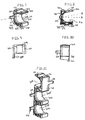
- FIGS. 1-5 show various different views of a vertical entry stackable cable management retainer 100, that, for example, could be commonly used in a ladder rack application.
- the cable retainer 100 generally has a substantially cube-shaped body 101 with three substantially planar sides 102, 104, 106 and one curvilinear U-shaped side 108.
- the two parallel side walls 102, 104 make up a vertical component and have facing latching components 110, 112, respectively, opposed at the upper extent of each side wall.
- a lower horizontally oriented bottom wall 106 joins the parallel sidewalls 102, 104 and forms the bottom of the device.
- a retention post extension 114 Located adjacent the interface of the bottom wall 106 and the front face of the cable retainer is a retention post extension 114, which is attached to the body 101 and extends in the direction of the front face a certain distance and then depends downward.
- This retention post extension 114 allows a conventional cable tie to be wrapped around the retention post extension and a wire or cable bundle to secure in place the wire or cable bundle that were previously placed within the trough 118.
- the small downward projection 116 at the end of the retention post extension 114 prevents the cable tie from being disassociated with the cable retainer 100 when the cable bundle is placed under any type of load.
- a substantially curvilinear U-shaped top wall 108 of the cable retainer 100 extends vertically downward into the body of the cable retainer 100 forming a cable trough 118.
- the trough 118 extends along a longitudinal axis A that is parallel to the direction in which the retention post extension 114 extends.
- the trough 118 is symmetric with respect to a plane H that is perpendicular to the bottom of the trough 118 defined by wall 108 as shown in FIGS. 3 and 4.
- a bundle of wires or cables are placed therein and secured as previously described above.
- Two cable tie slots 120, 122 extend through the cable retainer body 124 from the front face to the back face in parallel axial alignment with the retention post extension 114 to provide securement for the cable retainer 100 to a substrate, ladder rack or other foundation.
- conventional cable ties may be guided through the slots 120, 122 and manipulated in a conventional attachment manner in order to provide positive securement of the cable retainer 100 to a substrate.
- subsequent cable retainers 100 may be stacked one atop the other such that the latch structure 126 disposed atop each side wall 102, 104 interlockingly engages in a non-rotational manner the complimentary latch structure 128 disposed at the bottom of each side wall 102, 104.
- the troughs 118 are aligned with each other, do not face one another and are symmetric to the common plane H that is perpendicular to the bottoms of the troughs 118 as shown in FIG. 6.
- the bottom wall 106 of the upper cable retainer 100 closes off the opening formed by the trough 118 of the lower cable retainer 100.
- a series of cable retainers 100 may be securely stacked on a substrate to mount a plurality of bundles adjacent thereto in a secure fashion.
- FIGS. 7-10 Another embodiment of the stackable cable management retainer similar to the above embodiment, which can also be used in ladder rack applications, is shown in FIGS. 7-10.
- the various views of FIGS. 7-10 show that this embodiment of cable retainer 200 generally possesses many of the similar structural and functional features of the previous vertical entry retainer described above with respect to FIGS. 1-6, while providing a side entry or loading action.
- the cable retainer 200 of the second embodiment is substantially a cube-shaped body 201 having a side wall 202 and substantially horizontally planar top and bottom walls 204 and 206, respectively, which are joined by the vertically oriented substantially planar side wall 202.
- Bundle access is from the opposite curvilinearly U-shaped side wall 208 which is disposed on an axis B at a slight angle to a horizontal plane H forming a cable trough 210 as shown in FIG. 8.
- the trough 210 is asymmetric with respect to the plane H that is perpendicular to the bottom of the trough 210 defined by wall 208 as shown in FIG. 8.
- the trough 210 extends along a longitudinal axis A that is parallel to the direction that the retention post extension 214 extends.
- the bottom wall 206 has a cable tie slot 212 centrally oriented and extending through the cable retainer 200 parallel to axis A so that a conventional cable tie may be used to attach the cable retainer 200 to a substrate as described in detail above. Also, located extending outwardly from the planar cable retainer side 202 is a retention post extension 214 which is structurally and functionally identical to the retention post extension 114 described in FIG. 1.
- a latch structure that includes two substantially triangularly-shaped and parallel oriented alignment locating device projections 216. These device projections 216 are used when the subsequent retainers 200 are stacked on top of one another as shown in FIG. 11 and do not extend across the width of the top wall 204. These alignment locating device projections 216 are correspondingly received in a non-rotational manner in a latch structure that includes two areas 218 formed in the bottom wall 206 adjacent respective corners of the cable retainer 200 which are complimentarily inversely triangularly shaped and possess two small latches disposed therein. Cooperation between the projections 216 and the areas 218 locks one cable retainer 200 to another.
- the cable retainers 200 can be attached so that their troughs 208 face in the same direction while still not facing each other.
- the cable retainers 200 can also be attached so that their troughs face in opposite directions while still not facing one another.
- the orientation of the retention post extension 214 may be swapped end for end depending upon the application.
- One advantage to this embodiment is the care with which cable bundle changes may be made, in other words, the stacked assembly does not need to be separated in order to removed a single cable bundle from the middle of a stack. This is so because each of the troughs 208 is open or exposed since their openings are not enclosed by the structure of adjoining cable retainers as is the case with the stacked cable retainers of FIG. 6.
- FIGS. 12-14 An additional embodiment of a cable retainer 300 is shown in FIGS. 12-14 that shows a multiple cable installation format similar to that shown in FIG. 1.
- each of the troughs 312 is symmetric with respect to the plane H that is perpendicular to the bottom of the trough 312 as shown in FIG. 13.
- each of the troughs 312 extends along a longitudinal axis A that is parallel to the direction that the retention post extensions 310 extend.
- a single centrally located latch structure such as channels 302
- the corresponding latch structure such as distal ends 306, disposed above the centrally oriented vertical rib member 308.
- the triangularly-shaped distal ends 306 of the two outer vertical rib members 308 are aligned with and inserted into the correspondingly shaped receiving channels 302 until the distal ends 306 and the channels 302 interlockingly engage one another in a non-rotational manner without relative movement between the adjacent cable retainers 300.
- a number of multiple cable retainers may be stacked one upon another in a manner similar to the stacking shown in FIG. 6.
- a retention post extension 310 is provided for each cable trough 312 to secure the associated cable bundle in position.
- Cable tie slots 314 are also provided so that the base of the cable retainer 300 may be adequately secured to a substrate.
Landscapes
- Engineering & Computer Science (AREA)
- General Engineering & Computer Science (AREA)
- Architecture (AREA)
- Civil Engineering (AREA)
- Structural Engineering (AREA)
- Mechanical Engineering (AREA)
- Installation Of Indoor Wiring (AREA)
- Supports For Pipes And Cables (AREA)
Abstract
Description
Claims (38)
- A cable retainer comprising:a body with a trough formed therein that extends along a longitudinal axis;a retention post extension that is attached to and extends away from said body along a direction that is parallel to said longitudinal axis.
- The cable retainer of claim 1, wherein said retention post extension comprises a downward projection.
- The cable retainer of claim 1, wherein said body comprises:a first wall;a second wall parallel to said first side wall; anda third wall joining said first wall to said second wall.
- The cable retainer of claim 1, wherein said trough is formed from a U-shaped side.
- The cable retainer of claim 4, wherein said U-shaped side is a top wall.
- The cable retainer of claim 4, wherein said U-shaped side is a side wall.
- The cable retainer of claim 5, wherein said first wall comprises a first latching component and said second wall comprises a second latching component that opposes said first latching component.
- The cable retainer of claim 1, wherein said retention post extension is located adjacent an interface of said third wall and a face of said cable retainer.
- The cable retainer of claim 1, wherein a slot is formed in said body that extends parallel to said longitudinal axis.
- The cable retainer of claim 1, wherein said body comprises:a first latch structure; anda second latch structure that is complementary to said first latch structure.
- The cable retainer of claim 10, wherein said first latch structure comprises a triangularly-shaped projection.
- The cable retainer of claim 1, wherein said trough is symmetric with respect to a plane that is perpendicular to a bottom of said trough.
- The cable retainer of claim 4, wherein said trough is symmetric with respect to a plane that is perpendicular to a bottom of said trough.
- The cable retainer of claim 1, wherein said trough is asymmetric with respect to a plane that is perpendicular to a bottom of said trough.
- The cable retainer of claim 4, wherein said trough is asymmetric with respect to a plane that is perpendicular to a bottom of said trough.
- A method of retaining a cable comprising:providing a cable retainer comprising:a body with a trough formed therein that extends along a longitudinal axis; anda retention post extension that is attached to and extends away from said body along a direction that is parallel to said longitudinal axis;placing a cable within said trough; andwrapping a cable tie around said cable and said retention post extension.
- The method of claim 16, further comprising preventing said cable tie from being disassociated with said cable retainer when said cable is placed under any type of load.
- A cable retainer comprising:a first body comprising:a first trough formed therein that extends along a longitudinal axis; anda first latch structurea second body comprising:wherein said second trough does not face any troughs formed in said first body.a second trough formed therein that extends parallel to said longitudinal axis and faces said first body; anda second latch structure that is complementary to and engages said second latch structure in a non-rotational manner;
- The cable retainer of claim 18, wherein said second trough is aligned with said first trough.
- The cable retainer of claim 19, wherein said first and said second troughs are symmetric with respect to a common plane that is perpendicular to a bottom of said first trough.
- The cable retainer of claim 19, wherein said first trough faces in a direction that is opposite to the direction in which said second trough faces.
- The cable retainer of claim 19, wherein said first trough is closed by said second body.
- The cable retainer of claim 19, wherein said first trough and said second trough are open.
- The cable retainer of claim 19, wherein said first latch structure comprises a triangularly-shaped projection.
- The cable retainer of claim 19, further comprising a retention post extension that is attached to and extends away from said first body along a direction that is parallel to said longitudinal axis.
- The cable retainer of claim 25, wherein said retention post extension comprises a downward projection.
- The cable retainer of claim 19, wherein said trough is asymmetric with respect to a plane that is perpendicular to a bottom of said trough.
- The cable retainer of claim 21, wherein said trough is asymmetric with respect to a plane that is perpendicular to a bottom of said trough.
- A cable retainer comprising:a first body comprising:a first trough formed therein that extends along a longitudinal axis; anda first latch structure;a retention post extension that is attached to and extends away from said first body along a direction that is parallel to said longitudinal axis;a second body comprising:wherein said second trough does not face said first trough.a second trough formed therein that extends parallel to said longitudinal axis; anda second latch structure that is complementary to and engages said second latch structure;
- The cable retainer of claim 29, wherein said second trough is aligned with said first trough.
- The cable retainer of claim 30, wherein said first and said second troughs are symmetric with respect to a common plane that is perpendicular to a bottom of said first trough.
- The cable retainer of claim 30, wherein said first trough faces in a direction that is opposite to the direction in which said second trough faces.
- The cable retainer of claim 30, wherein said first trough is closed by said second body.
- The cable retainer of claim 30, wherein said first trough and said second trough are open.
- The cable retainer of claim 30, wherein said first latch structure comprises a triangularly-shaped projection.
- The cable retainer of claim 29, wherein said retention post extension comprises a downward projection.
- The cable retainer of claim 29, wherein said trough is asymmetric with respect to a plane that is perpendicular to a bottom of said trough.
- The cable retainer of claim 32, wherein said trough is asymmetric with respect to a plane that is perpendicular to a bottom of said trough.
Applications Claiming Priority (2)
| Application Number | Priority Date | Filing Date | Title |
|---|---|---|---|
| US13951799P | 1999-06-16 | 1999-06-16 | |
| US139517P | 1999-06-16 |
Publications (2)
| Publication Number | Publication Date |
|---|---|
| EP1061302A1 true EP1061302A1 (en) | 2000-12-20 |
| EP1061302B1 EP1061302B1 (en) | 2003-12-17 |
Family
ID=22487050
Family Applications (1)
| Application Number | Title | Priority Date | Filing Date |
|---|---|---|---|
| EP00112702A Expired - Lifetime EP1061302B1 (en) | 1999-06-16 | 2000-06-15 | Cable retainer |
Country Status (3)
| Country | Link |
|---|---|
| US (1) | US6378811B1 (en) |
| EP (1) | EP1061302B1 (en) |
| DE (1) | DE60007228T2 (en) |
Cited By (3)
| Publication number | Priority date | Publication date | Assignee | Title |
|---|---|---|---|---|
| WO2013056018A3 (en) * | 2011-10-14 | 2013-08-29 | Heyco, Inc. | Cable holder |
| CN103851269A (en) * | 2012-12-06 | 2014-06-11 | Trw车辆电气与零件有限公司 | Fixing clip and fixing component |
| EP3150444A1 (en) * | 2015-10-02 | 2017-04-05 | Amazonen-Werke H. Dreyer GmbH & Co. KG | Leitungshalter |
Families Citing this family (53)
| Publication number | Priority date | Publication date | Assignee | Title |
|---|---|---|---|---|
| DE10307835B3 (en) * | 2003-02-25 | 2004-09-16 | A. Raymond & Cie | cable clamp |
| US6706969B1 (en) * | 2003-03-31 | 2004-03-16 | Ken Young | Cable supporting and spacing device |
| US8074943B2 (en) * | 2003-10-17 | 2011-12-13 | Martin Boudreau | Pipe protector |
| US7119280B1 (en) | 2003-11-24 | 2006-10-10 | Extreme Networks, Inc. | System and method for cable management on rack mounted installations |
| US7622682B2 (en) * | 2006-01-31 | 2009-11-24 | Allied Bolt, Inc. | System and method for securing electrical cable using manually linkable cable fastening clips |
| DE102007060030B4 (en) * | 2007-06-01 | 2013-10-31 | Airbus Operations Gmbh | Aerial or spacecraft with a device for supporting systems |
| US8342474B2 (en) * | 2008-03-07 | 2013-01-01 | The Gates Corporation | Modular support, assemblies, methods and systems |
| US20090314903A1 (en) * | 2008-06-20 | 2009-12-24 | Zahuranec Terry L | Pipe clamps |
| US7734139B2 (en) * | 2008-10-07 | 2010-06-08 | Cisco Technology, Inc. | Modular cable-management system |
| US8074945B2 (en) * | 2008-12-15 | 2011-12-13 | Caterpillar Inc. | Conduit mounting system |
| US8596588B1 (en) | 2009-02-06 | 2013-12-03 | Viable Inc. | Cable and wire management device |
| US20100258684A1 (en) * | 2009-04-14 | 2010-10-14 | Guillaume Hugo Marquis-Martin | Support for tubing and method of using same |
| US8431823B2 (en) * | 2011-03-01 | 2013-04-30 | Dell Products L.P. | Cable management and identification device |
| US8985532B2 (en) * | 2011-10-19 | 2015-03-24 | Agco Corporation | Modular boom mounting system for agriculture sprayer |
| US9337636B2 (en) * | 2012-06-19 | 2016-05-10 | Frank Notaro | Modular fastening system |
| DE202013102811U1 (en) * | 2012-11-07 | 2014-02-11 | Uponor Innovation Ab | Cascadable tube holder and modular tube holding system |
| US8807492B2 (en) * | 2013-01-11 | 2014-08-19 | Western Oilfields Supply Company | Pipe crib-block |
| WO2016048374A1 (en) | 2014-09-26 | 2016-03-31 | Hewlett Packard Enterprise Development Lp | Receptacle for connecting a multi-lane or one-lane cable |
| US9517564B1 (en) * | 2014-12-29 | 2016-12-13 | Google Inc. | Fiber clamp with attachment accessory nub and receptacle |
| WO2016133499A1 (en) | 2015-02-18 | 2016-08-25 | Hewlett Packard Enterprise Development Lp | Pull-tabs for disengaging a cable assembly from a receptacle |
| WO2016137485A1 (en) * | 2015-02-27 | 2016-09-01 | Hewlett Packard Enterprise Development Lp | Cable assembly with conjoined one-lane cable assemblies |
| US10389068B2 (en) | 2015-04-29 | 2019-08-20 | Hewlett Packard Enterprise Development Lp | Multiple cable housing assembly |
| USD795047S1 (en) | 2016-02-20 | 2017-08-22 | Underground Devices, Inc. | Duct spacer |
| USD795046S1 (en) | 2016-02-20 | 2017-08-22 | Underground Devices, Inc. | Duct spacer |
| USD795048S1 (en) | 2016-02-20 | 2017-08-22 | Underground Devices, Inc. | Duct spacer |
| USD794433S1 (en) | 2016-02-20 | 2017-08-15 | Underground Devices, Inc. | Duct spacer |
| USD794434S1 (en) | 2016-02-20 | 2017-08-15 | Underground Devices, Inc. | Duct spacer |
| USD772045S1 (en) * | 2016-06-18 | 2016-11-22 | Underground Devices, Inc. | Spacer |
| USD771478S1 (en) * | 2016-06-18 | 2016-11-15 | Underground Devices, Inc. | Spacer |
| USD772047S1 (en) * | 2016-06-18 | 2016-11-22 | Underground Devices, Inc. | Spacer |
| USD772050S1 (en) * | 2016-06-18 | 2016-11-22 | Underground Devices, Inc. | Spacer |
| USD772044S1 (en) * | 2016-06-18 | 2016-11-22 | Underground Devices, Inc. | Spacer |
| USD772046S1 (en) * | 2016-06-18 | 2016-11-22 | Underground Devices, Inc. | Spacer |
| USD772048S1 (en) * | 2016-06-18 | 2016-11-22 | Underground Devices, Inc. | Spacer |
| USD772049S1 (en) * | 2016-06-18 | 2016-11-22 | Underground Devices, Inc. | Spacer |
| JP6685219B2 (en) * | 2016-12-22 | 2020-04-22 | 株式会社栗本鐵工所 | Tube pillows, pedestals and spacers for tube pillows |
| USD811855S1 (en) | 2017-05-05 | 2018-03-06 | Agile Oilfield Services, Llc | Bar for elongated members |
| USD796303S1 (en) | 2017-05-05 | 2017-09-05 | Agile Oilfield Services, Llc | Bar for elongated members |
| USD829535S1 (en) * | 2017-07-06 | 2018-10-02 | 308, Llc | Junction box |
| USD826032S1 (en) * | 2017-08-31 | 2018-08-21 | Nzxt Inc. | Cable managing device for case |
| US9949393B1 (en) * | 2017-08-31 | 2018-04-17 | Nzxt Inc. | Cable managing device for case |
| USD826034S1 (en) * | 2017-08-31 | 2018-08-21 | Nzxt Inc. | Cable managing devise for case |
| USD826033S1 (en) * | 2017-08-31 | 2018-08-21 | Nzxt Inc. | Cable managing devise for case |
| USD826700S1 (en) * | 2017-08-31 | 2018-08-28 | Nzxt Inc. | Cable managing device for case |
| USD822459S1 (en) * | 2017-09-05 | 2018-07-10 | Yanegijutsukenkyujo Co., Ltd. | Wiring-piping material fixture for fixing wires or pipes of a rooftop article |
| US20210016696A1 (en) * | 2019-07-15 | 2021-01-21 | Lear Corporation | Connected seat clip |
| US11662041B2 (en) | 2019-07-29 | 2023-05-30 | Erico International Corporation | Support clip |
| US11519541B2 (en) * | 2020-03-27 | 2022-12-06 | Pall Corporation | Tube retainers, tube retainer sets, and tube management systems |
| US11433844B2 (en) * | 2020-10-21 | 2022-09-06 | Ford Global Technologies, Llc | Bracket for a pillar assembly |
| FR3127647B1 (en) * | 2021-09-29 | 2026-01-16 | Airbus Operations Sas | METHOD AND SYSTEM FOR GUIDING A DOUBLE CURVE HOSE COLLAR |
| US20240208436A1 (en) * | 2022-12-21 | 2024-06-27 | Oshkosh Corporation | Cable holder for a vehicle |
| US12338923B2 (en) | 2023-04-14 | 2025-06-24 | Joseph Rutkowski | Data cable retaining post |
| US20260102900A1 (en) * | 2024-10-10 | 2026-04-16 | Jonathan Hurley | Modular tool organizer |
Citations (7)
| Publication number | Priority date | Publication date | Assignee | Title |
|---|---|---|---|---|
| EP0191480A2 (en) * | 1985-02-14 | 1986-08-20 | UNIMA Maschinenbau GmbH | Brackets for pipes, hoses or the like |
| US4779828A (en) * | 1986-08-16 | 1988-10-25 | Rittal-Werk Rudolf Loh Gmbh & Co. Kg | Detachable clamping bracket |
| EP0486442A1 (en) * | 1990-11-13 | 1992-05-20 | TELEPLAST S.r.L. | A system of modular supports made up of three or more pieces, suitable for receiving ducts of different diameters |
| FR2678704A1 (en) * | 1991-07-04 | 1993-01-08 | Aerospatiale | Device for supporting elongate objects |
| EP0555550A1 (en) * | 1992-02-14 | 1993-08-18 | Hermann Kleinhuis GmbH. & Co. KG | Snap-in pipe clamp for electrical installations |
| US5663527A (en) * | 1994-10-18 | 1997-09-02 | Artwright Technology Sdn Bhd | Stackable conduits with hook and hole clip means |
| FR2764361A1 (en) * | 1997-06-04 | 1998-12-11 | Quintela | Double strap support for surface pipes or cables in domestic applications |
Family Cites Families (20)
| Publication number | Priority date | Publication date | Assignee | Title |
|---|---|---|---|---|
| US1804416A (en) | 1927-07-09 | 1931-05-12 | United Advertising Corp | Pipe hanger for electrical conduits and the like |
| US3051424A (en) | 1959-09-28 | 1962-08-28 | Duhamel Gerard | Pipe hanger |
| US3523667A (en) | 1968-02-07 | 1970-08-11 | Continental Oil Co | Conduit spacer |
| US3526934A (en) | 1968-08-20 | 1970-09-08 | David H Owen Sr | Interlocking spacers |
| US3590752A (en) * | 1969-02-19 | 1971-07-06 | Thomas N De Pew | Loading rack |
| US3765629A (en) | 1971-04-16 | 1973-10-16 | Standard Oil Co | Conduit support and spacer means |
| US3856246A (en) * | 1972-05-19 | 1974-12-24 | Underground Prod Inc | Conduit spacer modular construction |
| FR2260199B1 (en) | 1974-02-05 | 1977-03-04 | Elhyco Ag | |
| US3964707A (en) | 1974-12-23 | 1976-06-22 | Lewis Gerald F | Underground conduit holder |
| DE2613745A1 (en) * | 1976-03-31 | 1977-10-06 | Linde Ag | HEAT EXCHANGER |
| DE2624333C2 (en) * | 1976-05-31 | 1984-07-05 | Hilti Ag, Schaan | clamp |
| US4199070A (en) | 1977-02-15 | 1980-04-22 | Magnussen Robert O Jr | Modular rack |
| US4195732A (en) | 1978-02-28 | 1980-04-01 | Great Northern Corporation | Supporting and spacing member for web material rolls |
| US4244542A (en) * | 1978-06-04 | 1981-01-13 | Mathews Lyle H | Conduit spacer system |
| US4306697A (en) | 1980-06-16 | 1981-12-22 | Mathews Lyle H | Conduit spacer system |
| US4395009A (en) | 1981-05-28 | 1983-07-26 | The Boeing Company | Raceway clamp |
| GB2165099A (en) * | 1984-09-26 | 1986-04-03 | Chan Hua Kuo | Conduit support block assembly |
| DE3824197A1 (en) * | 1988-07-16 | 1990-01-18 | Theodor Stratmann | Pipe clamp |
| US4942967A (en) * | 1989-08-14 | 1990-07-24 | Schneider Bernardus J J A | Bottle rack component and assembly |
| US5791607A (en) * | 1997-02-13 | 1998-08-11 | Thibault; Jean Pierre | Pipe support system |
-
2000
- 2000-06-13 US US09/592,768 patent/US6378811B1/en not_active Expired - Lifetime
- 2000-06-15 DE DE60007228T patent/DE60007228T2/en not_active Expired - Lifetime
- 2000-06-15 EP EP00112702A patent/EP1061302B1/en not_active Expired - Lifetime
Patent Citations (7)
| Publication number | Priority date | Publication date | Assignee | Title |
|---|---|---|---|---|
| EP0191480A2 (en) * | 1985-02-14 | 1986-08-20 | UNIMA Maschinenbau GmbH | Brackets for pipes, hoses or the like |
| US4779828A (en) * | 1986-08-16 | 1988-10-25 | Rittal-Werk Rudolf Loh Gmbh & Co. Kg | Detachable clamping bracket |
| EP0486442A1 (en) * | 1990-11-13 | 1992-05-20 | TELEPLAST S.r.L. | A system of modular supports made up of three or more pieces, suitable for receiving ducts of different diameters |
| FR2678704A1 (en) * | 1991-07-04 | 1993-01-08 | Aerospatiale | Device for supporting elongate objects |
| EP0555550A1 (en) * | 1992-02-14 | 1993-08-18 | Hermann Kleinhuis GmbH. & Co. KG | Snap-in pipe clamp for electrical installations |
| US5663527A (en) * | 1994-10-18 | 1997-09-02 | Artwright Technology Sdn Bhd | Stackable conduits with hook and hole clip means |
| FR2764361A1 (en) * | 1997-06-04 | 1998-12-11 | Quintela | Double strap support for surface pipes or cables in domestic applications |
Cited By (7)
| Publication number | Priority date | Publication date | Assignee | Title |
|---|---|---|---|---|
| WO2013056018A3 (en) * | 2011-10-14 | 2013-08-29 | Heyco, Inc. | Cable holder |
| US8950712B2 (en) | 2011-10-14 | 2015-02-10 | Heyco, Inc. | Cable holder |
| CN103851269A (en) * | 2012-12-06 | 2014-06-11 | Trw车辆电气与零件有限公司 | Fixing clip and fixing component |
| EP2741385A3 (en) * | 2012-12-06 | 2015-03-11 | TRW Automotive Electronics & Components GmbH | Fixing clip and fixing component |
| CN103851269B (en) * | 2012-12-06 | 2018-01-05 | 伊利诺斯工具制品有限公司 | Anchorage clip and fastening assembly |
| US10148075B2 (en) | 2012-12-06 | 2018-12-04 | Illinois Tool Works Inc. | Fastening clip and fastening assembly |
| EP3150444A1 (en) * | 2015-10-02 | 2017-04-05 | Amazonen-Werke H. Dreyer GmbH & Co. KG | Leitungshalter |
Also Published As
| Publication number | Publication date |
|---|---|
| US6378811B1 (en) | 2002-04-30 |
| DE60007228D1 (en) | 2004-01-29 |
| EP1061302B1 (en) | 2003-12-17 |
| DE60007228T2 (en) | 2004-09-16 |
Similar Documents
| Publication | Publication Date | Title |
|---|---|---|
| US6378811B1 (en) | Cable retainer | |
| US6118075A (en) | Stackable universal pitch cable trough system | |
| US4290664A (en) | Multiple outlet telephone line adapter | |
| AU637749B2 (en) | Assemblies for mounting connectors | |
| CN101304166B (en) | Protector | |
| JP2801100B2 (en) | Optical connection cassette | |
| US4758182A (en) | Electric connector | |
| US5869785A (en) | Wire clamp with parallel gripping action | |
| US6964588B2 (en) | Vertical cable management system with ribcage structure | |
| EP0919756B1 (en) | Improved cable tie having a locking head and a separate strap | |
| US6631875B1 (en) | Cable trough with separate side elements | |
| EP0913890A2 (en) | Multi-exit strain relief for an electrical connector | |
| US7896668B2 (en) | Electrical connector assembly with a detachable wire routing cover | |
| JPH04210108A (en) | Tie head | |
| WO2018151613A1 (en) | Aerial cable spacer | |
| US3848840A (en) | Plastic clamping ridged strap | |
| US5663527A (en) | Stackable conduits with hook and hole clip means | |
| US6494414B2 (en) | Retainer device for conductors in an electrical raceway | |
| GB1595798A (en) | Connector construction and mounting means and hoods therefor | |
| EP2826101B1 (en) | Electrical connector | |
| US5351391A (en) | Tool for assembling modular header connectors and modular receptacle connectors | |
| US6422781B1 (en) | Spacer coupler | |
| US20200154179A1 (en) | Extendable patch panel | |
| CN211872734U (en) | Novel roadblock convenient to stable connection | |
| JP3236165B2 (en) | Optical fiber cable storage case |
Legal Events
| Date | Code | Title | Description |
|---|---|---|---|
| PUAI | Public reference made under article 153(3) epc to a published international application that has entered the european phase |
Free format text: ORIGINAL CODE: 0009012 |
|
| AK | Designated contracting states |
Kind code of ref document: A1 Designated state(s): DE FR GB IT |
|
| AX | Request for extension of the european patent |
Free format text: AL;LT;LV;MK;RO;SI |
|
| 17P | Request for examination filed |
Effective date: 20010430 |
|
| AKX | Designation fees paid |
Free format text: DE FR GB IT |
|
| 17Q | First examination report despatched |
Effective date: 20011214 |
|
| GRAH | Despatch of communication of intention to grant a patent |
Free format text: ORIGINAL CODE: EPIDOS IGRA |
|
| GRAS | Grant fee paid |
Free format text: ORIGINAL CODE: EPIDOSNIGR3 |
|
| GRAA | (expected) grant |
Free format text: ORIGINAL CODE: 0009210 |
|
| AK | Designated contracting states |
Kind code of ref document: B1 Designated state(s): DE FR GB IT |
|
| REG | Reference to a national code |
Ref country code: GB Ref legal event code: FG4D |
|
| REF | Corresponds to: |
Ref document number: 60007228 Country of ref document: DE Date of ref document: 20040129 Kind code of ref document: P |
|
| ET | Fr: translation filed | ||
| PLBE | No opposition filed within time limit |
Free format text: ORIGINAL CODE: 0009261 |
|
| STAA | Information on the status of an ep patent application or granted ep patent |
Free format text: STATUS: NO OPPOSITION FILED WITHIN TIME LIMIT |
|
| 26N | No opposition filed |
Effective date: 20040920 |
|
| PGFP | Annual fee paid to national office [announced via postgrant information from national office to epo] |
Ref country code: IT Payment date: 20070614 Year of fee payment: 8 |
|
| PG25 | Lapsed in a contracting state [announced via postgrant information from national office to epo] |
Ref country code: IT Free format text: LAPSE BECAUSE OF NON-PAYMENT OF DUE FEES Effective date: 20080615 |
|
| PGFP | Annual fee paid to national office [announced via postgrant information from national office to epo] |
Ref country code: FR Payment date: 20090710 Year of fee payment: 10 |
|
| REG | Reference to a national code |
Ref country code: FR Ref legal event code: ST Effective date: 20110228 |
|
| PG25 | Lapsed in a contracting state [announced via postgrant information from national office to epo] |
Ref country code: FR Free format text: LAPSE BECAUSE OF NON-PAYMENT OF DUE FEES Effective date: 20100630 |
|
| PGFP | Annual fee paid to national office [announced via postgrant information from national office to epo] |
Ref country code: GB Payment date: 20110628 Year of fee payment: 12 |
|
| PGFP | Annual fee paid to national office [announced via postgrant information from national office to epo] |
Ref country code: DE Payment date: 20110629 Year of fee payment: 12 |
|
| GBPC | Gb: european patent ceased through non-payment of renewal fee |
Effective date: 20120615 |
|
| REG | Reference to a national code |
Ref country code: DE Ref legal event code: R119 Ref document number: 60007228 Country of ref document: DE Effective date: 20130101 |
|
| PG25 | Lapsed in a contracting state [announced via postgrant information from national office to epo] |
Ref country code: GB Free format text: LAPSE BECAUSE OF NON-PAYMENT OF DUE FEES Effective date: 20120615 Ref country code: DE Free format text: LAPSE BECAUSE OF NON-PAYMENT OF DUE FEES Effective date: 20130101 |