EP1059960B1 - Apparatus for electroporation through microporated tissue - Google Patents
Apparatus for electroporation through microporated tissue Download PDFInfo
- Publication number
- EP1059960B1 EP1059960B1 EP99911185A EP99911185A EP1059960B1 EP 1059960 B1 EP1059960 B1 EP 1059960B1 EP 99911185 A EP99911185 A EP 99911185A EP 99911185 A EP99911185 A EP 99911185A EP 1059960 B1 EP1059960 B1 EP 1059960B1
- Authority
- EP
- European Patent Office
- Prior art keywords
- tissue
- electrodes
- electrically heated
- micropore
- probe
- Prior art date
- Legal status (The legal status is an assumption and is not a legal conclusion. Google has not performed a legal analysis and makes no representation as to the accuracy of the status listed.)
- Expired - Lifetime
Links
- 238000004520 electroporation Methods 0.000 title claims abstract description 54
- 239000013060 biological fluid Substances 0.000 claims abstract description 8
- 239000000523 sample Substances 0.000 claims description 59
- 239000004020 conductor Substances 0.000 claims description 12
- 238000003306 harvesting Methods 0.000 claims description 4
- 230000008878 coupling Effects 0.000 claims description 3
- 238000010168 coupling process Methods 0.000 claims description 3
- 238000005859 coupling reaction Methods 0.000 claims description 3
- 238000000034 method Methods 0.000 abstract description 31
- 230000000694 effects Effects 0.000 abstract description 8
- 150000001875 compounds Chemical class 0.000 abstract description 6
- 210000001519 tissue Anatomy 0.000 description 120
- 210000003491 skin Anatomy 0.000 description 27
- 210000004379 membrane Anatomy 0.000 description 15
- 239000012528 membrane Substances 0.000 description 13
- 230000008569 process Effects 0.000 description 11
- 239000012530 fluid Substances 0.000 description 9
- 210000002615 epidermis Anatomy 0.000 description 8
- 239000000126 substance Substances 0.000 description 8
- 210000004207 dermis Anatomy 0.000 description 7
- 210000003722 extracellular fluid Anatomy 0.000 description 7
- 210000000434 stratum corneum Anatomy 0.000 description 7
- 238000004458 analytical method Methods 0.000 description 6
- 230000008901 benefit Effects 0.000 description 6
- 210000004204 blood vessel Anatomy 0.000 description 6
- 210000004027 cell Anatomy 0.000 description 6
- 230000003287 optical effect Effects 0.000 description 6
- 230000035699 permeability Effects 0.000 description 6
- 230000004888 barrier function Effects 0.000 description 5
- 230000006870 function Effects 0.000 description 5
- 239000012491 analyte Substances 0.000 description 4
- 238000010586 diagram Methods 0.000 description 4
- 239000003814 drug Substances 0.000 description 4
- 230000002708 enhancing effect Effects 0.000 description 4
- 230000004907 flux Effects 0.000 description 4
- 230000002165 photosensitisation Effects 0.000 description 4
- 239000003504 photosensitizing agent Substances 0.000 description 4
- 210000000170 cell membrane Anatomy 0.000 description 3
- 201000010099 disease Diseases 0.000 description 3
- 208000037265 diseases, disorders, signs and symptoms Diseases 0.000 description 3
- 229940079593 drug Drugs 0.000 description 3
- 238000005516 engineering process Methods 0.000 description 3
- 230000035515 penetration Effects 0.000 description 3
- 239000011148 porous material Substances 0.000 description 3
- 230000035807 sensation Effects 0.000 description 3
- WFKWXMTUELFFGS-UHFFFAOYSA-N tungsten Chemical compound [W] WFKWXMTUELFFGS-UHFFFAOYSA-N 0.000 description 3
- FAPWRFPIFSIZLT-UHFFFAOYSA-M Sodium chloride Chemical compound [Na+].[Cl-] FAPWRFPIFSIZLT-UHFFFAOYSA-M 0.000 description 2
- 238000002679 ablation Methods 0.000 description 2
- 239000012867 bioactive agent Substances 0.000 description 2
- 230000004071 biological effect Effects 0.000 description 2
- 230000015572 biosynthetic process Effects 0.000 description 2
- 239000008280 blood Substances 0.000 description 2
- 210000004369 blood Anatomy 0.000 description 2
- 230000001186 cumulative effect Effects 0.000 description 2
- 238000012377 drug delivery Methods 0.000 description 2
- 230000009977 dual effect Effects 0.000 description 2
- 239000003792 electrolyte Substances 0.000 description 2
- 210000001339 epidermal cell Anatomy 0.000 description 2
- 210000002919 epithelial cell Anatomy 0.000 description 2
- 238000009472 formulation Methods 0.000 description 2
- 239000000017 hydrogel Substances 0.000 description 2
- 239000000463 material Substances 0.000 description 2
- 239000000203 mixture Substances 0.000 description 2
- 238000012544 monitoring process Methods 0.000 description 2
- 210000004400 mucous membrane Anatomy 0.000 description 2
- 230000010287 polarization Effects 0.000 description 2
- 230000004044 response Effects 0.000 description 2
- 229910052721 tungsten Inorganic materials 0.000 description 2
- 239000010937 tungsten Substances 0.000 description 2
- CURLTUGMZLYLDI-UHFFFAOYSA-N Carbon dioxide Chemical compound O=C=O CURLTUGMZLYLDI-UHFFFAOYSA-N 0.000 description 1
- 102000008186 Collagen Human genes 0.000 description 1
- 108010035532 Collagen Proteins 0.000 description 1
- 229910052691 Erbium Inorganic materials 0.000 description 1
- WQZGKKKJIJFFOK-GASJEMHNSA-N Glucose Natural products OC[C@H]1OC(O)[C@H](O)[C@@H](O)[C@@H]1O WQZGKKKJIJFFOK-GASJEMHNSA-N 0.000 description 1
- 229910052689 Holmium Inorganic materials 0.000 description 1
- 206010061218 Inflammation Diseases 0.000 description 1
- 241001465754 Metazoa Species 0.000 description 1
- 238000010521 absorption reaction Methods 0.000 description 1
- 230000009471 action Effects 0.000 description 1
- 239000013543 active substance Substances 0.000 description 1
- 230000004075 alteration Effects 0.000 description 1
- 238000003556 assay Methods 0.000 description 1
- QVGXLLKOCUKJST-UHFFFAOYSA-N atomic oxygen Chemical compound [O] QVGXLLKOCUKJST-UHFFFAOYSA-N 0.000 description 1
- 239000012620 biological material Substances 0.000 description 1
- 230000004856 capillary permeability Effects 0.000 description 1
- 229910002092 carbon dioxide Inorganic materials 0.000 description 1
- 210000002421 cell wall Anatomy 0.000 description 1
- 230000008859 change Effects 0.000 description 1
- 229920001436 collagen Polymers 0.000 description 1
- 239000013256 coordination polymer Substances 0.000 description 1
- 230000008021 deposition Effects 0.000 description 1
- 238000013461 design Methods 0.000 description 1
- 238000001035 drying Methods 0.000 description 1
- 230000002500 effect on skin Effects 0.000 description 1
- 230000005684 electric field Effects 0.000 description 1
- 230000005670 electromagnetic radiation Effects 0.000 description 1
- UYAHIZSMUZPPFV-UHFFFAOYSA-N erbium Chemical compound [Er] UYAHIZSMUZPPFV-UHFFFAOYSA-N 0.000 description 1
- 238000005530 etching Methods 0.000 description 1
- 238000010304 firing Methods 0.000 description 1
- 239000008103 glucose Substances 0.000 description 1
- KJZYNXUDTRRSPN-UHFFFAOYSA-N holmium atom Chemical compound [Ho] KJZYNXUDTRRSPN-UHFFFAOYSA-N 0.000 description 1
- 238000000338 in vitro Methods 0.000 description 1
- 238000001727 in vivo Methods 0.000 description 1
- 238000010348 incorporation Methods 0.000 description 1
- 208000015181 infectious disease Diseases 0.000 description 1
- 230000004054 inflammatory process Effects 0.000 description 1
- 230000004941 influx Effects 0.000 description 1
- 210000001365 lymphatic vessel Anatomy 0.000 description 1
- 229920002521 macromolecule Polymers 0.000 description 1
- 238000007726 management method Methods 0.000 description 1
- 239000011159 matrix material Substances 0.000 description 1
- 230000007246 mechanism Effects 0.000 description 1
- 230000004048 modification Effects 0.000 description 1
- 238000012986 modification Methods 0.000 description 1
- 238000010369 molecular cloning Methods 0.000 description 1
- 235000015097 nutrients Nutrition 0.000 description 1
- 210000000056 organ Anatomy 0.000 description 1
- 229910052760 oxygen Inorganic materials 0.000 description 1
- 239000001301 oxygen Substances 0.000 description 1
- 230000000144 pharmacologic effect Effects 0.000 description 1
- 238000007639 printing Methods 0.000 description 1
- 230000000069 prophylactic effect Effects 0.000 description 1
- 108090000623 proteins and genes Proteins 0.000 description 1
- 238000011002 quantification Methods 0.000 description 1
- 230000009467 reduction Effects 0.000 description 1
- 230000002441 reversible effect Effects 0.000 description 1
- 210000004927 skin cell Anatomy 0.000 description 1
- 239000007787 solid Substances 0.000 description 1
- 239000007790 solid phase Substances 0.000 description 1
- 239000000758 substrate Substances 0.000 description 1
- 238000001356 surgical procedure Methods 0.000 description 1
- 238000013271 transdermal drug delivery Methods 0.000 description 1
- XLYOFNOQVPJJNP-UHFFFAOYSA-N water Substances O XLYOFNOQVPJJNP-UHFFFAOYSA-N 0.000 description 1
Images


Classifications
-
- A—HUMAN NECESSITIES
- A61—MEDICAL OR VETERINARY SCIENCE; HYGIENE
- A61N—ELECTROTHERAPY; MAGNETOTHERAPY; RADIATION THERAPY; ULTRASOUND THERAPY
- A61N1/00—Electrotherapy; Circuits therefor
- A61N1/02—Details
- A61N1/04—Electrodes
- A61N1/0404—Electrodes for external use
- A61N1/0408—Use-related aspects
- A61N1/0412—Specially adapted for transcutaneous electroporation, e.g. including drug reservoirs
- A61N1/0416—Anode and cathode
-
- A—HUMAN NECESSITIES
- A61—MEDICAL OR VETERINARY SCIENCE; HYGIENE
- A61N—ELECTROTHERAPY; MAGNETOTHERAPY; RADIATION THERAPY; ULTRASOUND THERAPY
- A61N1/00—Electrotherapy; Circuits therefor
- A61N1/18—Applying electric currents by contact electrodes
- A61N1/20—Applying electric currents by contact electrodes continuous direct currents
- A61N1/30—Apparatus for iontophoresis, i.e. transfer of media in ionic state by an electromotoric force into the body, or cataphoresis
-
- A—HUMAN NECESSITIES
- A61—MEDICAL OR VETERINARY SCIENCE; HYGIENE
- A61N—ELECTROTHERAPY; MAGNETOTHERAPY; RADIATION THERAPY; ULTRASOUND THERAPY
- A61N1/00—Electrotherapy; Circuits therefor
- A61N1/18—Applying electric currents by contact electrodes
- A61N1/32—Applying electric currents by contact electrodes alternating or intermittent currents
- A61N1/325—Applying electric currents by contact electrodes alternating or intermittent currents for iontophoresis, i.e. transfer of media in ionic state by an electromotoric force into the body
-
- A—HUMAN NECESSITIES
- A61—MEDICAL OR VETERINARY SCIENCE; HYGIENE
- A61N—ELECTROTHERAPY; MAGNETOTHERAPY; RADIATION THERAPY; ULTRASOUND THERAPY
- A61N1/00—Electrotherapy; Circuits therefor
- A61N1/18—Applying electric currents by contact electrodes
- A61N1/32—Applying electric currents by contact electrodes alternating or intermittent currents
- A61N1/327—Applying electric currents by contact electrodes alternating or intermittent currents for enhancing the absorption properties of tissue, e.g. by electroporation
-
- A—HUMAN NECESSITIES
- A61—MEDICAL OR VETERINARY SCIENCE; HYGIENE
- A61N—ELECTROTHERAPY; MAGNETOTHERAPY; RADIATION THERAPY; ULTRASOUND THERAPY
- A61N1/00—Electrotherapy; Circuits therefor
- A61N1/02—Details
- A61N1/04—Electrodes
- A61N1/0404—Electrodes for external use
- A61N1/0472—Structure-related aspects
- A61N1/0476—Array electrodes (including any electrode arrangement with more than one electrode for at least one of the polarities)
Definitions
- This invention relates to an apparatus for electroporating tissue in which micropores have been formed, for collecting and monitoring biological fluid from the tissue, or for delivery of substances into the tissue.
- Electroporation of tissue is used to enhance the permeability of the tissue, to facilitate the collection from, or delivery of substances to, the tissue. Electroporation used alone for enhancing the permeability of tissue, such as skin, has limited applications and utility.
- Microporation of tissue has been proven significantly effective in the collection of fluids, such as interstitial fluid, for the purposes of quantitating an analyte in the interstitial fluid.
- the present invention provides an apparatus for microporation and electroporation of tissue as claimed in claim 1. At least one micropore is formed to a predetermined depth through a surface of the tissue; first and second electrodes are positioned spaced apart on the tissue and one of the electrodes is electrically coupled to the at least one micropore; and an electrical voltage is applied between the electrodes to produce a desired electroporation in the tissue between the electrodes.
- the electroporation electrodes also serve the function of participating in the microporation of the tissue.
- a device having elements that are suitable for microporating the tissue and electroporating the tissue is provided.
- the parameters for electroporation can be significantly adjusted and the sensation to the patient can also be reduced.
- the electroporation can be directed at selected structures in the skin tissue matrix, such as capillaries, vessels, lymphatic paths and the like, so as to enhance the forcing function of interstitial fluid from the microporated tissue, thereby facilitating the collection and analysis of the fluid.
- electroporation applied to the capillaries also increases the capillary permeability to substances which are to be delivered into the tissue.
- biological fluid is intended to include “interstitial fluid” (ISF), which is the clear fluid that occupies the space between the cells in the body.
- ISF interstitial fluid
- stratum corneum means the outermost layer of the skin, consisting of from about 15 to about 20 layers of cells in various stages of drying out. The stratum comeum provides a barrier to the loss of water from inside the body to the external environment and from attack from the external environment to the interior of the body.
- epidermis means the region of the skin including the stratum corneum and extending approximately 10 times as thick as the stratum corneum into the body, wherein the portions of the epidermis beneath the stratum corneum is comprised of living, metabolically active cells.
- the epidermis does not contain capillaries or blood vessels.
- the term "dermis" means the region of skin approximately 10 times as thick as the epidermis and found just below the epidermis.
- the dermis contains large amounts of collagen, which provides structural integrity to the skin.
- the dermis contains a layer of small blood vessels and capillaries that provide oxygen and nutrients to the rest of the layers of skin.
- tissue means an aggregate of cells of a particular kind, together with their intercellular substance, that form a structural material of an animal or plant. At least one surface of the tissue must be accessible to electromagnetic radiation so that apparatus of the invention can be used.
- the preferred tissue is the skin.
- Other tissues suitable for use with this invention include mucosal tissue and soft organs.
- poration means the formation of a small hole or pore to a desired depth in or through the biological membrane, such as skin or mucous membrane, or the outer layer of an organism to lessen the barrier properties of this biological membrane to the passage of biological fluids, such as analytes from below the surface for analysis or the passage of permeants or drugs into the body for selected purposes, or for certain medical or surgical procedures.
- the hole or micropore will be no larger than about 1 mm (1000 ⁇ m) in diameter, and will extend to a selected depth, as described hereinafter.
- biological membrane or “membrane” means any tissue material present within a living organism forming a barrier between distinct tissues or areas of an organism, or between tissue of an organism and the external environment, and includes without limitation: the skin, mucosal membranes; buccal membranes; the outer layers of a plant; and the walls of a cell or a blood vessel.
- Electroporation means a process by which electrical current is applied through tissue by electrodes spaced apart on or in the tissue to temporarily increase the permeability of the tissue membranes to collection of fluids therefrom, or delivery of permeants thereto. It involves the delivery of pulses of electrical energy of relative short duration to cause the voltage potential developed across the targeted tissue structure to be sufficiently greater than a threshold level to produce the desired electroporation.
- the parameters typical of electroporation and the thresholds for effective operation under many operating conditions are well known in the art, and are discussed in several articles, including "Electroporation Of Mammalian Skin: A Mechanism to Enhance Transdermal Drug Delivery,” Proc. Nat'l Acad. Sci.
- micropore or "pore” means an opening formed by the microporation method.
- bioactive agent means any chemical biological material or compound suitable for delivery by the methods previously known in the art and/or by the methods taught herein, that induces a desired effect, such as a biological or pharmacological effect, which may include but is not limited to (1) having a prophylactic effect on the organism and preventing an undesired biological effect such as preventing an infection, (2) alleviating a condition caused by a disease, for example, alleviating pain or inflammation caused as a result of disease, (3) either alleviating, reducing, or completely eliminating the disease from the organism, and/or (4) the placement within the viable tissue layers of the organism of a compound or formulation which can react, optionally in a reversible manner, to changes in the concentration of a particular analyte and in so doing cause a detectable shift in this compound or formulation's measurable response to the application of energy to this area which may be electromagnetic, mechanical
- heated probe means a probe, preferably solid phase, which is capable of being heated in response to the application of electrical or electromagnetic (optical) energy thereto.
- the probe is referred to as a “heated probe” which includes a probe in a heated or unheated state, but which is heatable.
- the present invention is directed to apparatus for creating an electroporation effect to selectively enhance the permeability of selected structures within tissue, including but not limited to, cell membrane walls, the membranes separating different tissue types and the walls of the capillaries and blood vessels present in the dermis, to allow a greater out-flux of the aqueous fluid from within the blood volume into the interstitial spaces or to allow a greater influx of a compound introduced into these surrounding tissues and hence the blood stream.
- This method may be used in conjunction with additional permeation enhancement measures of the skin tissues to facilitate the external collection of a volume of interstitial fluid sufficient to allow an assay to be run on the interstitial fluid for the quantification of a selected analyte, such as glucose, or for the delivery of a permeant into the body.
- a selected analyte such as glucose
- the physical size of the capillary and vessel cross-section is several times larger than the dermal and epidermal cells also present in the current path, and the potential drop across all of these structures is known to occur almost exclusively at the outer membrane, or in the case of the capillaries or blood vessels, at the epithelial cell layer comprising the main barrier structure within the wall of the capillary or vessel. Consequently, a current density sufficient to produce a potential drop exceeding the nominal threshold (preferably greater than about 1 volt) to achieve electroporation across the epithelial cell layer is not sufficient to electroporate the membranes present in other tissue structures, such as the cell walls of the epidermal cells, through which the current is flowing, hence allowing a selective electroporation of only the targeted membranes.
- the nominal threshold preferably greater than about 1 volt
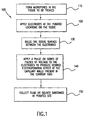
- FIG. 1 depicts the steps of the overall process 100 using an apparatus according to the present invention.
- the overall process involves forming at least one micropore to a predetermined depth range through a surface of the tissue; positioning at least a first electrode electrically coupled to the at least one micropore and a second electrode spaced apart from the first electrode; applying an electrical voltage between the first and second electrodes sufficient to produce a desired electroporation in the tissue present in the induced current path.
- Step 110 involves forming micropores in the tissue to be treated. At least one micropore is formed, though as will become more apparent hereinafter, multiple micropores may be formed.
- the micropore is formed through a surface of the tissue, such as skin, to a predetermined depth range into the tissue. For example, at least one microporation in the outer layer of the epidermis is formed to allow the high impedance layer of the stratum corneum to be eliminated from the current path.
- the depth to which a micropore is created is described in U.S. Provisional Application Serial No. 60/077,135, filed on even date, and entitled “Integrated Poration, Harvesting and Analysis Device, and Method Therefor,".
- microporation depth control is also described in U.S. Application Serial No. 09/036,053, entitled “Method and Apparatus For Enhancing Flux Rates Of A Fluid In A Microporated Biological Tissue,” filed on even date.
- micropores are formed some distance apart in the locations where the electrodes are to be placed. These micropores are created by one of the several methods such as those disclosed in the aforementioned U.S. Application Serial No. 08/776,863, and described hereinafter.
- the micropores range in size from 1 to 1000 microns across and from 20 to 1000 microns deep, but preferably 80 to 500 microns across and 40 to 180 microns deep.
- step 120 electrodes are applied or positioned (if not already in position) about the microporation(s) on the tissue.
- This step involves the mechanical positioning of at least first and second electrodes such that at least one of the electrodes is electrically coupled to the micropore. That is, at least one of the electrodes (i.e., the first electrode) is positioned proximate the micropore so that the dominant or preferred current path to that electrode, induced by the electrical voltage between it and the second electrode is through the micropore. This assists in ensuring that at least some, if not the preferred, current density paths through the tissue intersects at least some of the capillary loop structures and blood vessels present in these tissues.
- the second electrode can be coupled to any other tissue surface, acting to complete the current path through the tissue with respect to the first electrode.
- each of the first and second electrodes may be electrically coupled to micropores formed in the tissue separated from each other.
- the electrodes may electrically penetrate into the micropore through a compliant electrolyte, e.g., a conductive hydrogel or a saline solution, placed on the contacting surface to facilitate electrical contact into the micropores.
- a compliant electrolyte e.g., a conductive hydrogel or a saline solution
- Step 130 involves deforming the tissue surface so that it bows or bulges between the microporations. Depending on the depth of the micropores and the penetration of the electrode into them, a small deformation of the tissue surface into a bowed shape is created between the micropores such that a line drawn between the micropores would intersect the targeted tissue structures, such as capillaries and vessels in, for example, the dermis.
- an electrical voltage pulse or series of voltage pulses is applied between the first and second electrodes of sufficient magnitude or amplitude such that the resulting current flow through the intervening tissue, including the targeted structures causes a potential drop across these targeted tissue structures, such as capillary walls, which exceeds the electroporation threshold for these tissue structures present in the current path.
- the pulsing scheme can include the modulation of pulse amplitude, pulse timing, pulse polarity and geometrical direction of the pulses to achieve desired electroporation effects.
- the duration of the pulse is relatively short, such as(1 ⁇ s to 10 ms) with an amplitude designed to ensure that the potential drop across the targeted membrane structures in the current path nominally exceeds a 1 volt potential, the value known in the art as being the nominal threshold level at which effective poration of a membrane begins to occur.
- the pulse duration and amplitude applied to the electrodes depends on the specific tissue to which the electrodes are applied, the spacing between the electrodes, and other parameters that affect the impedance of the current path and the coupling of the electrodes to the tissue.
- step 150 biological fluid exuded from the microporated and electroporated tissue is collected for analysis, or a substance, such as a drug or other bioactive agent is delivered into the permeability-enhanced tissue.
- the apparatus comprises a heated probe suitable for conducting heat to a surface of the tissue to form at least one micropore therein; at least first and second electrodes spaced apart from each other on the tissue, with the first electrode being electrically coupled to the micropore; and control means for supplying energy to the heated element so as to form the at least one micropore, and for applying electrical voltage between the first and second electrodes for electroporating the tissue.
- the apparatus shown generally at reference numeral 200, comprises at least two electrodes 210 and 212. At least one of the electrodes is positioned in one of the micropores M1 and M2 formed through the tissue surface TS, such as skin, and the other electrode is spaced from it and placed on the tissue surface to complete the current path through the tissue. Preferably, the electrodes 210 and 212 are placed in micropores M1 and M2. The electrodes 210 and 212 may be supported by a tissue-contacting layer 214. Electrical voltage is applied between the electrodes 210 and 212 by energy supply means, included as part of a control system 220. The control system 220 includes the appropriate circuitry to supply electrical current and electrical voltage, and to control an optical energy source (if needed).
- Electrodes 210 and 212 Electrical contact of the electrodes 210 and 212 with the micropores can be achieved with a compliant electrolyte, such as a conductive hydrogel or a saline solution placed on the surface of the tissue in the micropores.
- a compliant electrolyte such as a conductive hydrogel or a saline solution placed on the surface of the tissue in the micropores.
- each electrode is preferably positioned proximate a micropore so as to be electrically coupled thereto.
- micropores M1 and M2 are formed prior to energization of the electroporation electrodes 210 and 212. These micropores may be formed in several ways, including thermal ablation via a heated probe by electrical or optical energy. Optical or laser thermal ablation involves placing a photosensitizing assembly, including an optically absorbing compound such as a dye, in contact with the surface of the tissue, optical energy is focused on the photosensitizing assembly which heats it, and the heat is transferred to the surface of the tissue, forming a micropore. The details of this technique are well described in all of the aforementioned U.S. applications.
- a source of optical energy (not shown), controlled by the control system 220, is optically coupled to the photosensitizing assembly placed on the surface of the tissue.
- the skin could be microporated using a laser which emits at a wavelength which is directly absorbed by the tissue to be removed such as an excimer, holmium, erbium, or CO2 laser or the like.
- a laser which emits at a wavelength which is directly absorbed by the tissue to be removed
- CO2 laser or the like such as an excimer, holmium, erbium, or CO2 laser or the like.
- the use of direct laser absorption to form micropores is well known in the art.
- the application of the electroporation methods which are disclosed herein are suitably compatible with those other methods for forming the micropores in the skin.
- each electrode 210 and 212 also serve as electrically heated probes used for thermally ablating the tissue to form the micropores M1 and M2.
- each electrode 210 and 212 comprises an electrically heated probe consisting of an electrically heated wire which is responsive to electrical current supplied therethrough.
- electrical current is coupled via conductor leads 222 and 224 to electrode 210 to supply an electrical current therethrough, and electrical current is also coupled via conductor lead lines 226 and 228 to electrode 212.
- the electrically heated probes described above are dual purpose in that they can perform the functions of microporation and of electroporation.
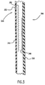
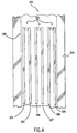
- FIGs. 3 and 4 illustrate the incorporation of dual purpose electrically heated probes as part of an integrated fluid harvesting, collection and analysis device, shown generally at reference numeral 300.
- the device 300 includes a tissue-contacting layer 310 having an electrically heated probe surface 320.
- the device 300 further comprises a detecting layer 340 such as a photometric sensor or an electrochemical biosensor, both of which are capable of providing an indication of a characteristic of a collected biological fluid, such as the level of an analyte in interstitial fluid.
- a meter (not shown) is coupled by a meter-interface layer 330, to the detecting layer 340 either electrically or optically, depending on the type of detecting layer used.
- the integrated device 300 is more fully disclosed in U.S. Application Serial No. 60/077,135, entitled "Integrated Poration, Harvesting And Analysis Device, And Method Therefor.”
- the electrically heated probe surface 320 comprises several electrically heated probes 322 provided on the bottom surface of the tissue-contacting layer 310. Three electrical heated probes 322 are shown, but any number of them may be provided. Each of the three heated probes 322 are connected to a pair of the electrical conductors 324, 325, 326, 327, 328 and 329 as shown. The electrical conductors extend the length of the tissue-contacting layer 310 and terminate at a plurality of points near the lower end of the integrated device 300. Each electrically heated probe 322 is connected to a control system by the respective pairs of conductors ⁇ 324, 325 ⁇ , ⁇ 326, 327 ⁇ and ⁇ 328, 329 ⁇ as shown in FIG. 4.
- Each electrically heated probe 322 can be activated individually through the appropriate selection and energization of the conductors 324, 325, 326, 327, 328 and 329. It may be advantageous to excite all electrically heated probes 322 simultaneously, thereby enabling either a series or parallel wiring design, reducing the number of interconnections to the device and facilitating a more rapid poration process. If only one electrically heated probe 322 is provided, then at least two conductors are provided for supplying electric current to it.
- the electrically heated probes 322 function as solid thermal probes and are electrically heated so that a temperature of the tissue, if skin, is raised to greater than 123 C.
- the electrically heated probes 322 comprise, for example a 100 to 500 micron long, 50 micron diameter, tungsten wire element.
- tungsten wire element A number of human clinical studies have been performed wherein the surface microporation was achieved by using these types of wires as the electrically heated probe.
- These tungsten elements are typically laid flat against some form of a backing which naturally limits the depth of penetration of the wire element into the tissue as it is being microporated (by virtue of the size of the element).
- the temperature of the heated element is modulated as needed to effect the microporation process.
- Such pulse duty cycle and modulation techniques are disclosed in U.S. Application Serial No. 08/776,863.
- the graph of FIG. 5 shows impedance data between two electrically heated probes (tungsten elements) spaced apart by 2.5 mm on human skin.
- the graph shows that immediately after even a first pulse is applied, the electrical impedance between them through the body's core drops by several orders of magnitude and then continues to drop with each subsequent pulse as the probe enters deeper into the viable skin tissues, making this an ideal electrode for delivering the desired electroporation pulse.
- the thermal pulses each reached a maximum of 700°C and had a duration of 3 ms.
- the inherent and perfect alignment between the electrically heated probe and the micropore it has created also simplifies the process, requiring no additional steps or hardware to position the electrode.
- the electrically heated probes 322 also function as electroporation electrodes is particularly advantageous because they are already contacting the moist viable epidermis after the microporation process has been performed. With these electrodes in place, a mild current, either DC or AC can be established from one or more electrodes to another one or more electrodes, or from one (or more) electrodes to a separate electrode by the application of a suitable voltage between the electrodes, to induce an electromagnetic force field in the ISF-laden tissues beneath the stratum corneum to enhance the outflow of the ISF sample.
- a mild current either DC or AC can be established from one or more electrodes to another one or more electrodes, or from one (or more) electrodes to a separate electrode by the application of a suitable voltage between the electrodes, to induce an electromagnetic force field in the ISF-laden tissues beneath the stratum corneum to enhance the outflow of the ISF sample.
- a similar technique can be applied with the use of an optically heated probe in an integrated device, such as that disclosed in the application filed on even date.
- additional electrodes such as those shown in the device of FIGs. 3 and 4, are additionally required in order to deliver the electroporation energy to the microporated tissue.
- These additional electrodes can be conveniently formed on the lower surface of the photosensitizing assembly or layer using a lithographic process to create a printed circuit type pattern of conductive traces, portions of which serve as the electrodes on the tissue-contacting side of this layer. This pattern of conductors registers the electrodes to the micropores to be formed, so that at least one electrode in the conductive trace is electrically coupled to a micropore.
- current flux lines EF are created, such that at least one or more of them pass through the intervening targeted tissue structures, such as the capillaries, CP in the tissue.
- These flux lines preferably go as deep as the papillary dermis so as to affect the capillaries therein.
- the voltage pulsing scheme may consist of a first voltage pulse of a polarity followed by a second voltage pulse of an opposite polarity. This causes current to flow in both directions between the electrodes.
- An advantage of redirecting the current flow in both directions at a given set of micropores is that by presenting the body with a balanced AC signal, no cumulative electrical polarization is established. This balanced signal has been shown to minimize the sensation to an individual.
- the tissue may be deformed by a predetermined amount D so as to further increase the number of electric flux lines that pass through specific targeted tissue structures, such as capillaries in the tissue.
- the tissue may be deformed by as much as 0.5 mm. This deformation could be achieved by several means. For example, the tissue could be simply squeezed together between the microporations.
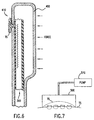
- FIG. 6 illustrates a mechanical element that can be used to impart a bow in the tissue.
- the mechanical element 400 has a small opening 410 therein (2 mm to 4 mm). Applying force to the mechanical element 400 presses the device onto the skin at the poration site and thus causes the surface of the tissue, i.e., the skin, to bow or bulge into the opening 410 and between the electrodes supported on the device 300. This bulge of the tissue enhances the effect that the current paths created during electroporation can have in the tissue, as shown in FIG. 2A. Furthermore, this induces a positive pressure gradient in the ISF, forcing the fluid towards the micropore(s) where it can exit the tissue and enter a fluid management chamber of the device.
- FIG. 7 illustrates another means of creating a bulge in the tissue.
- a vacuum chamber 500 can be created above the surface of the tissue which is to be electroporated, contained by a sealed container.
- a source or means of negative pressure, such as a pump 510 is coupled to an enclosed chamber which is sealed over the area of the tissue to be treated.
- the tissue is sucked into the chamber 500 using a mild suction, wherein the dimensions and shape of the opening to the chamber 500 and the amount of suction applied produce the desired amount of deformation of the tissue surface.
- Other suction means such as a syringe or diaphragm are also suitable.
- electroporation coupled with microporation achieves significant advantages. Specifically, in the case of conventional electroporation, where pulses exceeding 50 to 150 volts are routinely used to electroporate the stratum corneum or mucosal layer, in the microporated tissue environment of the present invention, pulses of only a few volts can be sufficient to electroporate the cell, capillary or other membranes within the targeted tissue. This is principally due to the dramatic reduction in the number of insulating layers present between the electrodes once the outer surface of the tissue has been opened, as reflected by the graph of FIG. 5.
- the manner in which the electroporation pulses are applied may vary. For example, a plurality of micropores spaced apart from each other in the tissue may be formed, and the electrical pulses are then applied in multiple directions between different sets (pairs or more) of electrodes to facilitate the electroporation of a larger percentage of the area of the targeted structures in the intervening tissue such as capillary walls.
- This multi-directional cross firing can be achieved with a plurality of electrically heated probes, similar to those shown in FIGs. 3 and 4.
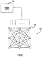
- FIG. 8 illustrates such an embodiment, in which an 3 x 3 array 600 of electrically heated probes 610 is applied to the surface of the tissue.
- the electrically heated probes 610 also serve as the electroporation electrodes.
- the array can be formed using well known circuit printing technologies, such as etching, lithographic film deposition, etc.
- a suitable electrically heated poration element is then placed onto the appropriate conductors etched onto a circuit board/substrate.
- all or selected ones of the heated probes 610 are energized to form micropores in the tissue.
- sets of the heated probes 610 which are already suitably electrically coupled to their respective micropores, are connected to a source of AC or DC voltage to create a current distribution between them. Voltage is applied between different sets of poration elements, now acting as electroporation electrodes, at the different micropores so as to change the direction of the electroporation through the tissue.
- Successive pulses are preferably either in an opposite polarity with respect to the same set of electrodes and/or are between different sets of electrodes.
- Each possible path can be energized in either polarity, or toggled back and forth between polarities.
- the advantages of redirecting the current flow in both directions at a given set of micropores is that by presenting the body with a balanced AC signal, no cumulative electrical polarization is established.
- this multi-directional current control has been shown to dramatically reduce the sensation of the subject during the electroporation process as has the setting of the pulse parameters below certain peak voltage levels and with a duration of each pulse kept to a minimum, preferably under a few milliseconds.
- electroporation can cause opening to form, temporarily, in the cell membranes and other internal tissue membranes.
- electroporation can be used with parameters tailored to act selectively on these underlying tissue barriers.
- the specific action of the enhancement can be designed to focus on any part of the micropore, e.g. on the bottom of the micropore by focusing the discharge of the electrodes, phasing of multiple electrodes or other filed forming methods and devices and the like.
- the enhancement can be focused more generally on the entire micropore or the area surrounding the pore.
- the mode of operation of electroporation when applied after the microporation of the tissue has the advantage of being able to use operational parameters which would be useless for un-microporated, intact tissue surface conditions.
- the operational settings useable when applied after the microporation of the skin or mucosal layer or the outer layer of a plant are generally close to those typically used in in vitro applications where single cell membranes are opened up for the delivery of a substance. Examples of these parameters are well known in the literature. For example, Sambvrook et al., Molecular Cloning: A Laboratory Manual, 2d Ed., Cold Spring Harbor Laboratory, Cold Spring Harbor, New York, 1989.
- Still another enhancement which may be used in conjunction with the electroporation techniques described herein is the application of sonic energy. Suitable sonic energy techniques are described in the aforementioned U.S. applications.
Landscapes
- Health & Medical Sciences (AREA)
- Life Sciences & Earth Sciences (AREA)
- Engineering & Computer Science (AREA)
- Animal Behavior & Ethology (AREA)
- Radiology & Medical Imaging (AREA)
- Nuclear Medicine, Radiotherapy & Molecular Imaging (AREA)
- Biomedical Technology (AREA)
- General Health & Medical Sciences (AREA)
- Public Health (AREA)
- Veterinary Medicine (AREA)
- Biophysics (AREA)
- Bioinformatics & Cheminformatics (AREA)
- Electrotherapy Devices (AREA)
- Manufacture Of Porous Articles, And Recovery And Treatment Of Waste Products (AREA)
- Surgical Instruments (AREA)
Abstract
Description
Claims (16)
- An apparatus for microporation and electroporation of tissue comprising: a probe (322), at least first and second electrodes (210, 212) spaced apart from each other on the tissue, and control means (220) for applying electrical voltage between the first and second electrodes (210, 212) for electroporating the tissue, said apparatus characterized by said probe (322) being a heatable probe suitable for conducting heat to a surface of the tissue to form at least one micropore thereon, and said control means (220) supplying energy to the heatable probe so as to form the at least one micropore, whereby the first electrode (210) is electrically coupled to the micropore.
- The apparatus of claim 1, wherein the electrical voltage applied between the first and second electrodes (210, 212) is of a magnitude suitable for causing a voltage drop across capillaries in the tissue which lie in a current path between the first and second electrodes to exceed an electroporation threshold.
- The apparatus of claim 1, wherein the heated probe (322) forms first and second micropores spaced apart from each other in the tissue, and wherein the first electrode (210) is electrically coupled to the first micropore and the second electrode (212) is electrically coupled to the second micropore.
- The apparatus of claim 1, wherein the heated probe (322) is an electrically heated probe, and wherein the control means (220) supplies electric current to the electrically heated probe (322) to form the at least one micropore.
- The apparatus of claim 4, wherein the electrically heated probe (322) also serves as the first electrode (210) such that the electrical voltage is applied between the electrically heated probe (322) and the second electrode (212).
- The apparatus of claim 4, wherein the heated probe (322) comprises first and second electrically heated probes spaced apart from each other each responsive to electrical current supplied by the control means (220) to form two micropores in the tissue spaced apart from each other.
- The apparatus of claim 6, wherein the first and second electrically heated probes (322) further serve as the first and second electrodes, the control means (220) being coupled to the first and second electrically heated probes (322) so as to apply the electrical voltage therebetween.
- The apparatus of claim 7, and further comprising a tissue-contacting layer (310) supporting the first and second electrically heated probes (322), and further comprising conductor means (324, 325, 326, 327, 328) for coupling electrical current from the control means (220) to the first and second electrically heated probes (322), and for applying the electrical voltage between the first and second electrically heated probes.
- The apparatus of claim 1, wherein the control means (220) applies a first voltage pulse of a polarity with respect to the first and second electrodes (210, 212), followed by a voltage pulse of an opposite polarity with respect to the first and second electrodes (210, 212).
- The apparatus of claim 1, and comprising a plurality of electrically heated probes (322) each responsive to electrical current for forming a plurality of micropores spaced apart from each other in the tissue, and wherein the control means (220) applies electrical voltage pulses between different sets of the plurality of electrically heated probes so as to electroporate the tissue in multiple directions.
- The apparatus of claim 10, wherein the control means (220) applies a voltage pulse of a first polarity between a first set of electrodes followed by a voltage pulse of an opposite polarity between the first set of electrodes.
- The apparatus of claim 1, and comprising an integrated device for harvesting, collecting and analyzing biological fluid, the integrated device comprising a tissue-contact layer and a detecting layer, wherein the heated probe and the first and second electrodes are supported by the tissue-contacting layer, the detecting layer being positioned adjacent the tissue-contacting layer for detecting a characteristic of a biological fluid collected from the tissue through the at least one micropore.
- The apparatus of claim 12, wherein the detecting layer comprises an electrochemical biosensor.
- The apparatus of claim 12, wherein the detecting layer comprises a photometric sensor.
- The apparatus of claim 1, and further comprising a mechanical element suitable for causing the surface of the tissue to bulge between the first and second electrodes.
- The apparatus of claim 1, and further comprising means for applying suction to the tissue so as to suck the surface of the tissue between the first and second electrodes.
Applications Claiming Priority (3)
| Application Number | Priority Date | Filing Date | Title |
|---|---|---|---|
| US36169 | 1998-03-06 | ||
| US09/036,169 US6022316A (en) | 1998-03-06 | 1998-03-06 | Apparatus and method for electroporation of microporated tissue for enhancing flux rates for monitoring and delivery applications |
| PCT/US1999/004984 WO1999044678A1 (en) | 1998-03-06 | 1999-03-05 | Apparatus for electroporation through microporated tissue |
Publications (2)
| Publication Number | Publication Date |
|---|---|
| EP1059960A1 EP1059960A1 (en) | 2000-12-20 |
| EP1059960B1 true EP1059960B1 (en) | 2004-12-01 |
Family
ID=21887040
Family Applications (1)
| Application Number | Title | Priority Date | Filing Date |
|---|---|---|---|
| EP99911185A Expired - Lifetime EP1059960B1 (en) | 1998-03-06 | 1999-03-05 | Apparatus for electroporation through microporated tissue |
Country Status (9)
| Country | Link |
|---|---|
| US (1) | US6022316A (en) |
| EP (1) | EP1059960B1 (en) |
| JP (1) | JP3619453B2 (en) |
| AT (1) | ATE283719T1 (en) |
| AU (1) | AU748376B2 (en) |
| CA (1) | CA2329169C (en) |
| DE (1) | DE69922353T2 (en) |
| ES (1) | ES2237091T3 (en) |
| WO (1) | WO1999044678A1 (en) |
Cited By (1)
| Publication number | Priority date | Publication date | Assignee | Title |
|---|---|---|---|---|
| WO2019237107A1 (en) * | 2018-06-08 | 2019-12-12 | Mayo Foundation For Medical Education And Research | Dermatological electroporation devices and methods |
Families Citing this family (198)
| Publication number | Priority date | Publication date | Assignee | Title |
|---|---|---|---|---|
| US20060240381A1 (en) * | 1995-08-31 | 2006-10-26 | Biolase Technology, Inc. | Fluid conditioning system |
| US20090143775A1 (en) * | 1995-08-31 | 2009-06-04 | Rizoiu Ioana M | Medical laser having controlled-temperature and sterilized fluid output |
| US7184826B2 (en) * | 1996-06-18 | 2007-02-27 | Alza Corporation | Device and method for enhancing transdermal flux of agents being delivered or sampled |
| ES2200187T3 (en) * | 1996-07-03 | 2004-03-01 | Altea Therapeutics Corporation | MULTIPLE MECHANICAL MICROPORATION OF THE SKIN OR MUCOSA. |
| US20060002959A1 (en) * | 1996-11-14 | 2006-01-05 | Government Of The United States | Skin-sctive adjuvants for transcutaneous immuization |
| US20060002949A1 (en) | 1996-11-14 | 2006-01-05 | Army Govt. Of The Usa, As Rep. By Secretary Of The Office Of The Command Judge Advocate, Hq Usamrmc. | Transcutaneous immunization without heterologous adjuvant |
| US5980898A (en) | 1996-11-14 | 1999-11-09 | The United States Of America As Represented By The U.S. Army Medical Research & Material Command | Adjuvant for transcutaneous immunization |
| US6797276B1 (en) | 1996-11-14 | 2004-09-28 | The United States Of America As Represented By The Secretary Of The Army | Use of penetration enhancers and barrier disruption agents to enhance the transcutaneous immune response |
| US20060149343A1 (en) * | 1996-12-02 | 2006-07-06 | Palomar Medical Technologies, Inc. | Cooling system for a photocosmetic device |
| US8182473B2 (en) * | 1999-01-08 | 2012-05-22 | Palomar Medical Technologies | Cooling system for a photocosmetic device |
| US6517532B1 (en) * | 1997-05-15 | 2003-02-11 | Palomar Medical Technologies, Inc. | Light energy delivery head |
| US7204832B2 (en) | 1996-12-02 | 2007-04-17 | Pálomar Medical Technologies, Inc. | Cooling system for a photo cosmetic device |
| US6527716B1 (en) | 1997-12-30 | 2003-03-04 | Altea Technologies, Inc. | Microporation of tissue for delivery of bioactive agents |
| EP0991372B1 (en) * | 1997-05-15 | 2004-08-04 | Palomar Medical Technologies, Inc. | Apparatus for dermatology treatment |
| US6241701B1 (en) | 1997-08-01 | 2001-06-05 | Genetronics, Inc. | Apparatus for electroporation mediated delivery of drugs and genes |
| US6216034B1 (en) | 1997-08-01 | 2001-04-10 | Genetronics, Inc. | Method of programming an array of needle electrodes for electroporation therapy of tissue |
| US6055453A (en) | 1997-08-01 | 2000-04-25 | Genetronics, Inc. | Apparatus for addressing needle array electrodes for electroporation therapy |
| US20050003008A1 (en) * | 1997-09-23 | 2005-01-06 | Natalya Rapoport | Method of in vivo drug targeting to solid tumors via acoustically triggered drug delivery in polymeric micelles |
| US20040258703A1 (en) * | 1997-11-14 | 2004-12-23 | The Government Of The Us, As Represented By The Secretary Of The Army | Skin-active adjuvants for transcutaneous immunization |
| US6173202B1 (en) | 1998-03-06 | 2001-01-09 | Spectrx, Inc. | Method and apparatus for enhancing flux rates of a fluid in a microporated biological tissue |
| DE69926348T2 (en) | 1998-03-12 | 2006-06-01 | Palomar Medical Technologies, Inc., Burlington | SYSTEM FOR THE ELECTROMAGNETIC IRRADIATION OF THE SKIN |
| EP2428250A1 (en) | 1998-07-13 | 2012-03-14 | Genetronics, Inc. | Skin and muscle-targeted gene therapy by pulsed electrical field |
| WO2000002620A1 (en) | 1998-07-13 | 2000-01-20 | Genetronics, Inc. | Method and apparatus for electrically assisted topical delivery of agents for cosmetic applications |
| US6678556B1 (en) | 1998-07-13 | 2004-01-13 | Genetronics, Inc. | Electrical field therapy with reduced histopathological change in muscle |
| ES2317699T3 (en) | 1998-07-14 | 2009-04-16 | Altea Therapeutics Corporation | CONTROLLED ELIMINATION OF A BIOLOGICAL MEMBRANE THROUGH A PIROTECHNICAL LOAD FOR A TRANSMEMBRANIC TRANSPORT. |
| US6602678B2 (en) | 1998-09-04 | 2003-08-05 | Powderject Research Limited | Non- or minimally invasive monitoring methods |
| ATE237277T1 (en) | 1998-09-04 | 2003-05-15 | Powderject Res Ltd | SECOND MEDICAL INDICATION OF A PARTICLE ADMINISTRATION METHOD |
| US6059820A (en) | 1998-10-16 | 2000-05-09 | Paradigm Medical Corporation | Tissue cooling rod for laser surgery |
| US6611706B2 (en) | 1998-11-09 | 2003-08-26 | Transpharma Ltd. | Monopolar and bipolar current application for transdermal drug delivery and analyte extraction |
| US6597946B2 (en) | 1998-11-09 | 2003-07-22 | Transpharma Ltd. | Electronic card for transdermal drug delivery and analyte extraction |
| US6148232A (en) * | 1998-11-09 | 2000-11-14 | Elecsys Ltd. | Transdermal drug delivery and analyte extraction |
| US6708060B1 (en) * | 1998-11-09 | 2004-03-16 | Transpharma Ltd. | Handheld apparatus and method for transdermal drug delivery and analyte extraction |
| WO2000059371A1 (en) | 1999-04-01 | 2000-10-12 | Spectrx, Inc. | Dual function assay device |
| JP4412874B2 (en) | 1999-06-08 | 2010-02-10 | アルテア セラピューティクス コーポレイション | Apparatus for microporation of biological membranes using thin film tissue interface devices and methods therefor |
| US6951411B1 (en) | 1999-06-18 | 2005-10-04 | Spectrx, Inc. | Light beam generation, and focusing and redirecting device |
| US20030078499A1 (en) * | 1999-08-12 | 2003-04-24 | Eppstein Jonathan A. | Microporation of tissue for delivery of bioactive agents |
| CA2398238A1 (en) * | 2000-01-25 | 2001-08-02 | Palomar Medical Technologies, Inc. | Method and apparatus for medical treatment utilizing long duration electromagnetic radiation |
| IT1320520B1 (en) * | 2000-04-21 | 2003-12-10 | Igea Srl | ELECTRO-PORTATION DEVICE AND METHOD IN WHICH THE MEASUREMENT OF THE ELECTRICAL PROPERTY OF THE SAMPLES CARRIED OUT AFTER THE ISSUE OF THE |
| US20050277887A1 (en) * | 2000-05-08 | 2005-12-15 | Joel Douglas | Micro infusion drug delivery device |
| US6659982B2 (en) | 2000-05-08 | 2003-12-09 | Sterling Medivations, Inc. | Micro infusion drug delivery device |
| US6629949B1 (en) | 2000-05-08 | 2003-10-07 | Sterling Medivations, Inc. | Micro infusion drug delivery device |
| US6706032B2 (en) | 2000-06-08 | 2004-03-16 | Massachusetts Institute Of Technology | Localized molecular and ionic transport to and from tissues |
| US7597692B2 (en) * | 2000-06-08 | 2009-10-06 | Massachusetts Institute Of Technology | Microscission processes and procedures |
| USRE44145E1 (en) | 2000-07-07 | 2013-04-09 | A.V. Topchiev Institute Of Petrochemical Synthesis | Preparation of hydrophilic pressure sensitive adhesives having optimized adhesive properties |
| TW495353B (en) | 2000-09-01 | 2002-07-21 | Bayer Ag | Adjustable endcap for lancing device |
| EP1335711B1 (en) | 2000-09-08 | 2007-07-25 | Alza Corporation | Transdermal device |
| IT1315449B1 (en) * | 2000-09-22 | 2003-02-11 | Elisabetta Rossi | DEVICE AND METHOD FOR TRANSDERMIC MOLECULAR TRANSPORT |
| US20070281037A9 (en) * | 2000-09-28 | 2007-12-06 | Nanocyte Inc. | Sterile preparations and compositions including stinging capsules and methods of producing and using same |
| AU2001295850A1 (en) * | 2000-09-28 | 2002-04-08 | Nanocyte Inc. | Methods, compositions and devices utilizing stinging cells/capsules for delivering a therapeutic or a cosmetic agent into a tissue |
| US7632522B2 (en) * | 2000-09-28 | 2009-12-15 | Nanocyte Inc. | Use of stinging cells/capsules for the delivery of active agents to keratinous substances |
| US20060058712A1 (en) * | 2000-12-28 | 2006-03-16 | Palomar Medical Technologies, Inc. | Methods and products for producing lattices of EMR-treated islets in tissues, and uses therefor |
| US20080306471A1 (en) * | 2000-12-28 | 2008-12-11 | Palomar Medical Technologies, Inc. | Methods and devices for fractional ablation of tissue |
| CN101194856A (en) * | 2000-12-28 | 2008-06-11 | 帕洛玛医疗技术有限公司 | Method and device for EMR therapeutic treatment of skin |
| DE10102817B4 (en) * | 2001-01-23 | 2006-01-12 | Lts Lohmann Therapie-Systeme Ag | Device and method for heat pulse-assisted transdermal application of active substances |
| PT1372708E (en) | 2001-02-13 | 2008-09-29 | Us Gov Sec Army | Vaccine for transcutaneous immunization against travellers` diarrhoea |
| US6888319B2 (en) * | 2001-03-01 | 2005-05-03 | Palomar Medical Technologies, Inc. | Flashlamp drive circuit |
| JP2004530464A (en) * | 2001-03-02 | 2004-10-07 | パロマー・メディカル・テクノロジーズ・インコーポレーテッド | Apparatus and method for photocosmetic and photoderma procedures |
| WO2002070040A1 (en) * | 2001-03-05 | 2002-09-12 | Klaus Hoyer | Skin cleaning apparatus for the removal of puss or tallow by suction |
| US7083580B2 (en) | 2001-04-06 | 2006-08-01 | Mattioli Engineering Ltd. | Method and apparatus for skin absorption enhancement and transdermal drug delivery |
| US6980854B2 (en) | 2001-04-06 | 2005-12-27 | Mattioli Engineering Ltd. | Method and apparatus for skin absorption enhancement and transdermal drug delivery of lidocaine and/or other drugs |
| US7496401B2 (en) | 2001-04-06 | 2009-02-24 | Mattioli Engineering Ltd | Method and apparatus for skin absorption enhancement and transdermal drug delivery |
| US6687537B2 (en) * | 2001-04-06 | 2004-02-03 | Mattioli Engineering Ltd. | Method and apparatus for skin absorption enhancement and cellulite reduction |
| US7010343B2 (en) | 2001-04-06 | 2006-03-07 | Mattioli Engineering Ltd. | Method and apparatus for skin absorption enhancement and transdermal drug delivery |
| US7520875B2 (en) | 2001-04-06 | 2009-04-21 | Mattioli Engineering Ltd. | Method and apparatus for skin absorption enhancement and transdermal drug delivery |
| US8840918B2 (en) | 2001-05-01 | 2014-09-23 | A. V. Topchiev Institute of Petrochemical Synthesis, Russian Academy of Sciences | Hydrogel compositions for tooth whitening |
| RU2276998C2 (en) | 2001-05-01 | 2006-05-27 | Институт Нефтехимического Синтеза Имени А.В. Топчиева Российской Академии Наук | Hydrogel compositions |
| US20050215727A1 (en) | 2001-05-01 | 2005-09-29 | Corium | Water-absorbent adhesive compositions and associated methods of manufacture and use |
| US8206738B2 (en) | 2001-05-01 | 2012-06-26 | Corium International, Inc. | Hydrogel compositions with an erodible backing member |
| US8541021B2 (en) | 2001-05-01 | 2013-09-24 | A.V. Topchiev Institute Of Petrochemical Synthesis | Hydrogel compositions demonstrating phase separation on contact with aqueous media |
| US6840910B2 (en) | 2001-08-01 | 2005-01-11 | Johnson & Johnson Consumer Companies, Inc. | Method of distributing skin care products |
| US6790179B2 (en) | 2001-08-01 | 2004-09-14 | Johnson & Johnson Consumer Companies, Inc. | Method of examining and diagnosing skin health |
| US6855117B2 (en) | 2001-08-01 | 2005-02-15 | Johnson & Johnson Consumer Companies, Inc. | Method of treating the skin of a subject |
| US6733485B1 (en) | 2001-05-25 | 2004-05-11 | Advanced Bionics Corporation | Microstimulator-based electrochemotherapy methods and systems |
| EP2319577B1 (en) | 2001-11-07 | 2017-03-15 | Syneron Medical Ltd. | Integrated transdermal drug delivery system |
| US20040147984A1 (en) * | 2001-11-29 | 2004-07-29 | Palomar Medical Technologies, Inc. | Methods and apparatus for delivering low power optical treatments |
| US20030109787A1 (en) * | 2001-12-12 | 2003-06-12 | Michael Black | Multiple laser diagnostics |
| US20030216719A1 (en) * | 2001-12-12 | 2003-11-20 | Len Debenedictis | Method and apparatus for treating skin using patterns of optical energy |
| US20030109860A1 (en) * | 2001-12-12 | 2003-06-12 | Michael Black | Multiple laser treatment |
| US20040082940A1 (en) * | 2002-10-22 | 2004-04-29 | Michael Black | Dermatological apparatus and method |
| US6952604B2 (en) | 2001-12-21 | 2005-10-04 | Becton, Dickinson And Company | Minimally-invasive system and method for monitoring analyte levels |
| AU2002367397A1 (en) * | 2001-12-27 | 2003-07-24 | Palomar Medical Technologies, Inc. | Method and apparatus for improved vascular related treatment |
| US20040073175A1 (en) * | 2002-01-07 | 2004-04-15 | Jacobson James D. | Infusion system |
| CA2478822C (en) * | 2002-03-11 | 2016-07-12 | Passport Technologies, Inc. | Transdermal drug delivery patch system, method of making same and method of using same |
| US9918665B2 (en) * | 2002-03-11 | 2018-03-20 | Nitto Denko Corporation | Transdermal porator and patch system and method for using same |
| US8116860B2 (en) | 2002-03-11 | 2012-02-14 | Altea Therapeutics Corporation | Transdermal porator and patch system and method for using same |
| EP1519755B1 (en) * | 2002-03-26 | 2008-05-07 | Nanocyte Inc. | Stinging cells expressing an exogenous polynucleotide encoding a therapeutic, diagnostic or a cosmetic agent and methods compositions and devices utilizing such stinging cells or capsules derived therefrom for delivering the therapeutic, diagnostic or cosmetic agent into a tissue |
| WO2003089043A2 (en) * | 2002-04-19 | 2003-10-30 | Transpharma Medical Ltd. | Handheld transdermal drug delivery and analyte extraction |
| US20070038206A1 (en) * | 2004-12-09 | 2007-02-15 | Palomar Medical Technologies, Inc. | Photocosmetic device |
| WO2004037287A2 (en) * | 2002-05-23 | 2004-05-06 | Palomar Medical Technologies, Inc. | Phototreatment device for use with coolants and topical substances |
| JP2006500972A (en) * | 2002-06-19 | 2006-01-12 | パロマー・メディカル・テクノロジーズ・インコーポレイテッド | Method and apparatus for treating tissue at a depth by radiant heat |
| KR20050026404A (en) | 2002-06-19 | 2005-03-15 | 팔로마 메디칼 테크놀로지스, 인코포레이티드 | Method and apparatus for photothermal treatment of tissue at depth |
| US20070219605A1 (en) * | 2006-03-20 | 2007-09-20 | Palomar Medical Technologies, Inc. | Treatment of tissue volume with radiant energy |
| US7662404B2 (en) * | 2002-10-31 | 2010-02-16 | Transpharma Medical Ltd. | Transdermal delivery system for dried particulate or lyophilized peptides and polypeptides |
| US8133505B2 (en) * | 2002-10-31 | 2012-03-13 | Transpharma Medical Ltd. | Transdermal delivery system for dried particulate or lyophilized medications |
| US7383084B2 (en) * | 2002-10-31 | 2008-06-03 | Transpharma Medical Ltd. | Transdermal delivery system for dried particulate or lyophilized medications |
| IL152575A (en) | 2002-10-31 | 2008-12-29 | Transpharma Medical Ltd | Transdermal delivery system for water insoluble drugs |
| IL152574A (en) | 2002-10-31 | 2009-09-22 | Transpharma Medical Ltd | Transdermal delivery system for dried particulate or lyophilized medications |
| IL152573A (en) * | 2002-10-31 | 2009-11-18 | Transpharma Medical Ltd | Transdermal delivery system for anti-emetic medication |
| JP2006511275A (en) * | 2002-12-20 | 2006-04-06 | パロマー・メディカル・テクノロジーズ・インコーポレイテッド | Phototherapy device for acne and other hair follicle disorders |
| US20060217695A1 (en) * | 2003-12-31 | 2006-09-28 | Debenedictis Leonard C | Optically-induced treatment of internal tissue |
| US20070265606A1 (en) * | 2003-02-14 | 2007-11-15 | Reliant Technologies, Inc. | Method and Apparatus for Fractional Light-based Treatment of Obstructive Sleep Apnea |
| US20040230258A1 (en) * | 2003-02-19 | 2004-11-18 | Palomar Medical Technologies, Inc. | Method and apparatus for treating pseudofolliculitis barbae |
| ATE497807T1 (en) * | 2003-03-27 | 2011-02-15 | Gen Hospital Corp | DEVICE FOR DERMATOLOGICAL TREATMENT AND FRACTIONAL SURFACE RENEWAL OF THE SKIN |
| AU2004232858B2 (en) | 2003-04-23 | 2009-07-09 | Mannkind Corporation | Hydraulically actuated pump for long duration medicament administration |
| US20040249254A1 (en) * | 2003-06-06 | 2004-12-09 | Joel Racchini | Devices, systems and methods for extracting bodily fluid and monitoring an analyte therein |
| US20040253736A1 (en) * | 2003-06-06 | 2004-12-16 | Phil Stout | Analytical device with prediction module and related methods |
| US7258673B2 (en) * | 2003-06-06 | 2007-08-21 | Lifescan, Inc | Devices, systems and methods for extracting bodily fluid and monitoring an analyte therein |
| JP5015594B2 (en) * | 2003-06-23 | 2012-08-29 | トランスファーマ メディカル リミテッド | Transdermal delivery system for cosmetics |
| JP2007531544A (en) * | 2003-07-11 | 2007-11-08 | リライアント・テクノロジーズ・インコーポレイテッド | Method and apparatus for fractionated light treatment of skin |
| US7189341B2 (en) * | 2003-08-15 | 2007-03-13 | Animas Technologies, Llc | Electrochemical sensor ink compositions, electrodes, and uses thereof |
| EP1653848A1 (en) | 2003-08-15 | 2006-05-10 | Animas Technologies LLC | Microprocessors, devices, and methods for use in monitoring of physiological analytes |
| US8016811B2 (en) * | 2003-10-24 | 2011-09-13 | Altea Therapeutics Corporation | Method for transdermal delivery of permeant substances |
| IL159273A0 (en) * | 2003-12-09 | 2004-06-01 | Transpharma Medical Ltd | Transdermal delivery system for sustained release of polypeptides |
| WO2005065565A1 (en) * | 2003-12-31 | 2005-07-21 | Palomar Medical Technologies, Inc. | Dermatological treatment with vusualization |
| US20100151406A1 (en) | 2004-01-08 | 2010-06-17 | Dmitri Boutoussov | Fluid conditioning system |
| EP1713450B1 (en) | 2004-01-30 | 2021-10-06 | Corium, Inc. | Rapidly dissolving film for delivery of an active agent |
| JP4899020B2 (en) * | 2004-03-25 | 2012-03-21 | ユニバーシティ・カレッジ・コークーナショナル・ユニバーシティ・オブ・アイルランド,コーク | Device for use in preventive treatment or therapy of tissue |
| WO2005107848A2 (en) | 2004-04-01 | 2005-11-17 | The General Hospital Corporation | Method for dermatological treatment using chromophores |
| US7857767B2 (en) * | 2004-04-19 | 2010-12-28 | Invention Science Fund I, Llc | Lumen-traveling device |
| US7850676B2 (en) * | 2004-04-19 | 2010-12-14 | The Invention Science Fund I, Llc | System with a reservoir for perfusion management |
| US8353896B2 (en) * | 2004-04-19 | 2013-01-15 | The Invention Science Fund I, Llc | Controllable release nasal system |
| US8361013B2 (en) | 2004-04-19 | 2013-01-29 | The Invention Science Fund I, Llc | Telescoping perfusion management system |
| US8092549B2 (en) | 2004-09-24 | 2012-01-10 | The Invention Science Fund I, Llc | Ciliated stent-like-system |
| US20050234440A1 (en) * | 2004-04-19 | 2005-10-20 | Searete Llc, A Limited Liability Corporation Of The State Of Delaware | System with a sensor for perfusion management |
| US8024036B2 (en) * | 2007-03-19 | 2011-09-20 | The Invention Science Fund I, Llc | Lumen-traveling biological interface device and method of use |
| US20070010868A1 (en) * | 2004-04-19 | 2007-01-11 | Searete Llc, A Limited Liability Corporation Of The State Of Delaware | Lumenally-active device |
| US8512219B2 (en) * | 2004-04-19 | 2013-08-20 | The Invention Science Fund I, Llc | Bioelectromagnetic interface system |
| US9011329B2 (en) * | 2004-04-19 | 2015-04-21 | Searete Llc | Lumenally-active device |
| US7998060B2 (en) * | 2004-04-19 | 2011-08-16 | The Invention Science Fund I, Llc | Lumen-traveling delivery device |
| US8337482B2 (en) * | 2004-04-19 | 2012-12-25 | The Invention Science Fund I, Llc | System for perfusion management |
| US20070244520A1 (en) * | 2004-04-19 | 2007-10-18 | Searete Llc | Lumen-traveling biological interface device and method of use |
| US7413572B2 (en) * | 2004-06-14 | 2008-08-19 | Reliant Technologies, Inc. | Adaptive control of optical pulses for laser medicine |
| WO2006014425A1 (en) * | 2004-07-02 | 2006-02-09 | Biovalve Technologies, Inc. | Methods and devices for delivering glp-1 and uses thereof |
| CN101039706A (en) | 2004-08-05 | 2007-09-19 | 考里安国际公司 | Adhesive composition |
| JP2008517658A (en) * | 2004-10-21 | 2008-05-29 | バイエル・ヘルスケア・エルエルシー | Method and apparatus for measuring analyte concentration in body fluid |
| US20060122584A1 (en) * | 2004-10-27 | 2006-06-08 | Bommannan D B | Apparatus and method to treat heart disease using lasers to form microchannels |
| US7776373B2 (en) * | 2004-11-19 | 2010-08-17 | Eteka Llc | Apparatus and method for the enhancement of food properties and food prepared therefrom |
| US8364228B2 (en) * | 2004-12-09 | 2013-01-29 | Flexible Medical Systems, Llc | Appartus and method for continuous real-time trace biomolecular sampling, analysis, and delivery |
| US20060271028A1 (en) * | 2005-02-18 | 2006-11-30 | Palomar Medical Technologies, Inc. | Dermatological treatment device |
| US20060253176A1 (en) * | 2005-02-18 | 2006-11-09 | Palomar Medical Technologies, Inc. | Dermatological treatment device with deflector optic |
| US8834862B2 (en) * | 2005-04-19 | 2014-09-16 | Nanocyte Inc. | Methods, compositions and devices utilizing stinging cells/capsules for conditioning a tissue prior to delivery of an active agent |
| US7856985B2 (en) | 2005-04-22 | 2010-12-28 | Cynosure, Inc. | Method of treatment body tissue using a non-uniform laser beam |
| WO2006124639A1 (en) * | 2005-05-11 | 2006-11-23 | Corium International, Inc. | Permeabilization of biological membranes |
| KR101025442B1 (en) * | 2005-06-03 | 2011-03-28 | 바이오레이즈 테크놀로지, 인크. | Tissue Therapy Apparatus and Methods |
| US20080274166A1 (en) * | 2005-06-10 | 2008-11-06 | Transpharma Medical Ltd. | Patch for Transdermal Drug Delivery |
| TWI419717B (en) * | 2005-06-17 | 2013-12-21 | Altea Therapeutics Corp | Osmotic delivery system and method of use thereof |
| AU2006261683B2 (en) * | 2005-06-24 | 2010-07-08 | Biolase, Inc. | Visual feedback implements for electromagnetic energy output devices |
| WO2007035444A2 (en) | 2005-09-15 | 2007-03-29 | Palomar Medical Technologies, Inc. | Skin optical characterization device |
| US8333874B2 (en) * | 2005-12-09 | 2012-12-18 | Flexible Medical Systems, Llc | Flexible apparatus and method for monitoring and delivery |
| WO2007095183A2 (en) * | 2006-02-13 | 2007-08-23 | Reliant Technologies, Inc. | Laser system for treatment of skin laxity |
| US20070194717A1 (en) * | 2006-02-17 | 2007-08-23 | Palomar Medical Technologies, Inc. | Lamp for use in a tissue treatment device |
| US20070212335A1 (en) * | 2006-03-07 | 2007-09-13 | Hantash Basil M | Treatment of alopecia by micropore delivery of stem cells |
| AU2007233231B2 (en) | 2006-03-30 | 2011-02-24 | Mannkind Corporation | Multi-cartridge fluid delivery device |
| US20070255355A1 (en) * | 2006-04-06 | 2007-11-01 | Palomar Medical Technologies, Inc. | Apparatus and method for skin treatment with compression and decompression |
| US8180436B2 (en) * | 2006-04-12 | 2012-05-15 | The Invention Science Fund I, Llc | Systems for autofluorescent imaging and target ablation |
| US20120035437A1 (en) | 2006-04-12 | 2012-02-09 | Searete Llc, A Limited Liability Corporation Of The State Of Delaware | Navigation of a lumen traveling device toward a target |
| US20080234626A1 (en) * | 2006-04-26 | 2008-09-25 | Chelak Todd M | Multi-stage microporation device |
| US7586957B2 (en) | 2006-08-02 | 2009-09-08 | Cynosure, Inc | Picosecond laser apparatus and methods for its operation and use |
| WO2008052198A2 (en) * | 2006-10-26 | 2008-05-02 | Reliant Technologies, Inc. | Methods of increasing skin permeability by treatment with electromagnetic radiation |
| WO2008052189A2 (en) * | 2006-10-26 | 2008-05-02 | Reliant Technologies, Inc. | Micropore delivery of active substances |
| US20100076367A1 (en) * | 2006-11-24 | 2010-03-25 | Koninklijke Philips Electronics N. V. | Iontophoretic device |
| CA2676255C (en) | 2007-01-22 | 2016-06-07 | Altea Therapeutics Corporation | Transdermal porator and patch system and method for using same |
| US7815630B2 (en) * | 2007-01-25 | 2010-10-19 | Biolase Technology, Inc. | Target-close electromagnetic energy emitting device |
| US9101377B2 (en) * | 2007-01-25 | 2015-08-11 | Biolase, Inc. | Electromagnetic energy output system |
| US7695469B2 (en) * | 2007-01-25 | 2010-04-13 | Biolase Technology, Inc. | Electromagnetic energy output system |
| US20080186591A1 (en) * | 2007-02-01 | 2008-08-07 | Palomar Medical Technologies, Inc. | Dermatological device having a zoom lens system |
| JP2011512164A (en) | 2007-02-20 | 2011-04-21 | ガルデルマ・リサーチ・アンド・デヴェロップメント | Methods for delivering therapeutic substances into the skin |
| US20090225060A1 (en) * | 2007-05-03 | 2009-09-10 | Rizoiu Ioana M | Wrist-mounted laser with animated, page-based graphical user-interface |
| US9037229B2 (en) * | 2007-10-09 | 2015-05-19 | Syneron Medical Ltd | Magnetic patch coupling |
| CA2696227A1 (en) * | 2007-10-17 | 2009-04-23 | Transpharma Medical Ltd. | Dissolution rate verification |
| US20100293807A1 (en) * | 2007-10-29 | 2010-11-25 | Transpharma Medical, Ltd. | Vertical patch drying |
| WO2009072108A2 (en) | 2007-12-05 | 2009-06-11 | Syneron Medical Ltd. | A disposable electromagnetic energy applicator and method of using it |
| US20100004536A1 (en) * | 2008-07-03 | 2010-01-07 | Avner Rosenberg | Method and apparatus for ultrasound tissue treatment |
| US20100017750A1 (en) * | 2008-07-16 | 2010-01-21 | Avner Rosenberg | User interface |
| EA019377B1 (en) * | 2008-08-22 | 2014-03-31 | Марк Л. Фопел | METHOD AND DEVICE FOR DIAGNOSTICS AND SCREENING OF DISEASES WITH USE OF ELECTROMAGNETIC FIELDS OF SUPERLINE FREQUENCY |
| AU2010204986B2 (en) | 2009-01-14 | 2016-06-02 | Corium International, Inc. | Transdermal administration of tamsulosin |
| US8606366B2 (en) | 2009-02-18 | 2013-12-10 | Syneron Medical Ltd. | Skin treatment apparatus for personal use and method for using same |
| AU2010242551B2 (en) * | 2009-05-01 | 2015-10-29 | Botanical Essentials Pty Ltd | A method and system for delivering a treatment agent into the skin of a patient |
| US9919168B2 (en) | 2009-07-23 | 2018-03-20 | Palomar Medical Technologies, Inc. | Method for improvement of cellulite appearance |
| US20110245756A1 (en) | 2009-12-03 | 2011-10-06 | Rishi Arora | Devices for material delivery, electroporation, sonoporation, and/or monitoring electrophysiological activity |
| US9877673B2 (en) | 2010-12-10 | 2018-01-30 | Clinitech, Llc | Transdermal sampling and analysis device |
| US9451913B2 (en) | 2010-12-10 | 2016-09-27 | Touchtek Labs, Llc | Transdermal sampling and analysis device |
| US9968284B2 (en) | 2011-12-02 | 2018-05-15 | Clinitech, Llc | Anti-interferent barrier layers for non-invasive transdermal sampling and analysis device |
| KR102342629B1 (en) | 2012-04-18 | 2021-12-22 | 싸이노슈어, 엘엘씨 | Picosecond laser apparatus and methods for treating target tissues with same |
| WO2013190537A1 (en) * | 2012-06-18 | 2013-12-27 | Michael Tavger | Method and system for delivering solution into the pores of recipient human skin |
| US20180099140A1 (en) * | 2012-06-18 | 2018-04-12 | Michael Tavger | Method and system for triggering wound recovery by delivering solution into the pores of recipient |
| US10898116B2 (en) | 2013-03-15 | 2021-01-26 | Cambridge Medical Technologies LLC | Methods of manufacture to optimize performance of transdermal sampling and analysis device |
| WO2014145707A2 (en) | 2013-03-15 | 2014-09-18 | Cynosure, Inc. | Picosecond optical radiation systems and methods of use |
| CN112042066A (en) | 2018-02-26 | 2020-12-04 | 赛诺秀股份有限公司 | Q-switched cavity-tilting subnanosecond laser |
| EP3801340A4 (en) | 2018-05-31 | 2022-03-09 | North Carolina State University | ELECTROTHERMAL THERAPY FOR THE TREATMENT OF DISEASE OR UNWANTED TISSUE |
| US11633129B2 (en) | 2019-04-05 | 2023-04-25 | Cambridge Medical Technologies LLC | Non-invasive transdermal sampling and analysis device incorporating redox cofactors |
| WO2020243447A1 (en) * | 2019-05-31 | 2020-12-03 | North Carolina State University | Methods and apparatus for modifying or killing cells by manipulating the cell membrane charging time |
| US11375931B2 (en) | 2019-08-08 | 2022-07-05 | Cambridge Medical Technologies LLC | Non-invasive transdermal sampling and analysis device incorporating an electrochemical bioassay |
| JP2023500069A (en) * | 2019-10-24 | 2023-01-04 | ケーアイエフエフアイケー インコーポレーテッド | artificial kidney system and device |
| CN111107679B (en) * | 2019-12-02 | 2021-06-04 | 天津大学 | A flexible temperature control system for reverse iontophoresis extraction |
| CN115361993A (en) * | 2020-03-20 | 2022-11-18 | 艾诺奥医药品有限公司 | Vacuum assisted electroporation devices and related systems and methods |
| JP2023523857A (en) | 2020-05-04 | 2023-06-07 | ラトガーズ、ザ ステイト ユニバーシティ オブ ニュージャージー | Systems and methods using aspiration to enhance cell permeabilization and transfection |
| US20240042199A1 (en) * | 2022-07-29 | 2024-02-08 | Soovon Co. Ltd. | Skin care method of skin beauty device |
Family Cites Families (18)
| Publication number | Priority date | Publication date | Assignee | Title |
|---|---|---|---|---|
| JPS4715388U (en) * | 1971-03-20 | 1972-10-23 | ||
| US5749847A (en) * | 1988-01-21 | 1998-05-12 | Massachusetts Institute Of Technology | Delivery of nucleotides into organisms by electroporation |
| US5547467A (en) * | 1988-01-21 | 1996-08-20 | Massachusettes Institute Of Technology | Method for rapid temporal control of molecular transport across tissue |
| ATE131081T1 (en) * | 1988-01-21 | 1995-12-15 | Massachusetts Inst Technology | MOLECULAR TRANSPORT THROUGH TISSUES USING ELECTROPORATION. |
| US5362307A (en) * | 1989-01-24 | 1994-11-08 | The Regents Of The University Of California | Method for the iontophoretic non-invasive-determination of the in vivo concentration level of an inorganic or organic substance |
| JP2907342B2 (en) * | 1988-01-29 | 1999-06-21 | ザ リージェンツ オブ ザ ユニバーシティー オブ カリフォルニア | Ion infiltration non-invasive sampling or delivery device |
| JP2804968B2 (en) * | 1988-03-02 | 1998-09-30 | 新日本無線株式会社 | Sampling equipment |
| US5137817A (en) * | 1990-10-05 | 1992-08-11 | Amoco Corporation | Apparatus and method for electroporation |
| US5215520A (en) * | 1991-09-17 | 1993-06-01 | Centre Internationale De Recherches Dermatologiques Galderma (C.I.R.D. Galderma) | Method for delivering an active substance topically or percutaneously |
| US5273525A (en) * | 1992-08-13 | 1993-12-28 | Btx Inc. | Injection and electroporation apparatus for drug and gene delivery |
| US5318514A (en) * | 1992-08-17 | 1994-06-07 | Btx, Inc. | Applicator for the electroporation of drugs and genes into surface cells |
| US5462520A (en) * | 1992-08-17 | 1995-10-31 | Genetronics, Inc. | Transsurface drug delivery by electrofusion of microbubbles to the tissue surface |
| US5464386A (en) * | 1992-08-17 | 1995-11-07 | Genetronics, Inc. | Transdermal drug delivery by electroincorporation of vesicles |
| US5439440A (en) * | 1993-04-01 | 1995-08-08 | Genetronics, Inc. | Electroporation system with voltage control feedback for clinical applications |
| US5445611A (en) * | 1993-12-08 | 1995-08-29 | Non-Invasive Monitoring Company (Nimco) | Enhancement of transdermal delivery with ultrasound and chemical enhancers |
| US5458140A (en) * | 1993-11-15 | 1995-10-17 | Non-Invasive Monitoring Company (Nimco) | Enhancement of transdermal monitoring applications with ultrasound and chemical enhancers |
| DK0766578T3 (en) * | 1994-06-24 | 2000-10-23 | Cygnus Therapeutic Systems | Iontophoretic sampling device |
| US6055453A (en) * | 1997-08-01 | 2000-04-25 | Genetronics, Inc. | Apparatus for addressing needle array electrodes for electroporation therapy |
-
1998
- 1998-03-06 US US09/036,169 patent/US6022316A/en not_active Expired - Lifetime
-
1999
- 1999-03-05 AU AU29889/99A patent/AU748376B2/en not_active Ceased
- 1999-03-05 CA CA2329169A patent/CA2329169C/en not_active Expired - Lifetime
- 1999-03-05 ES ES99911185T patent/ES2237091T3/en not_active Expired - Lifetime
- 1999-03-05 EP EP99911185A patent/EP1059960B1/en not_active Expired - Lifetime
- 1999-03-05 WO PCT/US1999/004984 patent/WO1999044678A1/en not_active Ceased
- 1999-03-05 DE DE69922353T patent/DE69922353T2/en not_active Expired - Lifetime
- 1999-03-05 AT AT99911185T patent/ATE283719T1/en not_active IP Right Cessation
- 1999-03-05 JP JP2000534275A patent/JP3619453B2/en not_active Expired - Lifetime
Cited By (1)
| Publication number | Priority date | Publication date | Assignee | Title |
|---|---|---|---|---|
| WO2019237107A1 (en) * | 2018-06-08 | 2019-12-12 | Mayo Foundation For Medical Education And Research | Dermatological electroporation devices and methods |
Also Published As
| Publication number | Publication date |
|---|---|
| ATE283719T1 (en) | 2004-12-15 |
| AU748376B2 (en) | 2002-06-06 |
| DE69922353D1 (en) | 2005-01-05 |
| CA2329169C (en) | 2014-11-25 |
| DE69922353T2 (en) | 2005-12-22 |
| AU2988999A (en) | 1999-09-20 |
| WO1999044678A1 (en) | 1999-09-10 |
| EP1059960A1 (en) | 2000-12-20 |
| CA2329169A1 (en) | 1999-09-10 |
| US6022316A (en) | 2000-02-08 |
| JP3619453B2 (en) | 2005-02-09 |
| JP2002505171A (en) | 2002-02-19 |
| ES2237091T3 (en) | 2005-07-16 |
Similar Documents
| Publication | Publication Date | Title |
|---|---|---|
| US6022316A (en) | Apparatus and method for electroporation of microporated tissue for enhancing flux rates for monitoring and delivery applications | |
| EP1189660B1 (en) | Apparatus for microporation of biological membranes using thin film tissue interface devices, and method therefor | |
| EP1314400B1 (en) | Microporation of tissue for delivery of bioactive agents | |
| US7758561B2 (en) | Microporation of tissue for delivery of bioactive agents | |
| US6527716B1 (en) | Microporation of tissue for delivery of bioactive agents | |
| US7141034B2 (en) | Transdermal drug delivery device, method of making same and method of using same | |
| JP4216073B2 (en) | Tissue electroporation for improved drug delivery and diagnostic sampling | |
| US6611706B2 (en) | Monopolar and bipolar current application for transdermal drug delivery and analyte extraction | |
| US20070142885A1 (en) | Method and Apparatus for Micro-Needle Array Electrode Treatment of Tissue | |
| AU768938B2 (en) | Transdermal drug delivery and analyte extraction | |
| CA2678496A1 (en) | A method for delivery of a therapeutic substance into the skin | |
| WO2002030506A2 (en) | Transdermal method |
Legal Events
| Date | Code | Title | Description |
|---|---|---|---|
| PUAI | Public reference made under article 153(3) epc to a published international application that has entered the european phase |
Free format text: ORIGINAL CODE: 0009012 |
|
| 17P | Request for examination filed |
Effective date: 20000912 |
|
| AK | Designated contracting states |
Kind code of ref document: A1 Designated state(s): AT BE CH CY DE DK ES FI FR GB GR IE IT LI LU MC NL PT SE |
|
| 17Q | First examination report despatched |
Effective date: 20031030 |
|
| GRAP | Despatch of communication of intention to grant a patent |
Free format text: ORIGINAL CODE: EPIDOSNIGR1 |
|
| GRAS | Grant fee paid |
Free format text: ORIGINAL CODE: EPIDOSNIGR3 |
|
| GRAA | (expected) grant |
Free format text: ORIGINAL CODE: 0009210 |
|
| RAP1 | Party data changed (applicant data changed or rights of an application transferred) |
Owner name: ALTEA THERAPEUTICS CORPORATION Owner name: SPECTRX, INC. |
|
| AK | Designated contracting states |
Kind code of ref document: B1 Designated state(s): AT BE CH CY DE DK ES FI FR GB GR IE IT LI LU MC NL PT SE |
|
| PG25 | Lapsed in a contracting state [announced via postgrant information from national office to epo] |
Ref country code: NL Free format text: LAPSE BECAUSE OF FAILURE TO SUBMIT A TRANSLATION OF THE DESCRIPTION OR TO PAY THE FEE WITHIN THE PRESCRIBED TIME-LIMIT Effective date: 20041201 Ref country code: FI Free format text: LAPSE BECAUSE OF FAILURE TO SUBMIT A TRANSLATION OF THE DESCRIPTION OR TO PAY THE FEE WITHIN THE PRESCRIBED TIME-LIMIT Effective date: 20041201 Ref country code: BE Free format text: LAPSE BECAUSE OF FAILURE TO SUBMIT A TRANSLATION OF THE DESCRIPTION OR TO PAY THE FEE WITHIN THE PRESCRIBED TIME-LIMIT Effective date: 20041201 Ref country code: AT Free format text: LAPSE BECAUSE OF FAILURE TO SUBMIT A TRANSLATION OF THE DESCRIPTION OR TO PAY THE FEE WITHIN THE PRESCRIBED TIME-LIMIT Effective date: 20041201 |
|
| REG | Reference to a national code |
Ref country code: GB Ref legal event code: FG4D |
|
| REG | Reference to a national code |
Ref country code: CH Ref legal event code: EP |
|
| REG | Reference to a national code |
Ref country code: IE Ref legal event code: FG4D |
|
| REF | Corresponds to: |
Ref document number: 69922353 Country of ref document: DE Date of ref document: 20050105 Kind code of ref document: P |
|
| PG25 | Lapsed in a contracting state [announced via postgrant information from national office to epo] |
Ref country code: SE Free format text: LAPSE BECAUSE OF FAILURE TO SUBMIT A TRANSLATION OF THE DESCRIPTION OR TO PAY THE FEE WITHIN THE PRESCRIBED TIME-LIMIT Effective date: 20050301 Ref country code: GR Free format text: LAPSE BECAUSE OF FAILURE TO SUBMIT A TRANSLATION OF THE DESCRIPTION OR TO PAY THE FEE WITHIN THE PRESCRIBED TIME-LIMIT Effective date: 20050301 Ref country code: DK Free format text: LAPSE BECAUSE OF FAILURE TO SUBMIT A TRANSLATION OF THE DESCRIPTION OR TO PAY THE FEE WITHIN THE PRESCRIBED TIME-LIMIT Effective date: 20050301 |
|
| PG25 | Lapsed in a contracting state [announced via postgrant information from national office to epo] |
Ref country code: LU Free format text: LAPSE BECAUSE OF NON-PAYMENT OF DUE FEES Effective date: 20050305 Ref country code: CY Free format text: LAPSE BECAUSE OF FAILURE TO SUBMIT A TRANSLATION OF THE DESCRIPTION OR TO PAY THE FEE WITHIN THE PRESCRIBED TIME-LIMIT Effective date: 20050305 |
|
| PG25 | Lapsed in a contracting state [announced via postgrant information from national office to epo] |
Ref country code: IE Free format text: LAPSE BECAUSE OF NON-PAYMENT OF DUE FEES Effective date: 20050307 |
|
| PG25 | Lapsed in a contracting state [announced via postgrant information from national office to epo] |
Ref country code: MC Free format text: LAPSE BECAUSE OF NON-PAYMENT OF DUE FEES Effective date: 20050331 |
|
| NLV1 | Nl: lapsed or annulled due to failure to fulfill the requirements of art. 29p and 29m of the patents act | ||
| REG | Reference to a national code |
Ref country code: ES Ref legal event code: FG2A Ref document number: 2237091 Country of ref document: ES Kind code of ref document: T3 |
|
| PLBE | No opposition filed within time limit |
Free format text: ORIGINAL CODE: 0009261 |
|
| STAA | Information on the status of an ep patent application or granted ep patent |
Free format text: STATUS: NO OPPOSITION FILED WITHIN TIME LIMIT |
|
| 26N | No opposition filed |
Effective date: 20050902 |
|
| ET | Fr: translation filed | ||
| REG | Reference to a national code |
Ref country code: IE Ref legal event code: MM4A |
|
| PG25 | Lapsed in a contracting state [announced via postgrant information from national office to epo] |
Ref country code: PT Free format text: LAPSE BECAUSE OF NON-PAYMENT OF DUE FEES Effective date: 20050501 |
|
| REG | Reference to a national code |
Ref country code: DE Ref legal event code: R082 Ref document number: 69922353 Country of ref document: DE Representative=s name: MUELLER SCHUPFNER & PARTNER PATENT- UND RECHTS, DE |
|
| REG | Reference to a national code |
Ref country code: DE Ref legal event code: R082 Ref document number: 69922353 Country of ref document: DE Representative=s name: MUELLER SCHUPFNER & PARTNER PATENT- UND RECHTS, DE Effective date: 20140425 Ref country code: DE Ref legal event code: R081 Ref document number: 69922353 Country of ref document: DE Owner name: NITTO DENKO CORPORATION, IBARAKI-SHI, JP Free format text: FORMER OWNERS: SPECTRX, INC., NORCROSS, GA., US; ALTEA THERAPEUTICS CORP., ATLANTA, GA., US Effective date: 20140425 Ref country code: DE Ref legal event code: R081 Ref document number: 69922353 Country of ref document: DE Owner name: NITTO DENKO CORPORATION, IBARAKI-SHI, JP Free format text: FORMER OWNER: SPECTRX, INC., ALTEA THERAPEUTICS CORP., , US Effective date: 20140425 Ref country code: DE Ref legal event code: R081 Ref document number: 69922353 Country of ref document: DE Owner name: NITTO DENKO CORPORATION, JP Free format text: FORMER OWNER: SPECTRX, INC., ALTEA THERAPEUTICS CORP., , US Effective date: 20140425 |
|
| REG | Reference to a national code |
Ref country code: GB Ref legal event code: 732E Free format text: REGISTERED BETWEEN 20150129 AND 20150204 |
|
| REG | Reference to a national code |
Ref country code: DE Ref legal event code: R082 Ref document number: 69922353 Country of ref document: DE Representative=s name: MUELLER SCHUPFNER & PARTNER PATENT- UND RECHTS, DE |
|
| REG | Reference to a national code |
Ref country code: GB Ref legal event code: 732E Free format text: REGISTERED BETWEEN 20150205 AND 20150211 |
|
| REG | Reference to a national code |
Ref country code: FR Ref legal event code: PLFP Year of fee payment: 17 |
|
| REG | Reference to a national code |
Ref country code: DE Ref legal event code: R082 Ref document number: 69922353 Country of ref document: DE Representative=s name: MUELLER SCHUPFNER & PARTNER PATENT- UND RECHTS, DE Effective date: 20150226 Ref country code: DE Ref legal event code: R081 Ref document number: 69922353 Country of ref document: DE Owner name: NITTO DENKO CORPORATION, IBARAKI-SHI, JP Free format text: FORMER OWNER: NITTO DENKO CORPORATION, TOKYO, JP Effective date: 20150226 |
|
| REG | Reference to a national code |
Ref country code: FR Ref legal event code: TP Owner name: NITTO DENKO CORPORATION, JP Effective date: 20151204 Ref country code: FR Ref legal event code: SN Effective date: 20151204 Ref country code: FR Ref legal event code: GC Effective date: 20151204 Ref country code: FR Ref legal event code: CD Owner name: NITTO DENKO CORPORATION, JP Effective date: 20151204 Ref country code: FR Ref legal event code: CA Effective date: 20151204 |
|
| REG | Reference to a national code |
Ref country code: FR Ref legal event code: PLFP Year of fee payment: 18 |
|
| PGFP | Annual fee paid to national office [announced via postgrant information from national office to epo] |
Ref country code: CH Payment date: 20160311 Year of fee payment: 18 Ref country code: ES Payment date: 20160311 Year of fee payment: 18 |
|
| PGFP | Annual fee paid to national office [announced via postgrant information from national office to epo] |
Ref country code: IT Payment date: 20160324 Year of fee payment: 18 |
|
| REG | Reference to a national code |
Ref country code: FR Ref legal event code: PLFP Year of fee payment: 19 |
|
| REG | Reference to a national code |
Ref country code: CH Ref legal event code: PL |
|
| REG | Reference to a national code |
Ref country code: FR Ref legal event code: PLFP Year of fee payment: 20 |
|
| PG25 | Lapsed in a contracting state [announced via postgrant information from national office to epo] |
Ref country code: CH Free format text: LAPSE BECAUSE OF NON-PAYMENT OF DUE FEES Effective date: 20170331 Ref country code: IT Free format text: LAPSE BECAUSE OF NON-PAYMENT OF DUE FEES Effective date: 20170305 Ref country code: LI Free format text: LAPSE BECAUSE OF NON-PAYMENT OF DUE FEES Effective date: 20170331 |
|
| PGFP | Annual fee paid to national office [announced via postgrant information from national office to epo] |
Ref country code: GB Payment date: 20180228 Year of fee payment: 20 Ref country code: DE Payment date: 20180220 Year of fee payment: 20 |
|
| REG | Reference to a national code |
Ref country code: ES Ref legal event code: FD2A Effective date: 20180507 |
|
| PGFP | Annual fee paid to national office [announced via postgrant information from national office to epo] |
Ref country code: FR Payment date: 20180223 Year of fee payment: 20 |
|
| PG25 | Lapsed in a contracting state [announced via postgrant information from national office to epo] |
Ref country code: ES Free format text: LAPSE BECAUSE OF NON-PAYMENT OF DUE FEES Effective date: 20170306 |
|
| REG | Reference to a national code |
Ref country code: DE Ref legal event code: R071 Ref document number: 69922353 Country of ref document: DE |
|
| REG | Reference to a national code |
Ref country code: GB Ref legal event code: PE20 Expiry date: 20190304 |
|
| PG25 | Lapsed in a contracting state [announced via postgrant information from national office to epo] |
Ref country code: GB Free format text: LAPSE BECAUSE OF EXPIRATION OF PROTECTION Effective date: 20190304 |