EP1059721A2 - Improved charging method and device - Google Patents
Improved charging method and device Download PDFInfo
- Publication number
- EP1059721A2 EP1059721A2 EP00304929A EP00304929A EP1059721A2 EP 1059721 A2 EP1059721 A2 EP 1059721A2 EP 00304929 A EP00304929 A EP 00304929A EP 00304929 A EP00304929 A EP 00304929A EP 1059721 A2 EP1059721 A2 EP 1059721A2
- Authority
- EP
- European Patent Office
- Prior art keywords
- battery
- charger
- controller
- voltage
- charging system
- Prior art date
- Legal status (The legal status is an assumption and is not a legal conclusion. Google has not performed a legal analysis and makes no representation as to the accuracy of the status listed.)
- Withdrawn
Links
Images



Classifications
-
- H—ELECTRICITY
- H02—GENERATION; CONVERSION OR DISTRIBUTION OF ELECTRIC POWER
- H02J—ELECTRIC POWER NETWORKS; CIRCUIT ARRANGEMENTS OR SYSTEMS FOR SUPPLYING OR DISTRIBUTING ELECTRIC POWER; SYSTEMS FOR STORING ELECTRIC ENERGY
- H02J7/00—Circuit arrangements for charging or discharging batteries or for supplying loads from batteries
- H02J7/90—Regulation of charging or discharging current or voltage
- H02J7/927—Regulation of charging or discharging current or voltage with introduction of pulses during the charging process
-
- H—ELECTRICITY
- H02—GENERATION; CONVERSION OR DISTRIBUTION OF ELECTRIC POWER
- H02J—ELECTRIC POWER NETWORKS; CIRCUIT ARRANGEMENTS OR SYSTEMS FOR SUPPLYING OR DISTRIBUTING ELECTRIC POWER; SYSTEMS FOR STORING ELECTRIC ENERGY
- H02J7/00—Circuit arrangements for charging or discharging batteries or for supplying loads from batteries
- H02J7/02—Circuit arrangements for charging or discharging batteries or for supplying loads from batteries for charging batteries from AC mains by converters
- H02J7/04—Regulation of charging current or voltage
-
- H—ELECTRICITY
- H02—GENERATION; CONVERSION OR DISTRIBUTION OF ELECTRIC POWER
- H02J—ELECTRIC POWER NETWORKS; CIRCUIT ARRANGEMENTS OR SYSTEMS FOR SUPPLYING OR DISTRIBUTING ELECTRIC POWER; SYSTEMS FOR STORING ELECTRIC ENERGY
- H02J7/00—Circuit arrangements for charging or discharging batteries or for supplying loads from batteries
- H02J7/90—Regulation of charging or discharging current or voltage
- H02J7/96—Regulation of charging or discharging current or voltage in response to battery voltage
Definitions
- the present invention relates to a battery charging circuit, particularly although not exclusively for a cellular mobile telephone.
- FIG. 1 A prior art approach to this charging problem is shown schematically in figure 1.
- a start up module is added to the controller to provide a limited initial constant current charge at a low current for example from 100ma to 180ma.
- This charging current is allowed to build the battery voltage to a level which will support the operation of the controller.
- the controller will then take over, switching off the start-up charging module and allowing the battery to charge in a more rapid conventional manner.
- the start up current In the start up mode at which the controller 2 is disabled, the start up current must be limited in order avoid excessive power loss. The power loss is caused by the need to dissipate the voltage drop from the charger voltage to the battery voltage. In view of the limited charge current, the start up mode requires an unacceptably long period of time to reach the operative voltage of the controller 2.
- a battery powered device comprising a controller, a battery charging circuit a pulse generator and a battery voltage comparator, wherein above a predetermined battery voltage threshold the controller is operable to enable the charging circuit whilst below the threshold the charging circuit is cyclically enabled in accordance with the output of the pulse generator.
- the controller in accordance with a pre-determined algorithm enables the charging circuit.
- a battery charging system for a cellular phone said cellular phone having a controller constructed to operate the battery charging system when enabled, said controller having a predetermined minimum operating voltage threshold, said charging system comprising:
- the prior art charging system consists of external charger 1, controller 2 and charging switch 3.
- a comparator 4 forming part of the intelligent circuitry of controller 2, senses the condition of battery pack 5 and provides controller 2 with the data required to operate charging switch 3 and a start up charger 6.
- Start up charging module 6 consists of a constant current source connected to the battery pack 5 and enabled by controller 2.
- Controller 2 is a microprocessor containing the required hardware and software to manage the operation of a cellular phone in a standard manner.
- Charger switch 3 is operated by controller 2 in response to the voltage level supplied by battery pack 5 and monitored by comparator 4. Since the controller 2 requires a certain threshold voltage in order to operate, the charging switch 3 is therefore disabled when battery pack voltage levels are below the threshold.
- the constant current source is enabled by controller 2 and charging switch 3, and the comparator 4 is disabled by the signal from the controller 2. Below the threshold voltage, external charger 1 is not loaded with a sufficiently high current and it will remain in the voltage limited or idle mode.
- the start up module 6 applies a limited charging current to the battery pack 5.
- the start up module 6 continues its function until the comparator 4 or controller 2 senses that the output of battery pack 5 has reached the threshold level. It has been found that low level charging currents of 100ma to 180ma are effective, but require unacceptable periods of time to charge the battery pack to threshold levels. In addition significant power is used which tends to generate undesirable heat within the current generator of module 6.
- FIG. 2 shows an embodiment of a charging circuit according to the present invention.
- a start up module 7 is operable to generate a pulsating signal suitable for cycling charger switch 8 off and on to restore the voltage of battery pack 10 to a desirable level.
- a charger switch 8 controls a charger 9 to recharge the battery back 10 in a conventional- manner, when connected to an external power supply (not shown).
- controller 11 functions to close the switch 8 when the voltage of battery 9 is depleted to an undesirable level above the operative threshold of controller 11.
- the closing of switch 8 initiates the conventional charging cycle.
- a certain threshold battery voltage is required before the controller 11 will function in any manner.
- the unique start up module 7 of this invention operates to charge the battery pack 10 to the threshold level of controller 11 when the voltage of battery 9 is below the operative threshold of controller 11.
- a comparator 12 senses battery voltage and compares it to the predetermined threshold voltage needed to operate controller 11. The controller 11 is disabled when the battery voltage falls below the threshold level.
- the startup charging module 7 consists of a pulse generating circuit 13 which drives an OR gate 14 to cycle the charging switch 8 on and off and thereby apply a pulsed charging current to the battery pack 10 from the charger 9.
- a capacitor 15 is connected across the charger 9 through a diode 16.
- the duty cycle of the pulse generator 13 may be rapid, but it has been found that an off period, sufficient for the capacitor 15 to reach a voltage equivalent of the idle state voltage of the charger 9, is desirable. Capacitor 15 is selected accordingly.
- the characteristics of the pulsed signal to the switch 8 will be in part determined by the components selected and the type of cellular mobile telephone used.
- the cellular telephone is connected 20 to the charger 9 when charging is desired.
- the comparator 12 senses 21 a battery voltage that is at or above the threshold level for controller 11 to operate, then the charging switch 8 is enabled 22 by the controller 11 according to a stored charging algorithm.
- the charging operation 23 then occurs in a conventional manner.
- the comparator 12 senses 24 that the voltage output of the battery pack 10 is depleted below the operational threshold of the controller 11, then the controller is disabled 25 and the pulse generator 13 is enabled 26.
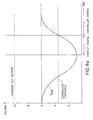
- the pulsed signal will cycle 27 the charging switch 8 off and on thereby applying a pulsed charging current to the battery, as shown in figure 4a.
- the start up charge is obtained up to the threshold value in less time and while wasting less energy than the prior art system.
- the comparator 12 disables the pulse generator 13 and enables the controller 11 which assumes control of the remaining charging requirement.
- FIG. 4a An example of a charging cycle using the start up charger of this invention is shown in the graph of figure 4a.
- the voltages indicated are relative to a 6 volt system and for illustration only as they will vary considerably depending on the specifications for the cellular phone and the associated battery pack.
- a typical voltage profile for the start up capacitor 14 is shown in figure 4b related to the pulsed actuation of charger 9 shown in figure 4a.
Landscapes
- Engineering & Computer Science (AREA)
- Power Engineering (AREA)
- Charge And Discharge Circuits For Batteries Or The Like (AREA)
- Secondary Cells (AREA)
Abstract
Description
Claims (9)
- A battery charging system for a cellular phone, said cellular phone having a controller constructed to operate the battery charging system when enabled, said controller having a predetermined minimum operating voltage threshold, said charging system comprising:a charger for connection to the cellular phone to provide a charging current to the battery when the battery is depleted;a charger switch connected to the charger and to the controller to actuate the charger in response to a signal from the controller when the voltage of the battery falls to an undesirable level;a comparator connected to sense battery voltage and compare said voltage to said voltage threshold and to enable said controller when said battery voltage is equal to or in excess of said voltage threshold; anda start up charger module comprising a pulse generator connected to the charger switch to cycle said switch on and off when said start up charger is enabled, said start up charger connected to said comparator and enabled thereby when said battery voltage is depleted below said threshold value.
- A battery charging system for a cellular phone, said cellular phone having a controller constructed to operate the battery charging system when enabled, said controller having a predetermined minimum operating voltage threshold, said charging system as described in claim 1 wherein the pulse generator is powered by the idle voltage output of the charger.
- A battery charging system for a cellular phone, said cellular phone having a controller constructed to operate the battery charging system when enabled, said controller having a predetermined minimum operating voltage threshold, said charging system as described in claim 2 further comprising a capacitor connected to the charger to receive said idle voltage output and wherein said pulse generator is powered by the output of said capacitor.
- A battery charging system for a cellular phone, said cellular phone having a controller constructed to operate the battery charging system when enabled, said controller having a predetermined minimum operating voltage threshold, said charging system as described in claim 1 wherein said comparator disables said start up charger when the battery voltage reaches said voltage threshold.
- In a battery charging system for a cellular telephone having a charger, a charging switch for actuating said charger, and a controller, a method for replenishing the voltage level of the battery comprising the steps of:connecting the cellular telephone to the charger;sensing the voltage level of the battery and comparing said voltage to a predetermined minimum voltage threshold;enabling the controller when said battery voltage level is at least equal to said voltage threshold, wherein said controller actuates said charger switch to allow the charger to replenish the battery;disabling the controller when said battery voltage is below said voltage threshold;generating a pulsed signal for connection to the charging switch to cycle said switch on and off in response thereto when said battery voltage is below said voltage threshold, said cycling of said switch operating to charge the battery to at least said voltage threshold; anddisabling said pulsed signal when said battery voltage reaches said voltage threshold.
- In a battery charging system for a cellular telephone having a charger, a charging switch for actuating said charger, and a controller, a method for replenishing the voltage level of the battery as described in claim 5 further comprising the step of powering the generation of the pulsed signal by connection to the output of the charger.
- In a battery charging system for a cellular telephone having a charger, a charging switch for actuating said charger, and a controller, a method for replenishing the voltage level of the battery as described in claim 6 wherein the step of powering the pulsed signal comprises charging a capacitor by connection to the output of the charger and using the discharge of said capacitor to power said pulse generation.
- A battery powered device comprising a controller, a battery charging circuit, a pulse generator and a battery voltage comparator, wherein above a predetermined battery voltage threshold the controller is operable to enable the charging circuit whilst below the threshold the charging circuit is cyclically enabled in accordance with the output of the pulse generator.
- A device as claimed in Claim 8, wherein the charging circuit is enabled by the controller in accordance with a pre-determined algorithm.
Applications Claiming Priority (2)
| Application Number | Priority Date | Filing Date | Title |
|---|---|---|---|
| US09/330,479 US6157172A (en) | 1999-06-11 | 1999-06-11 | Charging method and device |
| US330479 | 1999-06-11 |
Publications (2)
| Publication Number | Publication Date |
|---|---|
| EP1059721A2 true EP1059721A2 (en) | 2000-12-13 |
| EP1059721A3 EP1059721A3 (en) | 2001-08-08 |
Family
ID=23289965
Family Applications (1)
| Application Number | Title | Priority Date | Filing Date |
|---|---|---|---|
| EP00304929A Withdrawn EP1059721A3 (en) | 1999-06-11 | 2000-06-09 | Improved charging method and device |
Country Status (2)
| Country | Link |
|---|---|
| US (2) | US6157172A (en) |
| EP (1) | EP1059721A3 (en) |
Families Citing this family (10)
| Publication number | Priority date | Publication date | Assignee | Title |
|---|---|---|---|---|
| US20040120088A1 (en) * | 2002-12-24 | 2004-06-24 | Zone Technology Inc. | Intelligent electronic device protection circuit |
| KR100402916B1 (en) * | 2003-05-17 | 2003-10-22 | Byong Seop Yoo | Cellular phone charger and method for controlling the same |
| JP3928643B2 (en) * | 2005-01-26 | 2007-06-13 | ブラザー工業株式会社 | Telephone |
| US20070090845A1 (en) * | 2005-10-14 | 2007-04-26 | Honeywell International, Inc. | Method and apparatus for battery testing using a single microprocessor port |
| EP1964234B1 (en) * | 2005-12-15 | 2016-11-16 | Nxp B.V. | Battery recharge prevention principle for short battery voltage dips |
| US8035354B2 (en) * | 2005-12-16 | 2011-10-11 | St-Ericsson Sa | Battery full-charge detection for charge-and-play circuits |
| JP4584197B2 (en) * | 2006-06-30 | 2010-11-17 | 富士通株式会社 | Information access system, active contactless information storage device, and method of accessing information in contactless information storage device |
| US8138724B2 (en) | 2007-06-20 | 2012-03-20 | Intel Corporation | Battery pulse charging method and apparatus |
| US9436479B2 (en) | 2011-01-17 | 2016-09-06 | Qualcomm Incorporated | Booting a mobile electronic device with a low battery based on a dynamic boot threshold |
| KR101844287B1 (en) * | 2012-02-03 | 2018-04-02 | 삼성전자 주식회사 | Method and apparatus for charging battery |
Family Cites Families (7)
| Publication number | Priority date | Publication date | Assignee | Title |
|---|---|---|---|---|
| FI109567B (en) * | 1991-02-25 | 2002-08-30 | Nokia Corp | Quick charging device |
| US5442274A (en) * | 1992-08-27 | 1995-08-15 | Sanyo Electric Company, Ltd. | Rechargeable battery charging method |
| FI96465C (en) * | 1994-05-16 | 1996-06-25 | Nokia Mobile Phones Ltd | A method and coupling arrangement for identifying a rechargeable battery charger to a portable device |
| FI99176C (en) * | 1994-11-11 | 1997-10-10 | Nokia Mobile Phones Ltd | Procedure for fast charging of different types of batteries |
| FI112730B (en) * | 1995-09-05 | 2003-12-31 | Nokia Corp | Determination of the accumulator voltage between the charge and the charging device for accumulators |
| DE19609140A1 (en) * | 1996-03-08 | 1997-09-18 | Nokia Mobile Phones Ltd | Charging circuit |
| EP0847123B1 (en) * | 1996-05-21 | 2004-12-29 | Matsushita Electric Industrial Co., Ltd. | Pulse charging method and a charger |
-
1999
- 1999-06-11 US US09/330,479 patent/US6157172A/en not_active Expired - Fee Related
-
2000
- 2000-01-12 US US09/481,962 patent/US6169388B1/en not_active Expired - Fee Related
- 2000-06-09 EP EP00304929A patent/EP1059721A3/en not_active Withdrawn
Also Published As
| Publication number | Publication date |
|---|---|
| US6169388B1 (en) | 2001-01-02 |
| US6157172A (en) | 2000-12-05 |
| EP1059721A3 (en) | 2001-08-08 |
Similar Documents
| Publication | Publication Date | Title |
|---|---|---|
| US6462507B2 (en) | Apparatus and method for initial charging, self-starting, and operation of a power supply with an intermittent and/or variable energy source and a rechargeable energy storage device | |
| KR100391005B1 (en) | Battery having a built-in controller | |
| EP2736146A1 (en) | Vehicle power unit | |
| JP2015015896A (en) | Apparatus for implementing unregulated dormant mode in power converter | |
| US11285822B2 (en) | Electric power system and control method therefor | |
| US6246890B1 (en) | Portable telephone with built-in charger | |
| US6169388B1 (en) | Charging method and device | |
| KR20020003377A (en) | System and method for maintenance charging of battery cells | |
| JP2001521851A (en) | Method and circuit for controlling charging of a dual battery electrical system | |
| JP2013048552A (en) | Lithium iron phosphate ultra fast battery charger | |
| KR20180101756A (en) | Appratus and method for wake-up sleep mode mcu | |
| US6326769B1 (en) | Limitation of power dissipation in Li battery | |
| KR20200042136A (en) | Automobile Battery Emergency Charging Device and Method | |
| JP2010041826A (en) | Ac-dc converter and electronic apparatus using the same | |
| US11594954B2 (en) | Soft start method for a single inductor multiple output power supply | |
| JP2004147409A (en) | Power supply | |
| JP4067554B2 (en) | Power storage device | |
| KR20030020933A (en) | Battery pack discharge recovery circuit | |
| CN113794263A (en) | Photovoltaic power supply circuit, control method, electrical equipment and electric energy scheduling method | |
| JP5350734B2 (en) | Secondary battery discharge circuit, secondary battery discharge method and information processing apparatus | |
| KR20090114842A (en) | Supercap initial charging device for fuel cell hybrid vehicle | |
| TWI868234B (en) | Battery charging method, battery charger device and battery charger system | |
| JPH11262197A (en) | Charging unit | |
| JP3810562B2 (en) | Legged mobile robot | |
| KR100507496B1 (en) | Precharge current and discharge current control apparatus of electric vehicle |
Legal Events
| Date | Code | Title | Description |
|---|---|---|---|
| PUAI | Public reference made under article 153(3) epc to a published international application that has entered the european phase |
Free format text: ORIGINAL CODE: 0009012 |
|
| AK | Designated contracting states |
Kind code of ref document: A2 Designated state(s): DE FR GB IT |
|
| AX | Request for extension of the european patent |
Free format text: AL;LT;LV;MK;RO;SI |
|
| PUAL | Search report despatched |
Free format text: ORIGINAL CODE: 0009013 |
|
| AK | Designated contracting states |
Kind code of ref document: A3 Designated state(s): AT BE CH CY DE DK ES FI FR GB GR IE IT LI LU MC NL PT SE |
|
| AX | Request for extension of the european patent |
Free format text: AL;LT;LV;MK;RO;SI |
|
| RIC1 | Information provided on ipc code assigned before grant |
Free format text: 7H 02J 7/00 A, 7H 02J 7/04 B |
|
| 17P | Request for examination filed |
Effective date: 20011207 |
|
| RAP1 | Party data changed (applicant data changed or rights of an application transferred) |
Owner name: NOKIA CORPORATION |
|
| AKX | Designation fees paid |
Free format text: DE FR GB IT |
|
| STAA | Information on the status of an ep patent application or granted ep patent |
Free format text: STATUS: THE APPLICATION HAS BEEN WITHDRAWN |
|
| 18W | Application withdrawn |
Effective date: 20021125 |