EP1059679A2 - Storage battery - Google Patents
Storage battery Download PDFInfo
- Publication number
- EP1059679A2 EP1059679A2 EP00304764A EP00304764A EP1059679A2 EP 1059679 A2 EP1059679 A2 EP 1059679A2 EP 00304764 A EP00304764 A EP 00304764A EP 00304764 A EP00304764 A EP 00304764A EP 1059679 A2 EP1059679 A2 EP 1059679A2
- Authority
- EP
- European Patent Office
- Prior art keywords
- monoblock
- container
- cell
- storage battery
- containers
- Prior art date
- Legal status (The legal status is an assumption and is not a legal conclusion. Google has not performed a legal analysis and makes no representation as to the accuracy of the status listed.)
- Withdrawn
Links
Images





Classifications
-
- H—ELECTRICITY
- H01—ELECTRIC ELEMENTS
- H01M—PROCESSES OR MEANS, e.g. BATTERIES, FOR THE DIRECT CONVERSION OF CHEMICAL ENERGY INTO ELECTRICAL ENERGY
- H01M50/00—Constructional details or processes of manufacture of the non-active parts of electrochemical cells other than fuel cells, e.g. hybrid cells
- H01M50/20—Mountings; Secondary casings or frames; Racks, modules or packs; Suspension devices; Shock absorbers; Transport or carrying devices; Holders
- H01M50/258—Modular batteries; Casings provided with means for assembling
- H01M50/26—Assemblies sealed to each other in a non-detachable manner
-
- H—ELECTRICITY
- H01—ELECTRIC ELEMENTS
- H01M—PROCESSES OR MEANS, e.g. BATTERIES, FOR THE DIRECT CONVERSION OF CHEMICAL ENERGY INTO ELECTRICAL ENERGY
- H01M50/00—Constructional details or processes of manufacture of the non-active parts of electrochemical cells other than fuel cells, e.g. hybrid cells
- H01M50/10—Primary casings; Jackets or wrappings
- H01M50/147—Lids or covers
-
- Y—GENERAL TAGGING OF NEW TECHNOLOGICAL DEVELOPMENTS; GENERAL TAGGING OF CROSS-SECTIONAL TECHNOLOGIES SPANNING OVER SEVERAL SECTIONS OF THE IPC; TECHNICAL SUBJECTS COVERED BY FORMER USPC CROSS-REFERENCE ART COLLECTIONS [XRACs] AND DIGESTS
- Y02—TECHNOLOGIES OR APPLICATIONS FOR MITIGATION OR ADAPTATION AGAINST CLIMATE CHANGE
- Y02E—REDUCTION OF GREENHOUSE GAS [GHG] EMISSIONS, RELATED TO ENERGY GENERATION, TRANSMISSION OR DISTRIBUTION
- Y02E60/00—Enabling technologies; Technologies with a potential or indirect contribution to GHG emissions mitigation
- Y02E60/10—Energy storage using batteries
-
- Y—GENERAL TAGGING OF NEW TECHNOLOGICAL DEVELOPMENTS; GENERAL TAGGING OF CROSS-SECTIONAL TECHNOLOGIES SPANNING OVER SEVERAL SECTIONS OF THE IPC; TECHNICAL SUBJECTS COVERED BY FORMER USPC CROSS-REFERENCE ART COLLECTIONS [XRACs] AND DIGESTS
- Y02—TECHNOLOGIES OR APPLICATIONS FOR MITIGATION OR ADAPTATION AGAINST CLIMATE CHANGE
- Y02P—CLIMATE CHANGE MITIGATION TECHNOLOGIES IN THE PRODUCTION OR PROCESSING OF GOODS
- Y02P70/00—Climate change mitigation technologies in the production process for final industrial or consumer products
- Y02P70/50—Manufacturing or production processes characterised by the final manufactured product
Definitions
- the present invention relates to a high output storage battery, such as a lead-acid storage battery formed by uniting storage batteries having a plurality of cells.
- the connections between the cells are made over the cell container side walls.
- the intercell connectors that electrically connect the cells are sealed by adhesive in recesses provided on the inside surface of the container cover.
- the adhesive is also used to bond the cell containers and the container cover.
- the recesses and the fitting grooves are complicated, and it is very difficult to fill the adhesive in the recesses and grooves uniformly.
- the cell containers are arranged in a row, it does not present so serious problems.
- the problem is when cell containers are arranged in a plurality of rows.
- some cell containers are surrounded on all the four sides by the adjacent cell containers. In such a case, it is quite difficult to fit the container cover into the cell containers. That has been a problem in the manufacturing process.
- Such deformation of the cell container can cause extreme concentration of stress in the bonded portion between the cell container and the container cover, resulting in the separation of the bonded portion and affecting the liquid tightness and air tightness between the container and the container cover, thus greatly deteriorating the performance of the storage battery.
- the present invention provides a storage battery which comprises a plurality of monoblock containers put together with some space provided between them and a common container cover to close the openings of the monoblock containers, each monoblock container having a plurality of cell compartments separated from each other by partitions and each cell compartment housing an assembly element including positive and negative electrode plates stacked with separators placed between them.
- the assembly element in each cell compartment of the monoblock container is electrically connected in series with the assembly element in the next cell compartment through the aperture provided in the partition between the cell compartments.
- a pair of output terminals - the positive electrode pole and the negative electrode pole are provided at the ends of a block of assembly elements connected to each other.
- each monoblock container has two parallel cell rows of cell compartments, the cell compartments separated from each other by partition.
- Each cell row is formed of cell compartments arranged in one direction.
- the two cell rows of cell compartments are provided side by side in parallel.
- the respective monoblock containers are so positioned that the cell rows are in parallel with each other.
- the assembly elements of the respective cell rows in the monoblock container are electrically connected in series through apertures - an aperture provided in the partition between the assembly elements in the adjacent cell compartments.
- the assembly element in the last cell compartment of the first cell row is connected in series to the assembly element in the cell compartment in the adjacent and corresponding position on the second cell row, also through an aperture provided in the partition between the two cell rows.
- the assembly element in the first cell compartment at the first end of one cell row has one positive electrode pole and the assembly element in the corresponding cell compartment on the other cell row has one negative electrode pole.
- the pair of the electrode poles permits the taking out of the output of the cells in the monoblock container.
- the container cover has a positive terminal connected to the positive electrode pole of the monoblock container at one end, a negative electrode terminal connected to the negative electrode pole of the monoblock container at the other end, and connectors that connect the positive electrode poles and the negative electrode poles of the neighboring monoblock containers.
- each monoblock container has one cell row including a plurality of cell compartments disposed in one direction and separated from each other by partitions.
- the respective monoblock containers are so arranged that the cell rows are in parallel with each other.
- the assembly element of each cell compartment of the monoblock container is electrically connected to the assembly element of the neighboring cell compartment through an aperture provided in the partition between them.
- the assembly element in the cell compartment at one end has a positive electrode pole while the assembly element in the cell compartment at the other end has a negative electrode pole.
- the container cover has a positive terminal connected to the positive electrode pole of the monoblock container at one end, a negative electrode terminal connected to the negative electrode pole of the monoblock container at the other end, and connectors that connect the positive electrode poles and the negative electrode poles of the neighboring monoblock containers.
- the two ends of the connector are each connected to metal bushings insert molded to the container cover.
- One bushing is connected to the positive electrode pole of the monoblock container, while the other bushing is connected to the negative electrode pole of the neighboring monoblock container.
- the stacking direction of the electrode plates of the assembly element is the same as the disposing direction of the cell rows.
- the stacking direction of electrode plates of the assembly element is identical with the disposing direction of the cell compartments.
- the monoblock container has a plurality of parallel ribs on the outside surface which form spaces between that monoblock container and the adjacent monoblock container. The spaces are for coolant to pass through.
- the monoblock container has a plurality of parallel ribs on the outside surface along the lines corresponding to the side ends of the aforesaid partitions, the parallel ribs forming spaces between that monoblock container and the adjacent monoblock container. The spaces are for coolant to pass through.
- the monoblock container has projections at the lower right and left corners of the side face corresponding to the ends of the cell rows.
- One projection is linked with the projection of the adjacent monoblock container via a coupler having holes that fit over the projection.
- the adjacent monoblock containers are united.
- the monoblock container has the ribs pressed against the corresponding ribs of the adjacent monoblock container.
- the adjacent monoblock containers are united with each other via the ribs.
- the monoblock container has a sealed chamber provided with openings communicating with the respective cell compartments, safety valves closing the respective openings in the sealed chamber, and an air passage having an explosion-proof mechanism through which the sealed chamber communicates with the outside.
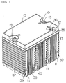
- FIG. 1 to FIG. 6 shows a lead-acid battery in a first embodiment.
- a sealed lead-acid storage battery indicated by the numeral 10 has three monoblock containers 11 disposed side by side and sealed with a common container cover 12, each monoblock container 11 including 6 cells connected to each other in series.
- the container cover 12 has a pair of terminals - a positive electrode terminal 13 and a negative electrode terminal 14.
- the container cover 12 is overlaid with a top plate 15.
- the monoblock containers, container cover and top plate are all made of polypropylene.
- the monoblock container 11 has two cell rows 21, and 22 disposed in parallel with each other as shown in FIGS. 4 and 5.
- the cell row 21 has three cell compartments 21a, 21b and 21c that are placed one after another in a straight line.
- the cell row 22 has three cell compartments 22a, 22b and 22c that are provided also linearly one after another.
- the cell compartments in one cell row are separated by partitions 23, and the cell compartments in one cell row are separated from the cell compartments in another cell row by partition 24.
- Those 6 cell compartments each house an assembly element 25.
- the assembly element 25 is comprised of a number of positive and negative electrode plates piled or stacked one after another with separators between the plates.
- Each assembly element 25 has a strap 26 connected to the lugs of the positive electrode plates and a strap 27 connected to the lugs of the negative electrode plates. At the ends of those straps, there are provided connector pieces 28 which are extended upward to be connected to the adjacent assembly element.
- the adjacent assembly elements in a cell row are connected in the following way.
- the strap on the positive electrode side of one assembly element is connected to the strap on the negative electrode side of the other assembly element through an aperture provided in the partition 23.
- the assembly elements at the adjacent ends of the two cell rows are connected to each other with the straps on the positive and negative electrode sides joined with each other through an aperture provided in the partition 24.
- the assembly elements in the 6 cell compartments are connected in series, forming a block of assembly elements.
- the assembly element at one end of the cell row has a positive electrode pole 29 and the assembly element at the same side end of another cell row has a negative electrode pole 30.
- the output of the block of the assembly elements in the monoblock container 11 can be taken out from the positive electrode pole 29 and the negative electrode pole 30.
- the container cover 12 has connecting means to connect in series the assembly element blocks of each monoblock container. That is, the container cover 12 has 6 lead alloy bushings to connect the electrode poles. And the positive electrode pole 29 and the negative electrode pole 30, both made of lead alloy, in the container 11a shown in FIG. 4 are fit into bushings 31a and 32a on the container cover and joined to the bushings by heating with a burner. Similarly, the positive electrode pole and the negative electrode pole in the container 11b are joined to bushings 31b and 32b. And the positive electrode pole and negative electrode pole in the container 11c are joined to the bushings 31c and 32c.
- the container cover 12 has a connector 33b that connects the bushings 32a and 31b and a connector 33d that connects the bushing 32c and the negative electrode terminal 14 as shown in FIG. 3. While not shown, there are provided a connector for connecting the positive electrode terminal 13 and the bushing 31a and a connector for connecting the bushings 32b and 31c. Those connectors connect in series the assembly element blocks in the containers 11.
- the container cover 12 has ribs 16 to be mated with the opening end of each monoblock container 11 and partitions 17 to be joined with the partitions 23 and 24 of the monoblock container 11.
- the containers and the container cover are united by way of those parts by thermal welding, so that each cell compartment is isolated air-tight and liquid-tight.
- This rib is welded to the corresponding rib (not shown) provided on the top plate 15 by ultrasonic welding.
- a sealed chamber 19 partitioned by the ribs.
- This sealed chamber 19 is provided with pipes that have holes communicating with the respective cell compartments.
- the pipes 20 are sealed with rubber valves 34. A slight space or gap is provided between the top of the rubber valve and the top plate 15.
- the top plate keeps the rubber valves from coming off the pipes.
- the sealed chamber 19 communicates with the outside through an exhaust duct 35 having a flame arrester filter 36 set on the top plate. If the gas pressure rises abnormally in the cell compartment as when gas generates during charging, for example, the gas pushes and expands the rubber valve 34 and enters the sealed chamber 19 and goes out from exhaust duct 35 through the flame arrester filter 36.
- the flame arrester filter 36 prevents the gases generated in the battery from catching fire.
- the monoblock container 11 has a plurality of ribs 37 on the side walls parallel with the cell row that extend horizontally. And when the monoblock containers 11 put together in parallel with each other, the ribs 37 are pressed against with each other, forming air passages between upper and down ribs that cool the containers.
- the monoblock container 11 is provided with a plurality of reinforcing ribs 38 that extend vertically.
- the ribs 37 and 38 provided on the sides of the monoblock container 11 are omitted.
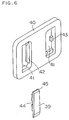
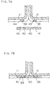
- the projection 39 has a brim 45 at the top so that the top portion is slightly wide and is provided with a recession or an aperture in the middle. Meanwhile, the holes 41 and 41 of the coupler 40 are provided with projected pieces 42 and 43. If, therefore, the projections 39 and 39 of the adjacent containers are pressed into the holes 41 and 41 of the coupler 40, the projected pieces 42 and 43 engage with the brim 45 and the aperture 44 of the projection 39 as shown in FIG. 7, uniting the two adjacent monoblock containers. This way, three monoblock containers are united with four couplers 40 put in place at the lower corners.
- the lead-acid storage battery is fabricated in the following way.
- the assembly elements are placed in the respective cell compartments of the monoblock container 11 and the assembly elements are connected to each other in series. That makes a U-shaped block of assembly elements.
- the first assembly element at the first end of the U-shaped block of assembly elements is connected to the positive electrode pole and the last assembly element at the other end of the block is connected to the negative electrode pole.
- Three monoblock containers 11 are put together in parallel and each two adjacent containers are united with couplers 40.
- the openings of the three monoblock containers 11 are sealed with one container cover 12. The sealing is effected by thermal welding.
- the positive electrode pole and negative electrode pole are welded to the respective bushings of the container cover.
- the welding is done by heating the electrode poles and bushings with burner flame. After that, electrolyte is injected into the cell compartments through the pipes 20. After the assembly elements are well impregnated with electrolyte, the rubber valves 34 are put on the pipes 20. Then, the top plate 15 is placed over the container cover 12, and the two are joined by ultrasonic welding. Thereafter, the assembly elements are energized for formation.
- FIG. 8 is a top view of a lead-acid storage battery with the top plate removed in this embodiment.
- the numeral 12A indicates the container cover. This cover seals the openings of the three monoblock containers 11a, 11b and 11c that have been described in Embodiment 1.
- the cover 12A has the positive electrode pole 29 and the negative electrode pole 30 in each monoblock container passed through it.
- the positive electrode pole 29a of the monoblock container 11a is connected to the positive electrode terminal 13A via connector 33A
- the negative electrode pole 30a is connected to the positive electrode pole 29b of the adjacent monoblock container 11b via connector 33b.
- the negative electrode pole 30b of the monoblock container 11b is connected to the positive electrode pole 29c of the monoblock container 11c via connector 33C.
- the negative electrode pole 30c of the monoblock container 11c is connected to the negative electrode terminal 14A via connector 33D.
- the assembly elements blocks of each monoblock container are connected in series so that the output can be taken from the positive electrode terminal 13A and negative electrode terminal 14A
- the container cover 20A is provided with pipes 20A having openings that communicate with the respective cell compartments. Those pipes are mounted with rubber valves.
- lead wires 51, 52, 53 and 54 for detection of voltage, respectively.
- Those lead wires and lead wire 56 of a thermistor 55 mounted near the positive electrode pole 29b are each connected to connectors 57 that are provided with the respective terminals.
- That configuration permits measurement through lead wires 51 and 52 of the voltage of the block of assembly elements connected in series in the monoblock container 11a. This way, the voltage of the block of assembly elements connected in series in each container can be measured independently by means of lead wires 51 to 54. Also, the temperature of the assembly element in the middle container can be measured by thermistor 55. For efficient measurement of the heat generated by the assembly element, it is desirable to mount the thermistor 55 near, preferably in contact with the electrode pole. As shown, the storage battery of the present embodiment is so configured that the voltage of the battery and the temperature signals can be taken up from the connector 56 in a lump.
- the connector 33, lead wires 51 to 54 and thermistor 55 are mounted in a part separated by partition 18A from the area where the pipes 20A that constitute safety valves are located and that the connector 33, the lead wires 51 to 54 and the thermistor 55 are fixed with an adhesive. While not shown, a top plate is overlaid over the container cover 12A.
- a storage battery to produce a high voltage that is fabricated by uniting a number of monoblock containers generates much heat. Dissipation of that heat is different from container to container. Assembly elements in the containers that fail to dissipate heat well tend to overcharge or overdischarge in a cycle of charge and discharge, impairing the battery characteristics. To prevent such a problem, it is necessary to monitor the condition of assembly elements in the respective containers.
- the lead wires for detection of voltage that are connected to the positive electrode pole or negative electrode pole of each monoblock container are concentrated in one connector 57. That precludes no possibility of misconnection when the lead wires are connected to a voltage monitor. Furthermore, the thermistor is mounted on the middle monoblock container that can not dissipate heat well. That permits proper monitoring of the battery temperature.
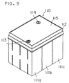
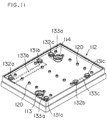
- FIGS. 9 to 13 show a lead-acid storage battery in a third embodiment.
- the lead-acid storage battery indicated by the numeral 110 is composed of three monoblock containers 111a, 111b and 111c arranged so that the cell rows are parallel with each other as in the preceding examples.
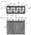
- each monoblock container 111 has a cell row of 6 cell compartments 121a, 121b, 121c, 121d, 121e and 121f separated from each other by partitions 123 and arrayed in one direction.
- the assembly element 125 housed in each cell compartment has a strap 126 connected to the lugs of the positive electrode plates and a strap 127 connected to the lugs of the negative electrode plates.
- the adjacent assembly elements are connected to each other with the strap 126 and the strap 127 connected by a connector piece 128 through an aperture provided in the partition. This way, the assembly elements in the respective cell compartments are connected in series to form a block of assembly elements.
- the assembly element in the first cell compartment of the block of assembly elements has a positive electrode pole 129 and the assembly element in the last cell compartment has a negative electrode pole 130.
- Each monoblock container 111 has vertical ribs 137 on its side walls. Those ribs are provided on the line corresponding to the side ends of every other partition.
- the ribs 137 have a notch 137' in the middle. If the monoblock containers of such a construction are put together, ribbed side to ribbed side, the ribs are pressed against the corresponding ribs of the other container.
- the ribs 137 are provided with notches 137' which form spaces for coolant to pass through. Through this spaces, the heat generated in the storage battery can be dissipated.
- the three neighboring monoblock containers are united to each other by thermally welding the ribs 137 as shown in FIG. 10.
- the container cover 112 has a bushing 131a to connect to the positive electrode pole 129 of the container 111a, a positive electrode terminal 113 connected to the bushing by a connector 133a, a bushing 132a to connect to the negative electrode pole 130 of the container 111a, a bushing 131b to connect to the positive electrode pole of the container 111b and a connector 133b to link bushings 132a and 131b.
- the container cover 112 has bushings 132b and 131c, and a connector 133c to link the two bushings, and bushing 132c, negative electrode terminal 114 and a connector 133d to link the bushing 132c and the negative electrode terminal 114.
- the blocks of assembly elements connected to each other in series in containers 111a, 111b and 111c are connected to each other in series, and the output can be out taken from the positive electrode terminal 113 and negative electrode terminal 114.
- the container cover 112 has pipes 120 having openings that communicate with the cell compartments as in Embodiment 1. Sealed with rubber valves, those pipes serve as safety devices.
- the container cover 112 has a top plate 115 bonded on the top. On the top plate are exposed a positive electrode terminal and a negative electrode terminal.
- the lead alloy bushings and connectors are joined to the container cover by insert molding.
- the bushings may be insert molded to the container cover.
- the connector that connects the bushings may be placed in a recess provided on the container cover, and the recess may be sealed with an adhesive.
- FIG. 14 shows the lead-acid storage battery 110 thus fabricated.
- the battery 110 is installed in a state that the monoblock containers are placed one upon another. The arrangements inside the monoblock containers are also shown.
- the bottom container 111a is placed with its lower side ribs 137 on the installation ground 146 and with its upper side ribs 137 bearing the load of the upper containers.
- the ribs 137 are provided along the line on the outside surfaces that correspond to the side ends of the partitions 123, and can withstand the load. That is, the ribs 137 prevent cracks on the container sides or a deformation of the assembly elements inside the container. In order to enable the container to withstand a greater load, it is an idea to provide a rib along the line corresponding to the side end of each partition.
- the load of the battery 110 is borne on the horizontal underside and there is no fear of container walls getting cracked, either.
- the stacking direction of electrode plates is vertical, and the load increases the stacking pressure, resulting in a longer cycle life.
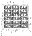
- FIG. 15 shows a comparative example, that is, a 36-volt, 17 Ah lead-acid storage battery 60 composed of 18 monoblock containers, each having one cell.
- the monoblock container 61 is the size of one cell compartment in the monoblock container according to the present invention.
- Each container has ribs 62 and 63 that form spaces between that container and the adjacent container. The two adjacent containers are bonded to each other via those ribs.
- the container houses an assembly element 64 having a strap 65 connected to the positive electrode plates and a strap 66 connected to the negative electrode plates.
- the straps 65 and 66 have connection tabs 67 and 68 that project above the openings of the containers.
- connection tabs 67 and 68 are connected to each other via a lead alloy connection bar 69 placed over the adjacent container side walls facing each other. This way, the adjacent cells are connected in series.
- the negative electrode pole 71 of the lowest block 61a made up of 6 cells and the positive electrode pole 70 of the second block 61b made up of 6 cells are connected to each other by connection bar 72a.
- the negative electrode pole 71 of the second block 61b and the positive electrode pole 70 of the top block 61c are connected to each other by connection bar 72b.
- connection bar 72b This way, the six-cell blocks are connected in series.
- the container cover to seal those containers has recesses for connection bars 69, 72a and 72b placed over the adjacent side walls and grooves to fit into the openings of the containers. Those recesses and grooves are filled with adhesive to bond the containers and the cover and to seal the connection bars.
- the numeral 73 indicates the battery installation ground.
- the lower containers In the storage battery of that construction, the lower containers easily deform and crack especially along the ribs 62 under the load of the upper containers. The deformation of the containers could deform the assembly elements. It is also noted that in case the battery is placed with the side indicated by dotted line 73' on the installation ground, the containers in lower layers deform along the ribs 63. If the container cracks, the electrolyte will be lost. It is also feared that if the assembly elements come under the load, resulting in deformation of the electrode plates, then internal short circuit may be caused. That could shorten the battery life.
- the cells between the containers are all connected in series. That is not restrictive. Those cells may be connected in parallel.
Landscapes
- Chemical & Material Sciences (AREA)
- Chemical Kinetics & Catalysis (AREA)
- Electrochemistry (AREA)
- General Chemical & Material Sciences (AREA)
- Connection Of Batteries Or Terminals (AREA)
- Battery Mounting, Suspending (AREA)
- Sealing Battery Cases Or Jackets (AREA)
Abstract
Description
Claims (19)
- A storage battery comprising a plurality of monoblock containers put together with space provided between adjacent containers and one container cover to seal the openings of said monoblock containers, each of said monoblock containers having a plurality of cell compartments separated from each other by partitions and each of said cell compartments housing an assembly element comprising a plurality of positive electrode plates and negative electrode plates stacked with separators placed between the plates.
- The storage battery in accordance with claim 1,
wherein the assembly element in each of said cell compartments is electrically connected in series with the assembly element in the next adjacent cell compartment through an aperture provided in the partition between the two cell compartments. - The storage battery in accordance with claim 1,
wherein each monoblock container has two cell rows adjacent and parallel to each other, each cell row including a plurality of cell compartments lined up in one direction and separated from each other by partitions, and said monoblock containers being so arranged that said cell rows are parallel with each other. - The storage battery in accordance with claim 1,
wherein each monoblock container has one cell row including a plurality of cell compartments lined up in one direction and separated from each other by partitions, and said monoblock containers being so arranged that said cell rows are parallel with each other. - The storage battery in accordance with claim 3,
wherein each of said monoblock containers has a positive electrode pole connected to the assembly element in the cell compartment at the first end of one cell row and a negative electrode pole connected to the assembly element in the cell compartment in the adjacent and corresponding position of the other cell row, wherein said container cover has a positive electrode terminal connected to the positive electrode pole of the monoblock container at one end, a negative electrode terminal connected to the negative electrode pole of the monoblock container at the other end, and connectors connecting the positive electrode pole and negative electrode pole in the adjacent monoblock containers, and wherein the assembly element in each of said cell rows is electrically connected in series with the assembly element in the next adjacent cell compartment through an aperture provided in the partition between the two cell compartments and wherein the assembly elements in the cell compartments having no positive electrode pole or negative electrode pole are electrically connected in series through an aperture provided in the partition between the two cell rows. - The storage battery in accordance with claim 4,
wherein each of said monoblock containers has a positive electrode pole connected to the assembly element in the cell compartment at the first end and a negative electrode pole connected to the assembly element in the cell compartment at the other end in the same container, wherein said container cover has a positive electrode terminal connected to the positive electrode pole of the monoblock container at one end, a negative electrode terminal connected to the negative electrode pole of the monoblock container at the other end, and connectors connecting the positive electrode pole and negative electrode pole in the adjacent monoblock containers, and wherein the assembly element in each cell row is electrically connected in series with the assembly element in the next adjacent cell compartment through an aperture provided in the partition between the two cell compartments. - The storage battery in accordance with claim 5,
wherein said connector has two ends connected to metal bushings insert molded to said container cover, one end of said bushings being joined to the positive electrode pole of one monoblock container and the other end being joined to the negative electrode pole of the adjacent monoblock container. - The storage battery in accordance with claim 6,
wherein said connector has two ends connected to metal bushings insert molded to said container cover, one end of said bushings being joined to the positive electrode pole of one monoblock container and the other end being joined to the negative electrode pole of the adjacent monoblock container. - The storage battery in accordance with claim 3,
wherein the stacking direction of electrode plates in each assembly element is the same as the disposing direction of the cell rows. - The storage battery in accordance with claim 4,
wherein the stacking direction of electrode plates in each assembly element is the same as the disposing direction of the cell compartment of the respective cell rows. - The storage battery in accordance with claim 1,
wherein each of said monoblock containers has a plurality of parallel ribs on its outside that form spaces for coolant to pass through between that monoblock container and the adjacent monoblock container. - The storage battery in accordance with claim 4,
wherein each of said monoblock containers has parallel ribs that form spaces for coolant to pass through between that monoblock container and the adjacent monoblock container, said ribs being provided along the line on the outside surfaces that correspond to the side ends of said partition. - The storage battery in accordance with claim 3,
wherein each of said monoblock containers has projections at the lower right and left corners on the outside surface of the sides facing the ends of the cell rows, one of the projections of the monoblock container and the neighboring projection on the adjacent monoblock container being linked with a coupler with the two projections fit into the holes provided in said coupler, thereby uniting the neighboring monoblock containers together. - The storage battery in accordance with claim 4,
wherein each of said monoblock containers has projections at the lower right and left corners on the outside surface of the sides facing the ends of the cell rows, one of the projections of the monoblock container and the neighboring projection on the adjacent monoblock container being linked with a coupler with the two projections fit into the holes provided in said coupler, thereby uniting the neighboring monoblock containers together. - The storage battery in accordance with claim 11,
wherein the ribs of the monoblock container are pressed against the corresponding ribs of the adjacent monoblock container and the monoblock container is welded to the adjacent monoblock container on those ribs. - The storage battery in accordance with claim 11,
wherein said ribs are lowered or notched in part. - The storage battery in accordance with claim 1,
wherein said container cover has one sealed chamber provided with openings communicating with the respective cell compartments, safety valves closing said openings in said sealed chamber, and an air passage having an explosion-proof mechanism through which said sealed chamber communicates with the outside. - The storage battery in accordance with claim 2, further comprising lead wires for detection of the voltage of series connected assembly elements in each monoblock container, a thermistor for detection of temperature in a cell at least in one monoblock container, a lead wire for said thermistor, and a connector having terminals for said both lead wires, said connector being mounted on the container cover.
- The storage battery in accordance with claim 18,
wherein said thermistor is mounted in contact with an electrode pole.
Applications Claiming Priority (6)
| Application Number | Priority Date | Filing Date | Title |
|---|---|---|---|
| JP15907099 | 1999-06-07 | ||
| JP15907099 | 1999-06-07 | ||
| JP16191099 | 1999-06-09 | ||
| JP16190999 | 1999-06-09 | ||
| JP16191099 | 1999-06-09 | ||
| JP16190999 | 1999-06-09 |
Publications (2)
| Publication Number | Publication Date |
|---|---|
| EP1059679A2 true EP1059679A2 (en) | 2000-12-13 |
| EP1059679A3 EP1059679A3 (en) | 2002-09-11 |
Family
ID=27321463
Family Applications (1)
| Application Number | Title | Priority Date | Filing Date |
|---|---|---|---|
| EP00304764A Withdrawn EP1059679A3 (en) | 1999-06-07 | 2000-06-06 | Storage battery |
Country Status (4)
| Country | Link |
|---|---|
| US (1) | US6635380B1 (en) |
| EP (1) | EP1059679A3 (en) |
| CN (1) | CN1167149C (en) |
| TW (1) | TW447153B (en) |
Cited By (8)
| Publication number | Priority date | Publication date | Assignee | Title |
|---|---|---|---|---|
| WO2002095843A3 (en) * | 2001-05-21 | 2003-02-27 | Ovonic Battery Co | Monoblock battery |
| EP1818998A3 (en) * | 2006-02-02 | 2008-02-06 | Samsung SDI Co., Ltd. | A cell barrier for a rechargeable battery module |
| EP2445032A1 (en) * | 2010-10-19 | 2012-04-25 | SB LiMotive Co., Ltd. | Battery module |
| WO2012107365A1 (en) * | 2011-02-08 | 2012-08-16 | Sb Limotive Company Ltd. | Battery cell module and method for producing the battery cell module |
| EP2515359A1 (en) * | 2011-04-21 | 2012-10-24 | SB LiMotive Co., Ltd. | Cover including gas outlet for a battery module |
| US9553288B2 (en) | 2014-08-20 | 2017-01-24 | Ford Global Technologies, Llc | Step configuration for traction battery housing |
| US9614208B2 (en) | 2011-10-10 | 2017-04-04 | Samsung Sdi Co., Ltd. | Battery pack with degassing cover and plate thereon |
| FR3130457A1 (en) | 2021-12-13 | 2023-06-16 | Powzl | ELECTRIC GENERATOR COMPRISING A PLURALITY OF BATTERIES |
Families Citing this family (36)
| Publication number | Priority date | Publication date | Assignee | Title |
|---|---|---|---|---|
| US6255015B1 (en) * | 1998-08-23 | 2001-07-03 | Ovonic Battery Company, Inc. | Monoblock battery assembly |
| DE10349557B4 (en) * | 2003-10-22 | 2010-09-09 | Infineon Technologies Ag | Use of a capacitor arrangement and method for driving |
| US7547487B1 (en) * | 2004-05-18 | 2009-06-16 | Ovonic Battery Company, Inc. | Multi-cell battery assembly |
| RU2276432C1 (en) * | 2004-09-06 | 2006-05-10 | Открытое акционерное общество "Комсомольский-на-Амуре аккумуляторный завод" | Storage battery |
| USD527344S1 (en) | 2004-11-16 | 2006-08-29 | Teledyne Technologies Incorporated | Battery case |
| DE102006030770A1 (en) * | 2006-06-30 | 2008-01-24 | Jungheinrich Ag | Battery block for a truck |
| KR100920207B1 (en) * | 2006-11-27 | 2009-10-06 | 주식회사 엘지화학 | Power switching module for manufacturing battery module assembly |
| US10014508B2 (en) * | 2006-11-27 | 2018-07-03 | Lg Chem, Ltd. | Battery module assembly |
| KR101552872B1 (en) * | 2008-08-08 | 2015-09-18 | 가부시키가이샤 지에스 유아사 | Lead storage battery |
| US7855011B2 (en) * | 2008-08-28 | 2010-12-21 | International Battery, Inc. | Monoblock lithium ion battery |
| KR101041153B1 (en) * | 2009-03-04 | 2011-06-13 | 에스비리모티브 주식회사 | Secondary Battery and Its Module |
| TWM382596U (en) * | 2009-12-23 | 2010-06-11 | Amita Technologies Inc Co Ltd | Battery module |
| US20110177379A1 (en) * | 2010-03-25 | 2011-07-21 | Ford Global Technologies, Llc | Battery assembly |
| US8323818B2 (en) * | 2010-03-25 | 2012-12-04 | Ford Global Technologies, Llc | Battery cooling |
| US9123944B2 (en) * | 2010-03-25 | 2015-09-01 | Ford Global Technologies, Llc | Battery cover assembly |
| CN101944633B (en) * | 2010-09-29 | 2012-11-07 | 广东正飞移动照明有限公司 | Lithium ion battery and charger using same |
| KR101191660B1 (en) | 2010-11-08 | 2012-10-17 | 에스비리모티브 주식회사 | Battery module |
| JP5772525B2 (en) * | 2011-11-11 | 2015-09-02 | 株式会社オートネットワーク技術研究所 | Battery wiring module |
| US9660231B2 (en) * | 2012-02-03 | 2017-05-23 | Samsung Sdi Co., Ltd. | Battery pack |
| JP5651629B2 (en) * | 2012-03-22 | 2015-01-14 | 株式会社東芝 | battery |
| JP5606480B2 (en) * | 2012-03-22 | 2014-10-15 | 株式会社東芝 | Battery and battery manufacturing method |
| JP6523607B2 (en) * | 2013-04-08 | 2019-06-05 | 株式会社Gsユアサ | Battery module |
| CN104505473B (en) * | 2014-12-18 | 2017-05-10 | 天能电池集团有限公司 | Lead-acid storage battery middle cover and storage battery inner formation process |
| AU2016394097B2 (en) * | 2016-02-26 | 2020-02-20 | Tti (Macao Commercial Offshore) Limited | Battery packs and method of assembling battery packs |
| US10256453B2 (en) * | 2016-07-20 | 2019-04-09 | East Penn Manufacturing Co. | Lead acid battery cell connecting assembly |
| US11588214B2 (en) | 2017-01-27 | 2023-02-21 | Cps Technology Holdings Llc | Battery straps |
| EP3635805B1 (en) | 2017-06-09 | 2023-09-06 | CPS Technology Holdings LLC | Lead-acid battery |
| US11936032B2 (en) | 2017-06-09 | 2024-03-19 | Cps Technology Holdings Llc | Absorbent glass mat battery |
| WO2019023672A1 (en) * | 2017-07-28 | 2019-01-31 | Northstar Battery Company, Llc | Wireless enabled monobloc |
| US10823786B2 (en) | 2017-07-28 | 2020-11-03 | Northstar Battery Company, Llc | Battery with internal monitoring system |
| USD866466S1 (en) * | 2017-10-25 | 2019-11-12 | Kk Wind Solutions A/S | Battery holder |
| CN111902901B (en) * | 2017-12-13 | 2022-04-05 | 凯尊创新有限公司 | Lithium ion battery |
| CN207967135U (en) * | 2018-03-16 | 2018-10-12 | 宁德时代新能源科技股份有限公司 | Battery modules and battery pack |
| KR102734010B1 (en) | 2018-11-21 | 2024-11-25 | 삼성전자주식회사 | Liquid crystal polymer, composite composition, article, battery case, and battery |
| CN113851774B (en) * | 2021-09-28 | 2024-11-26 | 天津雅迪实业有限公司 | Lead-acid battery connecting wire cover plate and electric vehicle |
| US11912123B2 (en) * | 2021-12-08 | 2024-02-27 | Ford Global Technologies, Llc | Traction battery pack venting system and venting method |
Family Cites Families (8)
| Publication number | Priority date | Publication date | Assignee | Title |
|---|---|---|---|---|
| US729550A (en) * | 1898-12-16 | 1903-06-02 | Electric Vehicle Company | Battery-jar. |
| US3338452A (en) * | 1964-11-23 | 1967-08-29 | Michael J Oakley | Case for storage battery cell |
| US4347294A (en) | 1981-02-12 | 1982-08-31 | Santiago Mejia | Novel electric storage battery assembly |
| US4521498A (en) * | 1982-07-22 | 1985-06-04 | Gates Energy Products, Inc. | Through-the-partition intercell connection and method |
| US4592972A (en) * | 1983-07-22 | 1986-06-03 | Gates Energy Products, Inc. | Vibration-resistant battery assembly |
| JPH08227700A (en) | 1995-02-22 | 1996-09-03 | Shin Kobe Electric Mach Co Ltd | Battery case for lead acid battery and lead acid battery using the battery case |
| JP3271495B2 (en) | 1995-10-24 | 2002-04-02 | 松下電器産業株式会社 | Battery pack |
| JP4088359B2 (en) * | 1997-10-20 | 2008-05-21 | 松下電器産業株式会社 | Collective sealed secondary battery |
-
2000
- 2000-06-05 TW TW089110974A patent/TW447153B/en not_active IP Right Cessation
- 2000-06-06 EP EP00304764A patent/EP1059679A3/en not_active Withdrawn
- 2000-06-06 US US09/588,493 patent/US6635380B1/en not_active Expired - Fee Related
- 2000-06-07 CN CNB001183419A patent/CN1167149C/en not_active Expired - Fee Related
Cited By (14)
| Publication number | Priority date | Publication date | Assignee | Title |
|---|---|---|---|---|
| US7264901B2 (en) * | 1998-08-23 | 2007-09-04 | Ovonic Battery Company, Inc. | Monoblock battery |
| WO2002095843A3 (en) * | 2001-05-21 | 2003-02-27 | Ovonic Battery Co | Monoblock battery |
| EP1818998A3 (en) * | 2006-02-02 | 2008-02-06 | Samsung SDI Co., Ltd. | A cell barrier for a rechargeable battery module |
| US9123956B2 (en) | 2006-02-02 | 2015-09-01 | Samsung Sdi Co., Ltd. | Cell barrier for secondary battery module and secondary battery module |
| CN102456857B (en) * | 2010-10-19 | 2014-10-29 | 三星Sdi株式会社 | Battery module |
| US8748021B2 (en) | 2010-10-19 | 2014-06-10 | Samsung Sdi Co., Ltd. | Battery module |
| CN102456857A (en) * | 2010-10-19 | 2012-05-16 | Sb锂摩托有限公司 | Battery module |
| EP2445032A1 (en) * | 2010-10-19 | 2012-04-25 | SB LiMotive Co., Ltd. | Battery module |
| WO2012107365A1 (en) * | 2011-02-08 | 2012-08-16 | Sb Limotive Company Ltd. | Battery cell module and method for producing the battery cell module |
| EP2515359A1 (en) * | 2011-04-21 | 2012-10-24 | SB LiMotive Co., Ltd. | Cover including gas outlet for a battery module |
| US8652666B2 (en) | 2011-04-21 | 2014-02-18 | Samsung Sdi Co., Ltd. | Battery module |
| US9614208B2 (en) | 2011-10-10 | 2017-04-04 | Samsung Sdi Co., Ltd. | Battery pack with degassing cover and plate thereon |
| US9553288B2 (en) | 2014-08-20 | 2017-01-24 | Ford Global Technologies, Llc | Step configuration for traction battery housing |
| FR3130457A1 (en) | 2021-12-13 | 2023-06-16 | Powzl | ELECTRIC GENERATOR COMPRISING A PLURALITY OF BATTERIES |
Also Published As
| Publication number | Publication date |
|---|---|
| CN1276632A (en) | 2000-12-13 |
| TW447153B (en) | 2001-07-21 |
| CN1167149C (en) | 2004-09-15 |
| EP1059679A3 (en) | 2002-09-11 |
| US6635380B1 (en) | 2003-10-21 |
Similar Documents
| Publication | Publication Date | Title |
|---|---|---|
| US6635380B1 (en) | Storage battery having a plurality of containers with one cover | |
| CA1111103A (en) | Battery and battery container having air-flow passages therethrough | |
| EP1619740B1 (en) | Battery pack | |
| US6304057B1 (en) | Structure for fixing electrode plate groups in cells that constitute a battery module | |
| KR20040033030A (en) | A bipolar battery and a biplate assembly | |
| KR101145732B1 (en) | Battery module containing a battery cell assembly having a heat exchanger | |
| US8598884B2 (en) | Car battery system | |
| US6551741B1 (en) | Battery module | |
| JP4568388B2 (en) | Integrated coupling battery with built-in circulating fluid heat exchanger | |
| US10290909B2 (en) | Battery module having temperature sensor | |
| CA1279365C (en) | Electric storage battery | |
| JP5492738B2 (en) | Secondary battery and secondary battery module | |
| US20250112326A1 (en) | Battery pack | |
| WO2018103273A1 (en) | Lead-acid battery and battery pack | |
| EP1164645A1 (en) | Electrical storage cell batteries | |
| WO1999063611A1 (en) | Sealed rechargeable battery plenum stabilized with state changeable substance | |
| JP2022082532A (en) | Metal ion storage battery with degassing duct, related to battery modules or battery packs with liquid cooling | |
| KR100770106B1 (en) | Lithium secondary battery | |
| KR20170095070A (en) | Battery Pack | |
| US20240322322A1 (en) | Battery pack | |
| US20030087149A1 (en) | Battery | |
| WO2024251065A1 (en) | Preparation process for high-capacity battery | |
| JP2001057202A (en) | Storage battery | |
| CN121507254A (en) | Battery cover and battery | |
| US20260018698A1 (en) | Battery pack, energy storage device, and electrical apparatus |
Legal Events
| Date | Code | Title | Description |
|---|---|---|---|
| PUAI | Public reference made under article 153(3) epc to a published international application that has entered the european phase |
Free format text: ORIGINAL CODE: 0009012 |
|
| AK | Designated contracting states |
Kind code of ref document: A2 Designated state(s): AT BE CH CY DE DK ES FI FR GB GR IE IT LI LU MC NL PT SE |
|
| AX | Request for extension of the european patent |
Free format text: AL;LT;LV;MK;RO;SI |
|
| PUAL | Search report despatched |
Free format text: ORIGINAL CODE: 0009013 |
|
| AK | Designated contracting states |
Kind code of ref document: A3 Designated state(s): AT BE CH CY DE DK ES FI FR GB GR IE IT LI LU MC NL PT SE |
|
| AX | Request for extension of the european patent |
Free format text: AL;LT;LV;MK;RO;SI |
|
| 17P | Request for examination filed |
Effective date: 20030120 |
|
| AKX | Designation fees paid |
Designated state(s): DE FR GB IT SE |
|
| 17Q | First examination report despatched |
Effective date: 20070329 |
|
| RAP1 | Party data changed (applicant data changed or rights of an application transferred) |
Owner name: PANASONIC CORPORATION |
|
| STAA | Information on the status of an ep patent application or granted ep patent |
Free format text: STATUS: THE APPLICATION IS DEEMED TO BE WITHDRAWN |
|
| 18D | Application deemed to be withdrawn |
Effective date: 20101231 |