EP1059651A2 - Apparatus and associated method for supporting a vacuum interrupter sub-assembly during manufacture - Google Patents
Apparatus and associated method for supporting a vacuum interrupter sub-assembly during manufacture Download PDFInfo
- Publication number
- EP1059651A2 EP1059651A2 EP00111270A EP00111270A EP1059651A2 EP 1059651 A2 EP1059651 A2 EP 1059651A2 EP 00111270 A EP00111270 A EP 00111270A EP 00111270 A EP00111270 A EP 00111270A EP 1059651 A2 EP1059651 A2 EP 1059651A2
- Authority
- EP
- European Patent Office
- Prior art keywords
- electrode
- assembly
- vacuum interrupter
- support means
- groove
- Prior art date
- Legal status (The legal status is an assumption and is not a legal conclusion. Google has not performed a legal analysis and makes no representation as to the accuracy of the status listed.)
- Withdrawn
Links
Images


Classifications
-
- H—ELECTRICITY
- H01—ELECTRIC ELEMENTS
- H01H—ELECTRIC SWITCHES; RELAYS; SELECTORS; EMERGENCY PROTECTIVE DEVICES
- H01H33/00—High-tension or heavy-current switches with arc-extinguishing or arc-preventing means
- H01H33/60—Switches wherein the means for extinguishing or preventing the arc do not include separate means for obtaining or increasing flow of arc-extinguishing fluid
- H01H33/66—Vacuum switches
- H01H33/662—Housings or protective screens
- H01H33/66207—Specific housing details, e.g. sealing, soldering or brazing
-
- H—ELECTRICITY
- H01—ELECTRIC ELEMENTS
- H01H—ELECTRIC SWITCHES; RELAYS; SELECTORS; EMERGENCY PROTECTIVE DEVICES
- H01H33/00—High-tension or heavy-current switches with arc-extinguishing or arc-preventing means
- H01H33/60—Switches wherein the means for extinguishing or preventing the arc do not include separate means for obtaining or increasing flow of arc-extinguishing fluid
- H01H33/66—Vacuum switches
-
- H—ELECTRICITY
- H01—ELECTRIC ELEMENTS
- H01H—ELECTRIC SWITCHES; RELAYS; SELECTORS; EMERGENCY PROTECTIVE DEVICES
- H01H33/00—High-tension or heavy-current switches with arc-extinguishing or arc-preventing means
- H01H33/60—Switches wherein the means for extinguishing or preventing the arc do not include separate means for obtaining or increasing flow of arc-extinguishing fluid
- H01H33/66—Vacuum switches
- H01H33/662—Housings or protective screens
- H01H33/66207—Specific housing details, e.g. sealing, soldering or brazing
- H01H2033/66215—Details relating to the soldering or brazing of vacuum switch housings
-
- H—ELECTRICITY
- H01—ELECTRIC ELEMENTS
- H01H—ELECTRIC SWITCHES; RELAYS; SELECTORS; EMERGENCY PROTECTIVE DEVICES
- H01H33/00—High-tension or heavy-current switches with arc-extinguishing or arc-preventing means
- H01H33/60—Switches wherein the means for extinguishing or preventing the arc do not include separate means for obtaining or increasing flow of arc-extinguishing fluid
- H01H33/66—Vacuum switches
- H01H33/662—Housings or protective screens
- H01H33/66207—Specific housing details, e.g. sealing, soldering or brazing
- H01H2033/66223—Details relating to the sealing of vacuum switch housings
-
- H—ELECTRICITY
- H01—ELECTRIC ELEMENTS
- H01H—ELECTRIC SWITCHES; RELAYS; SELECTORS; EMERGENCY PROTECTIVE DEVICES
- H01H33/00—High-tension or heavy-current switches with arc-extinguishing or arc-preventing means
- H01H33/60—Switches wherein the means for extinguishing or preventing the arc do not include separate means for obtaining or increasing flow of arc-extinguishing fluid
- H01H33/66—Vacuum switches
- H01H33/662—Housings or protective screens
- H01H33/66238—Specific bellows details
Definitions
- the present invention generally relates to an apparatus and associated method for supporting sub-assembly components during their construction in a manufacturing process.
- the present invention more particularly relates to an apparatus and associated method for supporting sub-assembly portions of a vacuum interrupter during their manufacture.
- Vacuum interrupters are typically used to interrupt medium and high voltage AC currents.
- the interrupters include a generally cylindrical vacuum envelope surrounding a pair of coaxially aligned separable contact assemblies having opposing contact surfaces. The contact surfaces abut one another in a closed circuit position and are separated to open the circuit.
- Each electrode assembly is connected to a current carrying terminal post extending outside the vacuum envelope and connecting to an AC circuit.
- United States Patent Nos. 5,777,287 and 5,793,008 provide examples of conventional vacuum interrupter technology.
- a significant portion of material must be machined from the electrode on an automatic or manual lathe and discarded.
- conventional practice for production of a vacuum interrupter electrode sub-assembly necessitates providing a staking ring mechanically engaging the electrode to support and maintain the positioning of components, such as the bellows and bellows shield, which are supported by the electrode.
- the staking ring is specifically employed to prepare the electrode sub-assembly and its associated components for a subsequent brazing operation.
- the manufacturing apparatus and method of the present invention have significantly improved on those industry practices commonly utilized and known in the prior art with respect to vacuum interrupters.
- an assembly for use with a moveable contact sub-assembly of a vacuum interrupter.
- the moveable portion of the vacuum interrupter comprises an electrode and at least one component supported adjacent to the electrode.
- a support assembly which comprises an apparatus such as a spiral retaining ring having first and second portions.
- the first portion of the spiral retaining ring is disposed in a groove formed in the electrode of the moveable contact sub-assembly.
- the second portion of the spiral retaining ring extends beyond the exterior surface of the electrode to provide a support ledge.
- Vacuum interrupter components can then be stacked in position against the support ledge.
- a device such as a component retaining ring can be employed to clamp the stacked components between the component retaining ring and the support ledge formed by the spiral retaining ring.
- a braze is applied to the assembly to form a vacuum seal at the points of contact between and among the groove, the retaining rings, and the supported components.
- an assembly for use with a stationary contact sub-assembly portion of a vacuum interrupter.
- a stationary contact sub-assembly comprises an electrode extending through an orifice formed in an end plate.
- An assembly intended for use with this stationary contact sub-assembly comprises an apparatus, such as a spiral retaining ring, having first and second portions. The first portion of the spiral retaining ring is disposed in a groove formed in the electrode. The second portion of the spiral retaining ring extends a distance from the exterior surface of the electrode to form a support ledge.
- the support ledge works against the force of gravity to provide support and stability to an end plate disposed around the exterior circumference of the electrode.
- a braze is applied to the assembly to provide for a vacuum seal in subsequent vacuum interrupter manufacturing processing.
- a method for assembling sub-assembly portions of a vacuum interrupter begins by machining a groove into an electrode, such as with a manual or automatic lathe.
- the electrode is stabilized in a fixture and a device such as a spiral retaining ring is inserted into the groove formed in the electrode.
- the spiral retaining ring in this embodiment, has both an engaging portion which extends radially inwardly a depth selected into the groove, and a support portion which extends beyond the exterior surface of the electrode to provide a support ledge.
- components can be stacked on top of the support ledge provided by the support portion discussed above.
- the method of the present invention also includes providing an apparatus, such as a component retaining ring, which securely contains or clamps components stacked on the support ledge.
- the method then includes brazing the component retaining ring to the stack of components to establish a vacuum seal for the sub-assembly in its final assembly within the vacuum interrupter.
- the brazing step also establishes electrical contact between the electrode and the retaining ring.
- a component retaining ring may be used to clamp together the stack of components which assists production assembly of the vacuum interrupter by avoiding use of the mechanical engagement necessitated by conventional use of staking rings.
- the spiral retaining ring is positioned in the groove and the component retaining ring is pressed down over the components stacked on the spiral retaining ring.
- the entire assembly, including the components supported on the electrode, becomes substantially rigid and is prepared for brazing or additional production processing.
- the apparatus and the production method of the present invention both provide substantial improvements over the prior art cycle time for completing manufacture of the vacuum interrupter sub-assemblies.
- the present invention also offers the advantage of increasing the cross-sectional area of the electrode by reducing the amount of material machined from the electrode. The amount of continuous current passed through the electrode may then be increased without exceeding the operational temperature limits of the electrode. The present invention decreases current density through the electrode as a function of an increase in the cross-sectional area of the electrode.
- the moveable contact sub-assembly 1 comprises an elongated electrode 2 which has had a substantial portion of its circumference machined away by a depth 4 in a particular area which may be near the contact end 3 of the electrode 2.
- This provides a ledge 6 which allows for components such as the bellows 8 and the bellows shield 10 to be stacked and supported on the ledge 6.
- a staking ring 12 is positioned on the components 8 and 10 to contain these components 8 and 10 securely between the staking ring 12 and the support ledge 6.
- a conventional metal awl or punch may be employed to strike the staking ring 12 forming indentations (not shown) which tack the staking ring 12 to the electrode 2.
- the staking ring 12 may be comprised of standard bar stock.
- the staking ring 12 is then brazed with braze material 14 in a conventional manner at locations between and among the staking ring 12, the contact end 3 and the bellows shield 10.
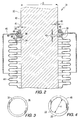
- a moveable contact sub-assembly 31 of a vacuum interrupter is provided with an electrode 32 having a groove 34 machined preferably around substantially the entire circumference of the electrode 32.
- the groove 34 is preferably machined to a width 43 of at least about 0.055 to 0.065 inches and a depth 45 of at least about 0.035 to 0.045 inches.
- an apparatus such as a spiral retaining ring 36 is disposed in the groove 34.
- the spiral retaining ring 36 has a first portion 38 extending into the groove 34 and a second portion 40 extending a distance 41 from the exterior surface 42 of the electrode 32.
- the first portion 38 preferably substantially fills the groove 34.
- the spiral retaining ring 36 may have a gap 37 disposed in a portion of its circumference.
- the spiral retaining ring 36 is preferably embodied as a conventional radial spring which is capable of expansion and contraction about its geometric center and which can extend around the circumference of the electrode 32 for more than one revolution and preferably for at least two revolutions.
- spiral retaining ring 36 can be any retaining ring suitable for providing adequate support to components which are brazed to form a vacuum tight seal in subsequent manufacture.
- Components including the bellows 44 and bellows shield 46 are stacked onto the second portion 40 of the spiral retaining ring 36.
- a component retaining ring 48 is circumferentially engaged around the electrode 32 in substantially intimate contact with the stacked components, which may include the bellows 44 and the bellows shield 46.
- the component retaining ring 48 is structured to contain or clamp securely the stack of components between the component retaining ring 48 and the second portion 40 of the spiral retaining ring 36.
- the component retaining ring 48 need not extend substantially continuously around the entire circumference of the electrode 32, but it must exert sufficient force against a stack of components to enable a subsequent brazing operation to establish a vacuum seal for the clamped stack of components.
- the component retaining ring 48 can be provided with alternating projection regions 20 and relief regions 22.
- the component retaining ring 48 can also have a structure substantially the same as the spiral retaining ring 36 discussed previously.
- the component retaining ring 48 can also be provided with an inside diameter d which is less than the outside diameter D of the electrode 32, so that the component retaining ring 48 "bites" into the electrode 32, particularly with the projection regions 20, when it is positioned around the circumference of the electrode 32 and is used to clamp and secure components such as the bellows 44 and bellows shield 46.
- braze material 49 is applied to selected areas between and among the stack of components, the electrode, and the retaining rings. This provides a vacuum seal within the sub-assembly 31 for its inclusion in a vacuum interrupter in subsequent manufacturing operations.
- the braze material 49 can be provided as a conventional solid type braze material which melts and adheres to the sub-assembly and its components in a heating operation associated with the brazing operation.
- the electrode 32 is conventionally composed of copper or a copper alloy.
- the bellows 44 and bellows shield 46 are preferably composed of stainless steel.
- the bellows 44 is preferably provided as a thin metal, conventional bellows.
- the retaining ring 36 preferably has a generally rectangular cross-section.
- the retaining ring 36 is composed of a material selected from the group consisting of stainless steel, carbon steel, and spring steel.
- the electrode 52 has a depth 54 of material machined and removed from the electrode 52.
- the machining process forms a ledge 56 which provides support for the electrode 52 as it rests on the ledge 56 in stable and substantially intimate contact with an end plate 58.
- the electrode 52 is held in place substantially by the force exerted by the weight of electrode 52 as it bears against end plate 58.
- Braze material 60 is then applied to seal the junction points between electrode 52 and end plate 58.
- the stationary contact sub-assembly 71 comprises an electrode 72 which has a groove 74 machined into the electrode 72 which extends around substantially the entire circumference of the electrode 72.
- a spiral retaining ring 76 is disposed in the groove 74 and has a first portion 78 extending into the groove 74 of the electrode 72, and a second portion 80 extending from an exterior surface 82 of the electrode 72.
- the second portion 80 of the spiral retaining ring 76 provides stable and intimate structural support with an end plate 84 against the force of gravity.
- the second portion 80 extends a distance 85 from the exterior surface 82 of the electrode 72.
- the groove 74 is machined into the electrode 72 to a depth 86 and a width 87.
- the depth 86 is preferably from about 0.035 to 0.045 inches.
- the width 87 of the groove 74 is preferably from about 0.055 to 0.065 inches.
- a braze material 88 is provided to braze the junctions of contact between and among the retaining ring 76, the end plate 84, and the electrode 72.
- the spiral retaining ring 76 is preferably generally rectangular in cross-section and extends round the circumference of the electrode 72 for preferably at least two revolutions.
- a method for assembling a vacuum interrupter sub-assembly begins by machining a circumferential groove into an electrode.
- the machining step may be performed with a hand lathe or on an automatic or CNC lathe.
- the electrode is stabilized in a fixture during assembly.
- a support device having first and second portions, such as a spiral retaining ring, is inserted with its first portion releasably engaged within the circumferential groove.
- the second portion of the support device extends beyond the exterior surface of the electrode and provides a support ledge for components which are then stacked onto the support ledge.
- the components are securely and rigidly clamped together on the support ledge by an apparatus such as a spiral retaining ring.
- the spiral retaining ring and other components are then brazed to establish a vacuum tight seal within the vacuum interrupter and to provide electrical contact between the spiral retaining ring and the electrode.
Landscapes
- Manufacture Of Switches (AREA)
- High-Tension Arc-Extinguishing Switches Without Spraying Means (AREA)
Abstract
Description
Claims (13)
- A vacuum interrupter contact assembly, comprising:an elongated electrode (32) having a circumferential groove (34) formed a selected depth (45) into said electrode (32);support means (36) having a first portion (30) disposed in said groove (34) and a second portion (40) extending a distance from the exterior (42) of said electrode (32);at least one vacuum interrupter component (44, 46) supported on said support means (36);clamping means (48), engaged around the circumference of said electrode (32), for clamping said at least one vacuum interrupter component (44, 46) against said support means (36); and,a braze (49) sealingly disposed on said clamping means (40) and said at least one vacuum interrupter component (44, 46) to establish a vacuum seal.
- The assembly of Claim 1, wherein said at least one vacuum interrupter component (44, 46) includes a bellows (44) and a bellows shield (46) supported on said support means (36).
- The assembly of Claim 1, wherein said groove (34) extends around substantially the entire circumference of said electrode (32).
- The assembly of Claim 1, wherein said support means (36) includes a spiral retaining ring (36) having a generally rectangular cross-section.
- The assembly of Claim 1, wherein said clamping means (48) includes alternating protection (20) and relief (22) regions extending around said circumference of said electrode (32).
- The assembly of Claim 1, wherein said support means (36) extends round said electrode (32) for at least two revolutions.
- An assembly for stabilizing and brazing a vacuum interrupter sub-assembly (71), comprising:an elongated electrode (72) having a circumferential groove (74) formed in said electrode (72);support means (76), having a first portion (78) disposed in said groove (74) and a second portion (80) extending a distance (85) from the exterior (82) of said electrode (72);an end plate (84) supported against said second portion (80) of said support means (76); and,a braze (88) sealingly disposed on said support means (76) and said end plate (84).
- The assembly of Claim 7, wherein said groove (74) extends around substantially the entire circumference of said electrode (72).
- The assembly of Claim 7, wherein said support means (76) includes a spiral retaining ring (76) having a generally rectangular cross-section.
- The assembly of Claim 7, wherein said support means (76) extends around the circumference of said electrode (72) for at least two revolutions.
- A method for stabilizing and brazing a vacuum interrupter contact sub-assembly (31) comprising:machining a circumferential groove (34) a selected depth (45) into an electrode (32);providing support means (36), having first (38) and second (40) portions;inserting said first portion (38) into said groove (34) to engage said support means (36);stacking at least one component (44, 46) of said vacuum interrupter onto said second portion (40) to support said at least one component (44, 46);clamping said component (44, 46) against said second portion (40) with a clamping means (48); andbrazing said clamping means (48) and said at least one component (44, 46) to establish a vacuum seal within said sub-assembly (31).
- The method of Claim 11, wherein said clamping said at least one component (44, 46) includes clamping a bellows shield (46) to a bellows (44) against said second portion (40).
- A method for stabilizing an elongated vacuum interrupter electrode (72) and its associated components for brazing in a vacuum interrupter sub-assembly (71), comprising:machining a circumferential groove (74) in said electrode (72);providing support means (76), having first (78) and second (80) portions;positioning said first portion (78) in said groove (74);stacking an end plate (84) against said second portion (80); and,brazing said support means (76) to said electrode (72) and to said end plate (84).
Applications Claiming Priority (2)
| Application Number | Priority Date | Filing Date | Title |
|---|---|---|---|
| US326966 | 1999-06-07 | ||
| US09/326,966 US6043446A (en) | 1999-06-07 | 1999-06-07 | Vacuum switch including shield and bellows mounted on electrode support structure located in electrode circumferential groove |
Publications (2)
| Publication Number | Publication Date |
|---|---|
| EP1059651A2 true EP1059651A2 (en) | 2000-12-13 |
| EP1059651A3 EP1059651A3 (en) | 2002-07-03 |
Family
ID=23274543
Family Applications (1)
| Application Number | Title | Priority Date | Filing Date |
|---|---|---|---|
| EP00111270A Withdrawn EP1059651A3 (en) | 1999-06-07 | 2000-05-25 | Apparatus and associated method for supporting a vacuum interrupter sub-assembly during manufacture |
Country Status (6)
| Country | Link |
|---|---|
| US (1) | US6043446A (en) |
| EP (1) | EP1059651A3 (en) |
| JP (1) | JP3513082B2 (en) |
| KR (1) | KR20010020942A (en) |
| CN (1) | CN1186794C (en) |
| ZA (1) | ZA200002772B (en) |
Families Citing this family (10)
| Publication number | Priority date | Publication date | Assignee | Title |
|---|---|---|---|---|
| US6417473B1 (en) * | 2000-07-14 | 2002-07-09 | Eaton Corporation | Method and apparatus for mounting vapor shield in vacuum interrupter and vacuum interrupter incorporating same |
| KR100475063B1 (en) * | 2002-03-07 | 2005-03-10 | 엘지산전 주식회사 | The bellows contacting device of vacuum interrupter for vacuum circuit breaker |
| US20050181090A1 (en) * | 2002-12-06 | 2005-08-18 | Mold-Masters Limited | Injection molding nozzle with embedded and removable heaters |
| JP4765538B2 (en) * | 2005-10-20 | 2011-09-07 | 富士電機機器制御株式会社 | Vacuum valve, vacuum valve manufacturing method |
| US8269130B2 (en) * | 2010-02-24 | 2012-09-18 | Eaton Corporation | Retainer, vacuum interrupter, and electrical switching apparatus including the same |
| CN102884601B (en) * | 2010-05-07 | 2015-02-18 | 三菱电机株式会社 | Vacuum valve |
| US8324521B2 (en) * | 2010-11-15 | 2012-12-04 | Eaton Corporation | Bellows for use in vacuum interrupters |
| KR101697580B1 (en) * | 2015-02-23 | 2017-02-01 | 엘에스산전 주식회사 | Vacuum Interrupter |
| DE102015216911B4 (en) * | 2015-09-03 | 2018-10-31 | Siemens Aktiengesellschaft | Vacuum interrupter with a holding element holder and / or a holding element and method for producing such |
| DE112021007601T5 (en) * | 2021-04-28 | 2024-02-22 | Mitsubishi Electric Corporation | Circuit breaker |
Family Cites Families (9)
| Publication number | Priority date | Publication date | Assignee | Title |
|---|---|---|---|---|
| US3996437A (en) * | 1973-12-03 | 1976-12-07 | Cutler-Hammer, Inc. | Vacuum contactor for motor control and method of making |
| US4081640A (en) * | 1976-04-19 | 1978-03-28 | General Electric Company | Compact vacuum switch for high voltage circuit interruption |
| JPS5717527A (en) * | 1980-07-07 | 1982-01-29 | Meidensha Electric Mfg Co Ltd | Vacuum breaker |
| JPS5715319A (en) * | 1980-07-01 | 1982-01-26 | Meidensha Electric Mfg Co Ltd | Vacuum breaker and method of producing same |
| US4499349A (en) * | 1981-11-20 | 1985-02-12 | Kabushiki Kaisha Meidensha | Vacuum interrupter |
| US4707577A (en) * | 1986-04-05 | 1987-11-17 | Kabushiki Kaisha Meidensha | Vacuum interrupter |
| CH686326A5 (en) * | 1993-08-27 | 1996-02-29 | Secheron Sa | Switch with a Vakuumschaltroehre. |
| US5793008A (en) * | 1996-11-01 | 1998-08-11 | Eaton Corporation | Vacuum interrupter with arc diffusing contact design |
| US5777287A (en) * | 1996-12-19 | 1998-07-07 | Eaton Corporation | Axial magnetic field coil for vacuum interrupter |
-
1999
- 1999-06-07 US US09/326,966 patent/US6043446A/en not_active Expired - Lifetime
-
2000
- 2000-05-25 EP EP00111270A patent/EP1059651A3/en not_active Withdrawn
- 2000-05-30 JP JP2000160433A patent/JP3513082B2/en not_active Expired - Fee Related
- 2000-06-02 KR KR1020000030292A patent/KR20010020942A/en not_active Ceased
- 2000-06-02 ZA ZA200002772A patent/ZA200002772B/en unknown
- 2000-06-07 CN CNB001180002A patent/CN1186794C/en not_active Expired - Fee Related
Also Published As
| Publication number | Publication date |
|---|---|
| ZA200002772B (en) | 2000-12-14 |
| KR20010020942A (en) | 2001-03-15 |
| JP2001006503A (en) | 2001-01-12 |
| CN1276615A (en) | 2000-12-13 |
| CN1186794C (en) | 2005-01-26 |
| JP3513082B2 (en) | 2004-03-31 |
| US6043446A (en) | 2000-03-28 |
| EP1059651A3 (en) | 2002-07-03 |
Similar Documents
| Publication | Publication Date | Title |
|---|---|---|
| US6043446A (en) | Vacuum switch including shield and bellows mounted on electrode support structure located in electrode circumferential groove | |
| US7721428B2 (en) | Method for making an electrode assembly | |
| EP2804297B1 (en) | Squirrel-cage rotor assembly with electron beam welded end caps | |
| US8365392B2 (en) | Method of fabricating a rotor assembly for an electric motor | |
| EP0183902A2 (en) | Method of attaching segments to cutting tool | |
| EP0660353B1 (en) | Vacuum valve and method of manufacturing the same | |
| KR100443325B1 (en) | Clad end seal for vacuum interrupter | |
| EP0370479A1 (en) | Method of mounting a replaceable emi spring strip | |
| EP0129080B1 (en) | Vacuum interrupter | |
| EP1456862B1 (en) | Solder ring for production of vacuum tube and method for the production of such a solder ring and of a vacuum tube | |
| JPH09274836A (en) | Vacuum valve and electrode manufacturing method thereof | |
| JPS6239954B2 (en) | ||
| JP2538864B2 (en) | Anode structure of magnetron and manufacturing method thereof | |
| EP0677354A1 (en) | Method for manufacturing, by capacitor-discharge welding, metal-plate radiator elements for domestic heating systems, and radiator element obtained therewith | |
| EP0744813A2 (en) | Induction motor rotor with laminated end rings and method for making the same | |
| GB2036608A (en) | Method of manufacturing centre electrodes for spark plugs | |
| JPS6048986B2 (en) | Manufacturing method of induction motor rotor | |
| SU1721713A1 (en) | Shielded stator of electric machine and method of its manufacture | |
| CN115091096A (en) | Flat wire motor welding tool and welding method | |
| JPS5617191A (en) | Resistance pressure welding method of molybdenum or molybdenum alloy | |
| JPH09231879A (en) | Vacuum valve and method of manufacturing the same | |
| JPS60189127A (en) | Method of producing vacuum switch | |
| Surzenkov et al. | Longer service life with diffusion welding | |
| JPH06137273A (en) | Compressor container and manufacture thereof | |
| JPH01228674A (en) | Welding method |
Legal Events
| Date | Code | Title | Description |
|---|---|---|---|
| PUAI | Public reference made under article 153(3) epc to a published international application that has entered the european phase |
Free format text: ORIGINAL CODE: 0009012 |
|
| AK | Designated contracting states |
Kind code of ref document: A2 Designated state(s): AT BE CH CY DE DK ES FI FR GB GR IE IT LI LU MC NL PT SE |
|
| AX | Request for extension of the european patent |
Free format text: AL;LT;LV;MK;RO;SI |
|
| PUAL | Search report despatched |
Free format text: ORIGINAL CODE: 0009013 |
|
| AK | Designated contracting states |
Kind code of ref document: A3 Designated state(s): AT BE CH CY DE DK ES FI FR GB GR IE IT LI LU MC NL PT SE |
|
| AX | Request for extension of the european patent |
Free format text: AL;LT;LV;MK;RO;SI |
|
| 17P | Request for examination filed |
Effective date: 20021021 |
|
| AKX | Designation fees paid |
Designated state(s): DE FR GB IT NL |
|
| 17Q | First examination report despatched |
Effective date: 20030305 |
|
| STAA | Information on the status of an ep patent application or granted ep patent |
Free format text: STATUS: THE APPLICATION IS DEEMED TO BE WITHDRAWN |
|
| 18D | Application deemed to be withdrawn |
Effective date: 20040630 |