EP1059546A2 - Multi-mode optical fiber having improved refractive index profile and devices comprising same - Google Patents
Multi-mode optical fiber having improved refractive index profile and devices comprising same Download PDFInfo
- Publication number
- EP1059546A2 EP1059546A2 EP00304620A EP00304620A EP1059546A2 EP 1059546 A2 EP1059546 A2 EP 1059546A2 EP 00304620 A EP00304620 A EP 00304620A EP 00304620 A EP00304620 A EP 00304620A EP 1059546 A2 EP1059546 A2 EP 1059546A2
- Authority
- EP
- European Patent Office
- Prior art keywords
- core
- profile
- refractive index
- fiber
- index
- Prior art date
- Legal status (The legal status is an assumption and is not a legal conclusion. Google has not performed a legal analysis and makes no representation as to the accuracy of the status listed.)
- Withdrawn
Links
Images


Classifications
-
- G—PHYSICS
- G02—OPTICS
- G02B—OPTICAL ELEMENTS, SYSTEMS OR APPARATUS
- G02B6/00—Light guides; Structural details of arrangements comprising light guides and other optical elements, e.g. couplings
- G02B6/02—Optical fibres with cladding with or without a coating
- G02B6/028—Optical fibres with cladding with or without a coating with core or cladding having graded refractive index
-
- G—PHYSICS
- G02—OPTICS
- G02B—OPTICAL ELEMENTS, SYSTEMS OR APPARATUS
- G02B6/00—Light guides; Structural details of arrangements comprising light guides and other optical elements, e.g. couplings
- G02B6/02—Optical fibres with cladding with or without a coating
- G02B6/028—Optical fibres with cladding with or without a coating with core or cladding having graded refractive index
- G02B6/0288—Multimode fibre, e.g. graded index core for compensating modal dispersion
-
- G—PHYSICS
- G02—OPTICS
- G02B—OPTICAL ELEMENTS, SYSTEMS OR APPARATUS
- G02B6/00—Light guides; Structural details of arrangements comprising light guides and other optical elements, e.g. couplings
- G02B6/02—Optical fibres with cladding with or without a coating
-
- G—PHYSICS
- G02—OPTICS
- G02B—OPTICAL ELEMENTS, SYSTEMS OR APPARATUS
- G02B6/00—Light guides; Structural details of arrangements comprising light guides and other optical elements, e.g. couplings
- G02B6/02—Optical fibres with cladding with or without a coating
- G02B6/036—Optical fibres with cladding with or without a coating core or cladding comprising multiple layers
- G02B6/03605—Highest refractive index not on central axis
- G02B6/03611—Highest index adjacent to central axis region, e.g. annular core, coaxial ring, centreline depression affecting waveguiding
-
- G—PHYSICS
- G02—OPTICS
- G02B—OPTICAL ELEMENTS, SYSTEMS OR APPARATUS
- G02B6/00—Light guides; Structural details of arrangements comprising light guides and other optical elements, e.g. couplings
- G02B6/02—Optical fibres with cladding with or without a coating
- G02B6/036—Optical fibres with cladding with or without a coating core or cladding comprising multiple layers
- G02B6/03616—Optical fibres characterised both by the number of different refractive index layers around the central core segment, i.e. around the innermost high index core layer, and their relative refractive index difference
- G02B6/03622—Optical fibres characterised both by the number of different refractive index layers around the central core segment, i.e. around the innermost high index core layer, and their relative refractive index difference having 2 layers only
- G02B6/03633—Optical fibres characterised both by the number of different refractive index layers around the central core segment, i.e. around the innermost high index core layer, and their relative refractive index difference having 2 layers only arranged - -
Definitions
- the present invention relates to a multi-mode optical fiber having an improved refractive index profile and to a communications system comprising the inventive fiber.
- an optical fiber comprises an inner core fabricated from a dielectric material having a certain index of refraction and a cladding surrounding the core.
- the cladding is comprised of a material having a lower index of refraction than the core.
- Fibers can be fabricated to propagate light with a single mode or multiple modes; an optical fiber which supports more than one guided mode is referred to as a multi-mode fiber.
- Multi-mode fibers typically have a larger core diameter than single-mode fibers to enable a larger number of modes to pass through the fiber. Additional design constraints are posed by multi-mode applications. Such constraints may include, for example, the choice of materials used to fabricate the core and cladding and the refractive index profile of the fiber (e.g., the profile reflects the radial variation in refractive index from the center of the fiber to the outer circumference of the cladding).
- Various types of refractive index profiles are known, e.g., step index, graded index, depressed clad, or W-type variety.
- the group velocities of the various modes in multi-mode fibers should be as close to equal as possible.
- the differential group velocities can be controlled by grading the refractive index of the material comprising the core, which means specifying a functional form of the index as a function of the fiber radius.
- ⁇ and ⁇ are free parameters.
- the optimal choice of parameters depends on the properties of the materials comprising the fiber and the intended application.
- a common side effect of the MCVD process is a pronounced index depression, or dip, in the center of the fiber, which results in poorly compensated low order modes (i.e. those with small principle mode number).
- poorly compensated low order modes i.e. those with small principle mode number.
- the modes which have fields confined near to the central axis of the fiber have substantially different group velocities than the majority of the modes.
- Poorly compensated low order modes can dramatically affect fiber performance for certain applications, e.g. under launch from a semiconductor laser.
- this profile involves an extension of the alpha shape below the cladding (e.g., outside the core/cladding boundary region), with a negative cladding jump and then a further numerical refinement of the shape of the profile.
- cladding e.g., outside the core/cladding boundary region
- a further numerical refinement of the shape of the profile See also Okamoto et al ., "Analysis of Wave Propagation in Optical Fibers Having Core with a-Power Refractive-Index Distribution and Uniform Cladding," IEEE TRANS. MICROWAVE THEORY AND TECHNIQUES, Vol. MTT-24, No. 7 (July 1976), at p. 416 (incorporated herein), discussing use of numerical analysis to propose a similar profile. While such profiles may be advantageous in leading to high bandwidths, they are difficult to manufacture, and it is believed they may lead to leaky modes.
- a parabolic index profile is combined with a cladding jump, which leads to higher bandwidths than with a parabolic profile with no cladding jump.
- the core has a refractive index profile that has a parabolic distribution and is surrounded by a cladding having a constant refractive index.
- the instant invention provides a multi-mode fiber having a refractive index profile that is relatively easy to manufacture and yet improves the behavior of high-order modes propagated by the fiber and compensates for the presence of a center dip, thereby improving the behavior of low order modes. Further advantages may appear more fully upon considering the description given below.
- a multi-mode fiber having increased performance may be made by modifying a conventional ⁇ -profile by (i) modifying the profile near the core-cladding boundary, to improve the behavior of high-order modes relative to that of an ⁇ -profile, and (ii) adding an index ridge near the center of the fiber to compensate for the presence of a center dip, thereby improving the behavior of the low-order modes.
- Gains in performance also may be achieved by modifying the profile with a ripple adjacent the core-cladding boundary.
- This invention provides a multi-mode fiber having a refractive index profile that is relatively easy to manufacture, improves the behavior of high order modes propagated by the fiber, and compensates for the presence of a center dip, thereby improving the behavior of low order modes.
- the conventional ⁇ -profile may be modified in at least one of three ways: (i) a step may be formed in the index profile at the boundary of the core and cladding regions, in combination with a linear correction; (ii) a ripple may be added near the core-cladding boundary, in combination with a linear correction, either with or without an index step; or (iii) an annular ridge may be formed in the index profile of an ⁇ -profile with a center dip defect.
- annular ridge (iii) may be applied in combination with the step in the index profile (i), and/or in combination with the ripple (ii).
- the step (i) may be formed without the ripple, and the ripple (ii) may be formed without the step.
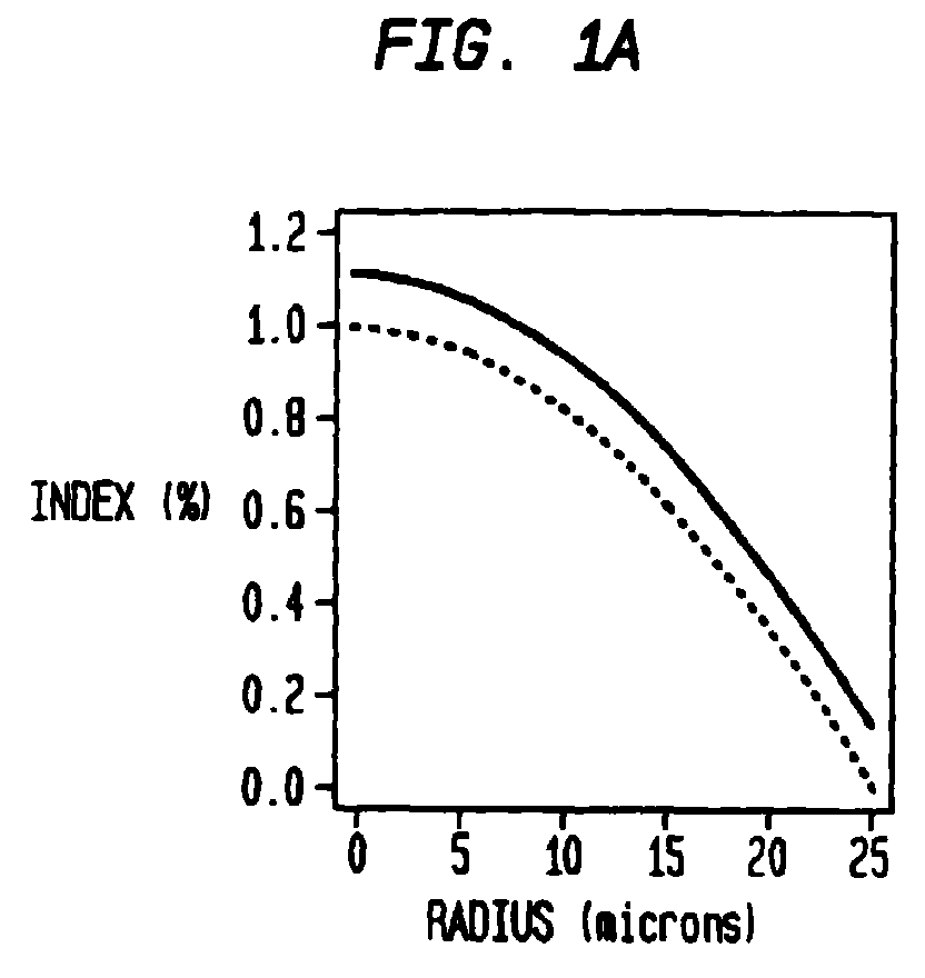
- FIG. 1A shows a conventional optimal ⁇ -profile (dotted line) and a modified profile (solid line).
- the modified profile has been formed by the first of the three options identified above, that is, a step has been added in the index at the boundary between the core and the cladding, and a linear correction was made to the index profile with the step.
- FIG. 1B shows the profile difference between the optimal ⁇ -profile and this modified profile of FIG. 1A.
- the gradual variation in index for radii below about 21 microns is an artifact of the particular definition of an ⁇ -profile used to generate the modified profile.
- FIG. 3A shows a conventional optimal ⁇ -profile (dotted line) and a modified profile (solid line) formed with both the first and second options referenced above.
- the solid line reflects a fiber where a step has been added in the index at the boundary between the core and cladding, a linear correction has been added, and a small ripple has been introduced into the profile.
- FIG. 3B shows the profile difference between the optimal profile and modified profile of FIG. 3A, which particularly illustrates the ripple introduced into the profile.
- the class of profile shapes according to the invention may be mathematically described. Mathematically, the class of profiles may be written as where ⁇ (1-(r/r core ) ⁇ ) is a conventional ⁇ -profile, J >0 is a step in index at the core-cladding boundary, f ripple (r) is described below, and f linear (r,r 0 ) is defined by
- Equation (1) may be applied to achieve a plurality of profiles that approximately optimize the behavior of the high-order modes; in other words, there is a certain amount of freedom in the optimal design.
- a method by which one may arrive at a preferred design for a given application comprises the following steps: selecting the parameters r core and ⁇ of the ⁇ -profile which is to be modified, along with a wavelength ⁇ at which the fiber will be operated; selecting a value of the index step J , which preferably is in the range of 0 to 0.5%; and then applying a computer code to obtain values for the parameters r 0 and m in Equation (2).
- a computer code that may be applied is described in T.A.
- the factor f ripple can either be 0, or it may have a certain value for use in further optimizing the fiber performance.
- the above method was applied to arrive at a preferred design for a fiber having a core comprising germania-doped silica surrounded by a cladding comprising pure silica.
- the value for f ripple was set at 0.
- the results of this procedure are reflected in the modified profile shown in FIGS. 1A and 1B.
- FIGS. 3A-3B The results of the procedure where the additional term f ripple (r) has been added are shown in FIGS. 3A-3B.
- FIGS. 5A-5B The results of the procedure where the value for J is selected as 0 are shown in FIGS. 5A-5B.
- a ripple has been added in addition to a linear correction near the core-cladding boundary, without an index step.
- FIG. 5A shows a conventional optimal ⁇ -profile (dotted line), and a modified profile (solid line) formed with a linear correction adjacent to the cladding and with a small ripple introduced into the profile without a cladding jump;
- FIG. 5B shows the profile difference between the optimal profile and modified profile of FIG. 5A, illustrating the correction introduced into the profile.
- FIGS. 2, 4, and 6 show the predicted modal delays of the fibers illustrated in FIGS. 1A-1B, 3A-3B, and 5A-5B, respectively.
- Modal delays are reported per km (i.e. the inverses of the group velocities of the various modes) as a function of principle mode number for a fiber having a modified profile (represented by +) and one having a conventional ⁇ -profile (represented by o).
- the delays of the fiber having a modified profile (+) are more equal than those of a fiber having a conventional ⁇ -profile (o).
- the decreased spreading in the modal delays achieved with the modified profiles is advantageous for a number of reasons. For example, one advantage is that the overfilled bandwidths (included on the plots), are likely higher. Also, if the inventive fiber is used in a system comprising a laser launch with one or more connectors between fibers, the tolerances on the launch condition and the connectors may be more forgiving than if a fiber having a conventional profile were incorporated in the system. For instance, in certain applications the use of a conventional fiber may dictate that no light be coupled into the high-order modes, whereas with the inventive fiber this coupling may be present.
- FIG. 7B Another embodiment of the invention is shown in FIG. 7B, illustrating a modified profile comprising an index ridge proximal the center dip of a conventional ⁇ -profile.
- This profile substantially improves the behavior of low order modes.
- an index ridge is added proximal the center dip of a conventional ⁇ -profile (shown for comparison in FIG. 7A). If the ridge and center dip are confined within a small percentage (e.g., about five percent) of the core radius, the group velocities of the modes of the fiber will be determined only by the integral of the index in the vicinity of the center, not on the detailed shape near the center. Thus, the shape near the center becomes less significant and the presence of a center dip has a lesser impact upon fiber performance.
- a small percentage e.g., about five percent
- the radius below which the ridge must be confined will depend on the wavelength ⁇ transmitted by the fiber and the fiber design (e.g., materials comprising the core and the cladding, the diameter of the core and cladding, and other parameters).
- the profile of FIG. 7B reflects a fiber having a core comprising germania doped silica surrounded by a cladding comprising pure silica for transmitting a wavelength ⁇ of about 850 nm.
- the ridge is preferably disposed at a distance from the center that is within about four percentage of the core radius.
- Benefits achieved with the modified index profile of FIG. 7B may also depend upon the height and width of the ridge profile.
- the height and width of the ridge are selected to cancel the center dip in the sense that the total integral of the index in the vicinity of the center is equal to that of a pure ⁇ -profile.
- the fiber then will exhibit the same properties as a fiber having a pure ⁇ -profile.
- the benefits will be greater as the radius to which the ridge is confined is decreased; i.e. preferably the ridge is confined as close to the center as possible.
- benefits also are obtained with wider ridges, for example, ridges confined to about 10-20% of the core radius, for typical multimode fiber designs.
- FIG. 8 illustrates the modal delays from the two profiles shown in FIGS. 7A-7B.
- the delays of the low-order modes of the fiber with the ridge have much less spread than those of the fiber with only a center dip.
- the bandwidth of the fiber with the ridge is much higher than that of the fiber without the ridge. For purposes of illustration, bandwidths have been predicted under the assumed launch condition of the first four principle mode groups excited.
- the inventive fiber may comprise part of an optical fiber communication system that further comprises elements such as a transmitter 100, a receiver 104, and an optical path 102 connecting transmitter and receiver, possibly with one or more amplifiers 106, disposed along the optical path.
- the inventive fiber may be utilized throughout the optical path or at select regions of the optical path, e.g., section 110, and may be coupled with conventional fibers or devices.
Landscapes
- Physics & Mathematics (AREA)
- General Physics & Mathematics (AREA)
- Optics & Photonics (AREA)
- Chemical & Material Sciences (AREA)
- Dispersion Chemistry (AREA)
- Optical Communication System (AREA)
- Lasers (AREA)
- Optical Fibers, Optical Fiber Cores, And Optical Fiber Bundles (AREA)
Abstract
Description


Claims (10)
- An article including a multi-mode optical fiber, the optical fiber comprisinga core fabricated with a material having a predetermined refractive index;a cladding surrounding the core having a refractive index that differs from the refractive index of the core, the interface at which the cladding meets the core defining a boundary region,in which the core has a modified refractive index profile, the modified refractive index profile comprising an α-profile modified by at least one of (a) a step in the index adjacent the boundary region in combination with a linear correction; (b) a ripple adjacent the boundary region in combination with a linear correction; and (c) an index ridge adjacent the center of the fiber region
- The article of claim 1, in which the modified refractive index profile comprises a step in the index adjacent the boundary region in combination with a linear correction and a ripple adjacent the boundary region.
- The article of claim 1, in which the modified refractive index profile comprises a ripple adjacent the boundary region in combination with a linear correction without an index step.
- The article of claim 1, in which the modified refractive index profile is defined by the equation,where Δ (1-(r/rcore)α) is a conventional α-profile, J > 0 is the step in index adjacent the boundary region, f ripple(r) is a parameter defining the ripple, and f linear(r,r0) is defined by


- An article including a multi-mode optical fiber, the optical fiber comprisinga core fabricated with a material having a predetermined refractive index;a cladding surrounding the core having a refractive index that differs from the refractive index of the core, the interface at which the cladding meets the core defining a boundary region,in which the core has a modified refractive index profile having the shape of an α-profile modified by a step in the index adjacent the boundary region and a linear correction in the region where r > r 0 where r 0 ≥ 0.7r core, r is the fiber radius, and r core is the radius of the fiber core.
- The article of claim 5, in which the modified refractive index profile further comprises a ripple adjacent the core region.
- An article including a multi-mode optical fiber, the optical fiber comprisinga core having a define core radius and fabricated with a material having a predetermined refractive index;a cladding surrounding the core having a refractive index that differs from the refractive index of the core, in which a ridge or trough in the refractive index of the core is disposed within twenty percent of the radius of the core to compensate for the presence of a center dip or peak, respectively.
- The article of claim 7, in which the ridge or trough is disposed within five percent of the radius of the core.
- A system comprising a transmitter and a detector connected by one or more multimode fibers according to claim 1.
- A system comprising a transmitter and a detector connected by one or more multimode fibers according to claim 5.
Priority Applications (1)
| Application Number | Priority Date | Filing Date | Title |
|---|---|---|---|
| EP06003645A EP1657574A3 (en) | 1999-06-07 | 2000-05-31 | Multi-mode optical fiber having improved refrative index profile and devices comprising same |
Applications Claiming Priority (2)
| Application Number | Priority Date | Filing Date | Title |
|---|---|---|---|
| US326960 | 1999-06-07 | ||
| US09/326,960 US6292612B1 (en) | 1999-06-07 | 1999-06-07 | Multi-mode optical fiber having improved refractive index profile and devices comprising same |
Related Child Applications (1)
| Application Number | Title | Priority Date | Filing Date |
|---|---|---|---|
| EP06003645A Division EP1657574A3 (en) | 1999-06-07 | 2000-05-31 | Multi-mode optical fiber having improved refrative index profile and devices comprising same |
Publications (2)
| Publication Number | Publication Date |
|---|---|
| EP1059546A2 true EP1059546A2 (en) | 2000-12-13 |
| EP1059546A3 EP1059546A3 (en) | 2004-03-10 |
Family
ID=23274517
Family Applications (2)
| Application Number | Title | Priority Date | Filing Date |
|---|---|---|---|
| EP06003645A Withdrawn EP1657574A3 (en) | 1999-06-07 | 2000-05-31 | Multi-mode optical fiber having improved refrative index profile and devices comprising same |
| EP00304620A Withdrawn EP1059546A3 (en) | 1999-06-07 | 2000-05-31 | Multi-mode optical fiber having improved refractive index profile and devices comprising same |
Family Applications Before (1)
| Application Number | Title | Priority Date | Filing Date |
|---|---|---|---|
| EP06003645A Withdrawn EP1657574A3 (en) | 1999-06-07 | 2000-05-31 | Multi-mode optical fiber having improved refrative index profile and devices comprising same |
Country Status (6)
| Country | Link |
|---|---|
| US (1) | US6292612B1 (en) |
| EP (2) | EP1657574A3 (en) |
| KR (1) | KR20010007258A (en) |
| CN (1) | CN1276536A (en) |
| CA (1) | CA2310342A1 (en) |
| TW (1) | TW440724B (en) |
Cited By (1)
| Publication number | Priority date | Publication date | Assignee | Title |
|---|---|---|---|---|
| EP1498753A3 (en) * | 2003-07-18 | 2005-02-16 | Fujikura Ltd. | Graded-index multimode fiber and manufacturing method therefor |
Families Citing this family (34)
| Publication number | Priority date | Publication date | Assignee | Title |
|---|---|---|---|---|
| US6689463B2 (en) | 2001-12-18 | 2004-02-10 | Corning Incorporated | Secondary coating composition for optical fibers |
| KR100526516B1 (en) * | 2003-07-11 | 2005-11-08 | 삼성전자주식회사 | Graded-index optical fiber for high bit-rate and local area network |
| NL1024015C2 (en) | 2003-07-28 | 2005-02-01 | Draka Fibre Technology Bv | Multimode optical fiber provided with a refractive index profile, optical communication system using this and method for manufacturing such a fiber. |
| US7646955B2 (en) * | 2004-07-26 | 2010-01-12 | Corning Incorporated | Multimode optical fiber with low differential mode delay |
| FR2922657B1 (en) | 2007-10-23 | 2010-02-12 | Draka Comteq France | MULTIMODE FIBER. |
| FR2932932B1 (en) * | 2008-06-23 | 2010-08-13 | Draka Comteq France Sa | MULTIPLEX WAVE LENGTH OPTIC SYSTEM WITH MULTIMODE OPTIC FIBERS |
| FR2933779B1 (en) * | 2008-07-08 | 2010-08-27 | Draka Comteq France | MULTIMODE OPTIC FIBERS |
| US20100154478A1 (en) | 2008-12-01 | 2010-06-24 | Panduit Corp. | Multimode fiber having improved index profile |
| FR2940839B1 (en) * | 2009-01-08 | 2012-09-14 | Draka Comteq France | INDEX GRADIENT MULTIMODAL OPTICAL FIBER, METHODS FOR CHARACTERIZATION AND MANUFACTURE OF SUCH A FIBER |
| FR2946436B1 (en) | 2009-06-05 | 2011-12-09 | Draka Comteq France | MULTIMODE OPTICAL FIBER WITH LARGE BANDWIDTH WITH AN OPTIMIZED HEAT-SLEEVE INTERFACE |
| US8351027B2 (en) * | 2009-06-15 | 2013-01-08 | Panduit Corp. | Method and metric for selecting and designing multimode fiber for improved performance |
| FR2949870B1 (en) * | 2009-09-09 | 2011-12-16 | Draka Compteq France | MULTIMODE OPTICAL FIBER HAVING IMPROVED BENDING LOSSES |
| FR2953605B1 (en) * | 2009-12-03 | 2011-12-16 | Draka Comteq France | MULTIMODE OPTICAL FIBER WITH BROAD BANDWIDTH AND LOW BENDBACK LOSSES |
| FR2953030B1 (en) * | 2009-11-25 | 2011-11-18 | Draka Comteq France | MULTIMODE OPTICAL FIBER WITH LARGE BANDWIDTH WITH AN OPTIMIZED HEAT-SLEEVE INTERFACE |
| FR2953029B1 (en) * | 2009-11-25 | 2011-11-18 | Draka Comteq France | MULTIMODE OPTICAL FIBER WITH LARGE BANDWIDTH WITH AN OPTIMIZED HEAT-SLEEVE INTERFACE |
| FR2953606B1 (en) * | 2009-12-03 | 2012-04-27 | Draka Comteq France | MULTIMODE OPTICAL FIBER WITH BROAD BANDWIDTH AND LOW BENDBACK LOSSES |
| US9014525B2 (en) | 2009-09-09 | 2015-04-21 | Draka Comteq, B.V. | Trench-assisted multimode optical fiber |
| FR2957153B1 (en) * | 2010-03-02 | 2012-08-10 | Draka Comteq France | MULTIMODE OPTICAL FIBER WITH BROAD BANDWIDTH AND LOW BENDBACK LOSSES |
| FR2950156B1 (en) * | 2009-09-17 | 2011-11-18 | Draka Comteq France | MULTIMODE OPTIC FIBER |
| US7865050B1 (en) | 2010-02-16 | 2011-01-04 | Ofs Fitel, Llc | Equalizing modal delay of high order modes in bend insensitive multimode fiber |
| FR2966256B1 (en) | 2010-10-18 | 2012-11-16 | Draka Comteq France | MULTIMODE OPTICAL FIBER INSENSITIVE TO LOSSES BY |
| EP2482106B1 (en) | 2011-01-31 | 2014-06-04 | Draka Comteq B.V. | Multimode fiber |
| FR2971061B1 (en) | 2011-01-31 | 2013-02-08 | Draka Comteq France | BROAD BANDWIDTH OPTICAL FIBER WITH LOW CURB LOSSES |
| EP2503368A1 (en) | 2011-03-24 | 2012-09-26 | Draka Comteq B.V. | Multimode optical fiber with improved bend resistance |
| EP2506044A1 (en) | 2011-03-29 | 2012-10-03 | Draka Comteq B.V. | Multimode optical fiber |
| EP2518546B1 (en) | 2011-04-27 | 2018-06-20 | Draka Comteq B.V. | High-bandwidth, radiation-resistant multimode optical fiber |
| DK2541292T3 (en) | 2011-07-01 | 2014-12-01 | Draka Comteq Bv | A multimode optical fiber |
| US8565566B2 (en) | 2011-10-05 | 2013-10-22 | Sumitomo Electric Industries, Ltd. | Multi-mode optical fiber |
| US8565567B2 (en) | 2011-11-23 | 2013-10-22 | Sumitomo Electric Industries, Ltd. | Multi-mode optical fiber |
| US8798420B2 (en) * | 2012-03-14 | 2014-08-05 | Sumitomo Electric Industries, Ltd. | Multi-mode optical fiber |
| US8824848B1 (en) | 2013-06-10 | 2014-09-02 | Sumitomo Electric Industries, Ltd. | Multimode optical fiber including a core and a cladding |
| US8837888B1 (en) | 2013-08-02 | 2014-09-16 | Sumitomo Electric Industries, Ltd. | Multimode optical fiber including a core and a cladding |
| WO2018025857A1 (en) | 2016-08-02 | 2018-02-08 | 住友電気工業株式会社 | Optical fiber matrix production method and optical fiber production method |
| CN109669232B (en) * | 2019-01-17 | 2021-01-12 | 上海大学 | Single crystal semiconductor core optical fiber and method for manufacturing the same |
Family Cites Families (16)
| Publication number | Priority date | Publication date | Assignee | Title |
|---|---|---|---|---|
| US3823995A (en) * | 1972-03-30 | 1974-07-16 | Corning Glass Works | Method of forming light focusing fiber waveguide |
| US4033667A (en) * | 1975-09-12 | 1977-07-05 | Bell Telephone Laboratories, Incorporated | Multimode optical fiber |
| US4203743A (en) * | 1976-09-20 | 1980-05-20 | Hitachi, Ltd. | Method of producing optical fiber |
| GB1562032A (en) * | 1977-03-24 | 1980-03-05 | Standard Telephones Cables Ltd | Optical fibre manufacture |
| CA1170876A (en) * | 1980-12-29 | 1984-07-17 | Koichi Abe | Fiber with coarse index gradient |
| US4560247A (en) * | 1983-07-01 | 1985-12-24 | Quartz Et Silice | Large bandwidth optical fibers |
| JPS6140834A (en) * | 1984-07-31 | 1986-02-27 | Furukawa Electric Co Ltd:The | Preparation of parent material for optical fiber |
| JPS62123038A (en) * | 1985-11-25 | 1987-06-04 | Furukawa Electric Co Ltd:The | Production of parent material for optical fiber |
| EP0301797B1 (en) * | 1987-07-30 | 1993-12-08 | AT&T Corp. | Methods of making optical fiber and products produced thereby |
| DE3812140A1 (en) * | 1988-04-12 | 1989-11-02 | Schott Glaswerke | MONOMODE LIGHT FIBER |
| DE4001781C1 (en) * | 1990-01-23 | 1991-02-21 | Schott Glaswerke, 6500 Mainz, De | |
| US5278931A (en) * | 1992-12-31 | 1994-01-11 | Corning Incorporated | Low bend loss singlemode optical waveguide fiber |
| BR9500990A (en) * | 1995-03-28 | 1995-08-01 | Abc Algar | Optical waveguide |
| US5729645A (en) * | 1996-08-13 | 1998-03-17 | The Trustees Of The University Of Pennsylvania | Graded index optical fibers |
| EP0884614A1 (en) * | 1997-06-13 | 1998-12-16 | Sumitomo Electric Industries, Ltd. | Optical fiber |
| US5940567A (en) * | 1998-02-20 | 1999-08-17 | Photon-X, Inc. | Optical fibers having an inner core and an outer core |
-
1999
- 1999-06-07 US US09/326,960 patent/US6292612B1/en not_active Expired - Lifetime
-
2000
- 2000-05-30 CA CA002310342A patent/CA2310342A1/en not_active Abandoned
- 2000-05-31 EP EP06003645A patent/EP1657574A3/en not_active Withdrawn
- 2000-05-31 EP EP00304620A patent/EP1059546A3/en not_active Withdrawn
- 2000-06-02 TW TW089110807A patent/TW440724B/en not_active IP Right Cessation
- 2000-06-06 CN CN00117977A patent/CN1276536A/en active Pending
- 2000-06-07 KR KR1020000030982A patent/KR20010007258A/en not_active Withdrawn
Cited By (2)
| Publication number | Priority date | Publication date | Assignee | Title |
|---|---|---|---|---|
| EP1498753A3 (en) * | 2003-07-18 | 2005-02-16 | Fujikura Ltd. | Graded-index multimode fiber and manufacturing method therefor |
| US7043126B2 (en) | 2003-07-18 | 2006-05-09 | Fujikura Ltd. | Graded-index multimode fiber and manufacturing method therefor |
Also Published As
| Publication number | Publication date |
|---|---|
| EP1657574A2 (en) | 2006-05-17 |
| US6292612B1 (en) | 2001-09-18 |
| KR20010007258A (en) | 2001-01-26 |
| TW440724B (en) | 2001-06-16 |
| CA2310342A1 (en) | 2000-12-07 |
| EP1657574A3 (en) | 2006-05-31 |
| EP1059546A3 (en) | 2004-03-10 |
| CN1276536A (en) | 2000-12-13 |
Similar Documents
| Publication | Publication Date | Title |
|---|---|---|
| US6292612B1 (en) | Multi-mode optical fiber having improved refractive index profile and devices comprising same | |
| US4852968A (en) | Optical fiber comprising a refractive index trench | |
| JP5670164B2 (en) | Multimode optical fiber with low bending loss and reduced cladding effect | |
| JP5802383B2 (en) | High-band multimode optical fiber and optical fiber system | |
| JP5732234B2 (en) | High-band multimode optical fiber | |
| EP2299303B1 (en) | Multimode optical fibre with reduced bending losses | |
| EP0307228B1 (en) | Few-mode/single-mode fiber | |
| EP2339384B1 (en) | High-bandwidth multimode optical fiber having reduced bending losses | |
| JP5918545B2 (en) | Optical fiber with low bending loss and wide bandwidth | |
| US6212322B1 (en) | Positive dispersion low dispersion slope fiber | |
| US6879764B2 (en) | Dispersion shifted fiber having low dispersion slope | |
| JPH10300965A (en) | System with dispersion compensating optical fiber | |
| CN108700703A (en) | Less fundamental mode optical fibre used in mode division multiplexing | |
| KR100342711B1 (en) | Dispersion shifted fiber with triple clad | |
| JP6918983B2 (en) | Multimode fiber optics optimized to operate around 1060 nm, and corresponding multimode optics | |
| WO2007125540A1 (en) | Dispersion optimized optical fiber for wideband optical transmission | |
| US6442320B1 (en) | Limited mode dispersion compensating optical fiber | |
| CN109073825A (en) | Less fundamental mode optical fibre used in mode division multiplexing | |
| JP4132581B2 (en) | Apparatus including multimode optical fiber | |
| JP4568485B2 (en) | Single mode optical fiber and optical communication system | |
| KR20010053516A (en) | Single mode optical waveguide | |
| EP3492956A1 (en) | Non-zero dispersion shifted fiber with low cut off wavelength and large effective area |
Legal Events
| Date | Code | Title | Description |
|---|---|---|---|
| PUAI | Public reference made under article 153(3) epc to a published international application that has entered the european phase |
Free format text: ORIGINAL CODE: 0009012 |
|
| AK | Designated contracting states |
Kind code of ref document: A2 Designated state(s): AT BE CH CY DE DK ES FI FR GB GR IE IT LI LU MC NL PT SE |
|
| AX | Request for extension of the european patent |
Free format text: AL;LT;LV;MK;RO;SI |
|
| RIC1 | Information provided on ipc code assigned before grant |
Ipc: 7G 02B 6/22 B Ipc: 7G 02B 6/18 A |
|
| PUAL | Search report despatched |
Free format text: ORIGINAL CODE: 0009013 |
|
| AK | Designated contracting states |
Kind code of ref document: A3 Designated state(s): AT BE CH CY DE DK ES FI FR GB GR IE IT LI LU MC NL PT SE |
|
| AX | Request for extension of the european patent |
Extension state: AL LT LV MK RO SI |
|
| 17P | Request for examination filed |
Effective date: 20040430 |
|
| 17Q | First examination report despatched |
Effective date: 20040701 |
|
| AKX | Designation fees paid |
Designated state(s): DE FR GB IT NL |
|
| STAA | Information on the status of an ep patent application or granted ep patent |
Free format text: STATUS: THE APPLICATION IS DEEMED TO BE WITHDRAWN |
|
| 18D | Application deemed to be withdrawn |
Effective date: 20081102 |