EP1059541A2 - Interference rejection method for an automative radar CW/ICC system - Google Patents
Interference rejection method for an automative radar CW/ICC system Download PDFInfo
- Publication number
- EP1059541A2 EP1059541A2 EP00201678A EP00201678A EP1059541A2 EP 1059541 A2 EP1059541 A2 EP 1059541A2 EP 00201678 A EP00201678 A EP 00201678A EP 00201678 A EP00201678 A EP 00201678A EP 1059541 A2 EP1059541 A2 EP 1059541A2
- Authority
- EP
- European Patent Office
- Prior art keywords
- samples
- data
- variance
- array
- interference
- Prior art date
- Legal status (The legal status is an assumption and is not a legal conclusion. Google has not performed a legal analysis and makes no representation as to the accuracy of the status listed.)
- Withdrawn
Links
- 238000000034 method Methods 0.000 title claims abstract description 30
- 230000001052 transient effect Effects 0.000 claims abstract description 25
- 238000005070 sampling Methods 0.000 claims 2
- 230000004044 response Effects 0.000 description 7
- 238000010586 diagram Methods 0.000 description 6
- 230000008569 process Effects 0.000 description 3
- 238000004364 calculation method Methods 0.000 description 2
- 238000004590 computer program Methods 0.000 description 2
- 230000009471 action Effects 0.000 description 1
- 230000003044 adaptive effect Effects 0.000 description 1
- 238000006243 chemical reaction Methods 0.000 description 1
- 230000008878 coupling Effects 0.000 description 1
- 238000010168 coupling process Methods 0.000 description 1
- 238000005859 coupling reaction Methods 0.000 description 1
- 230000000694 effects Effects 0.000 description 1
- 230000007246 mechanism Effects 0.000 description 1
- 230000000116 mitigating effect Effects 0.000 description 1
- 230000004048 modification Effects 0.000 description 1
- 238000012986 modification Methods 0.000 description 1
- 230000035755 proliferation Effects 0.000 description 1
- 239000007787 solid Substances 0.000 description 1
- 230000003595 spectral effect Effects 0.000 description 1
- 238000001228 spectrum Methods 0.000 description 1
- 230000009466 transformation Effects 0.000 description 1
Images

Classifications
-
- G—PHYSICS
- G01—MEASURING; TESTING
- G01S—RADIO DIRECTION-FINDING; RADIO NAVIGATION; DETERMINING DISTANCE OR VELOCITY BY USE OF RADIO WAVES; LOCATING OR PRESENCE-DETECTING BY USE OF THE REFLECTION OR RERADIATION OF RADIO WAVES; ANALOGOUS ARRANGEMENTS USING OTHER WAVES
- G01S7/00—Details of systems according to groups G01S13/00, G01S15/00, G01S17/00
- G01S7/02—Details of systems according to groups G01S13/00, G01S15/00, G01S17/00 of systems according to group G01S13/00
- G01S7/023—Interference mitigation, e.g. reducing or avoiding non-intentional interference with other HF-transmitters, base station transmitters for mobile communication or other radar systems, e.g. using electro-magnetic interference [EMI] reduction techniques
-
- G—PHYSICS
- G01—MEASURING; TESTING
- G01S—RADIO DIRECTION-FINDING; RADIO NAVIGATION; DETERMINING DISTANCE OR VELOCITY BY USE OF RADIO WAVES; LOCATING OR PRESENCE-DETECTING BY USE OF THE REFLECTION OR RERADIATION OF RADIO WAVES; ANALOGOUS ARRANGEMENTS USING OTHER WAVES
- G01S13/00—Systems using the reflection or reradiation of radio waves, e.g. radar systems; Analogous systems using reflection or reradiation of waves whose nature or wavelength is irrelevant or unspecified
- G01S13/88—Radar or analogous systems specially adapted for specific applications
- G01S13/93—Radar or analogous systems specially adapted for specific applications for anti-collision purposes
- G01S13/931—Radar or analogous systems specially adapted for specific applications for anti-collision purposes of land vehicles
-
- G—PHYSICS
- G01—MEASURING; TESTING
- G01S—RADIO DIRECTION-FINDING; RADIO NAVIGATION; DETERMINING DISTANCE OR VELOCITY BY USE OF RADIO WAVES; LOCATING OR PRESENCE-DETECTING BY USE OF THE REFLECTION OR RERADIATION OF RADIO WAVES; ANALOGOUS ARRANGEMENTS USING OTHER WAVES
- G01S7/00—Details of systems according to groups G01S13/00, G01S15/00, G01S17/00
- G01S7/02—Details of systems according to groups G01S13/00, G01S15/00, G01S17/00 of systems according to group G01S13/00
- G01S7/35—Details of non-pulse systems
- G01S7/352—Receivers
-
- G—PHYSICS
- G01—MEASURING; TESTING
- G01S—RADIO DIRECTION-FINDING; RADIO NAVIGATION; DETERMINING DISTANCE OR VELOCITY BY USE OF RADIO WAVES; LOCATING OR PRESENCE-DETECTING BY USE OF THE REFLECTION OR RERADIATION OF RADIO WAVES; ANALOGOUS ARRANGEMENTS USING OTHER WAVES
- G01S7/00—Details of systems according to groups G01S13/00, G01S15/00, G01S17/00
- G01S7/02—Details of systems according to groups G01S13/00, G01S15/00, G01S17/00 of systems according to group G01S13/00
- G01S7/35—Details of non-pulse systems
- G01S7/352—Receivers
- G01S7/356—Receivers involving particularities of FFT processing
-
- G—PHYSICS
- G01—MEASURING; TESTING
- G01S—RADIO DIRECTION-FINDING; RADIO NAVIGATION; DETERMINING DISTANCE OR VELOCITY BY USE OF RADIO WAVES; LOCATING OR PRESENCE-DETECTING BY USE OF THE REFLECTION OR RERADIATION OF RADIO WAVES; ANALOGOUS ARRANGEMENTS USING OTHER WAVES
- G01S13/00—Systems using the reflection or reradiation of radio waves, e.g. radar systems; Analogous systems using reflection or reradiation of waves whose nature or wavelength is irrelevant or unspecified
- G01S13/02—Systems using reflection of radio waves, e.g. primary radar systems; Analogous systems
- G01S13/06—Systems determining position data of a target
- G01S13/42—Simultaneous measurement of distance and other co-ordinates
- G01S13/426—Scanning radar, e.g. 3D radar
-
- G—PHYSICS
- G01—MEASURING; TESTING
- G01S—RADIO DIRECTION-FINDING; RADIO NAVIGATION; DETERMINING DISTANCE OR VELOCITY BY USE OF RADIO WAVES; LOCATING OR PRESENCE-DETECTING BY USE OF THE REFLECTION OR RERADIATION OF RADIO WAVES; ANALOGOUS ARRANGEMENTS USING OTHER WAVES
- G01S13/00—Systems using the reflection or reradiation of radio waves, e.g. radar systems; Analogous systems using reflection or reradiation of waves whose nature or wavelength is irrelevant or unspecified
- G01S13/88—Radar or analogous systems specially adapted for specific applications
- G01S13/93—Radar or analogous systems specially adapted for specific applications for anti-collision purposes
- G01S13/931—Radar or analogous systems specially adapted for specific applications for anti-collision purposes of land vehicles
- G01S2013/9321—Velocity regulation, e.g. cruise control
-
- G—PHYSICS
- G01—MEASURING; TESTING
- G01S—RADIO DIRECTION-FINDING; RADIO NAVIGATION; DETERMINING DISTANCE OR VELOCITY BY USE OF RADIO WAVES; LOCATING OR PRESENCE-DETECTING BY USE OF THE REFLECTION OR RERADIATION OF RADIO WAVES; ANALOGOUS ARRANGEMENTS USING OTHER WAVES
- G01S13/00—Systems using the reflection or reradiation of radio waves, e.g. radar systems; Analogous systems using reflection or reradiation of waves whose nature or wavelength is irrelevant or unspecified
- G01S13/88—Radar or analogous systems specially adapted for specific applications
- G01S13/93—Radar or analogous systems specially adapted for specific applications for anti-collision purposes
- G01S13/931—Radar or analogous systems specially adapted for specific applications for anti-collision purposes of land vehicles
- G01S2013/9327—Sensor installation details
- G01S2013/93271—Sensor installation details in the front of the vehicles
Definitions
- This invention relates to radar-based motor vehicle collision warning (CW) and/or intelligent cruise control (ICC) systems, and more particularly to a method of operation for rejecting system-to-system interference.
- CW radar-based motor vehicle collision warning
- ICC intelligent cruise control
- Collision warning and intelligent cruise control systems generally employ a forward looking radar (FLR) sensor mounted at the forward end of the host vehicle for acquiring data corresponding to the range, range rate, and the azimuth angle of a target vehicle or other object.
- a microprocessor receives and analyzes the sensor data along with other data such as vehicle velocity, and predicts the likelihood of an impending collision.
- the primary function of the system is to warn the operator of a potentially unsafe operating condition, or possibly to initiate a corrective action
- the primary function is to adjust the vehicle speed to maintain a desired headway or following distance.
- FIG. 1A depicts three vehicles A, B and C travelling on a two-lane roadway 10.
- Vehicles A and B are travelling in the same direction, and vehicle A is equipped with an ICC system having a scanned, narrow beam, Frequency Modulated Continuous Wave (FMCW) FLR sensor, indicated by the beam 12 and the viewing angle 14.
- FMCW Frequency Modulated Continuous Wave
- the ICC system is causing vehicle A to pace vehicle B at a controlled distance or range R.
- Vehicle C travelling in the opposite direction, is equipped with a fixed, wide beam (or multiple fixed beam), Continuous Wave (CW) FLR sensor, as indicated by the beam 16.
- CW Continuous Wave
- the FLR systems in vehicles A and C each receive and process time-delayed reflections of their respective transmitted waveform to determine the range and velocity of potential targets, but in certain cases, the two transmitted waveforms are close enough in frequency to be received as a reflected signal.
- Exemplary waveforms of the vehicles A and C are graphically depicted in Figure 1B, where the FMCW and CW waveforms are designated by the traces 20 and 22, respectively.
- the FLR receiver in vehicle A will output a short duration transient pulse in the time domain, as designated by the reference numeral 18 in Figure 1C, which graphically depicts the I and Q outputs of a quadrature FLR receiver over a number of samples.
- the present invention is directed to an improved technique for rejecting system-to-system interference in a FLR system which does not significantly increase system cost or complexity.
- the receiver of the FLR system is equipped with a digital signal processor that analyzes the sampled data obtained from each channel of the receiver to recognize transient data due to interference with another FLR system, bound the transient in the time domain, delete the samples within the bounds and replace the deleted data set with a new data set determined by interpolation.
- the transient data is recognized when the variance of a sliding window of samples exceeds a variance threshold.
- the technique serves to remove transient pulses with minimal distortion of the raw data, and the impact on system complexity and cost is minimal when the system already includes digital signal processing capability for other purposes.
- the reference numeral 30 generally designates a mechanically scanned narrow beam FMCW FLR system as generally described above in respect to vehicle A of Figure 1A.
- the system 30 includes a high frequency transceiver 32, an antenna 34, an analog-to-digital convener (A/D) 35, a signal processor 36, a system processor 38 and three different vehicle response systems 40a-40c.
- the transceiver 32 includes a transmitter 42 for coupling high frequency energy to the antenna 34, and a receiver 44 for receiving reflected energy returns from antenna 34 (or a separate receiver antenna) for analog-to-digital conversion by A/D 35 and subsequent processing by signal processor 36.
- the antenna 34 is designed to project a narrow energy beam 12 which is scanned in successive steps through a viewing angle 14 forward of the vehicle.
- the antenna 34 is scanned in uniform increments of by a stepper motor 46 mechanically coupled to the antenna 34.
- the beam 12 may be scanned in non-uniform or different-sized increments, if desired. Additionally, it will be appreciated that other scanning mechanisms or electronic scanning may alternatively be utilized.
- the digitized output channel(s) of the A/D convener 35 are passed on to digital signal processor 36, which analyzes the amplitude of the returns to identify any objects or targets within the viewing angle 14, and if possible, to characterize and resolve such objects as being either in or out of the vehicle travel path, represented by the smaller viewing angle 48 within the viewing angle 14.
- the system processor 38 receives the object information from signal processor 36, tracks the identified objects, and determines what, if any, vehicle response is appropriate. For example, if an identified object is determined to present only a minor risk of collision, an audible and/or visible driver warning, as represented by the vehicle response system 40c, may be appropriate.
- the system processor 38 may choose to close the engine throttle, overriding the driver or cruise control system, as represented by the vehicle response system 40a. Alternatively or additionally, the system processor 38 may activate the vehicle brakes, as represented by the vehicle response system 40b.
- the nature and extent of vehicle response selected by the system processor 38 is beyond the scope of the present invention, which is directed to the operation of signal processor 36, and in particular, to the rejection of transients in the received data due to system-to-system interference.
- control of this invention rejects interference-related transients in a three-step process involving (1) recognizing transient data due to interference with another FLR system, (2) bounding the transient in the time domain and deleting the data samples within the recognized bounds, and (3) replacing the deleted data set with a new data set determined by interpolation. These steps are described in general below.
- the first step recognizing transient data, is achieved by storing an array A K of N data samples from each receiver channel at each beam position K, analyzing a sliding window of M samples (where M ⁇ N) within each array A K to determine sample variance S, and comparing the determined variance S to a variance threshold T S .
- the presence of interference is identified when the variance S of the last M samples exceeds the variance threshold T S .
- N 300
- each sample X i being included in the variance calculations.
- the second step bounding the transient in the time domain and deleting the data samples within the recognized bounds, is achieved by creating a sub-array B i,K , where i is the (i)th recognized transient, and K is the beam position.
- the sub-array contains elements b j , where j is less than N-1, and greater than or equal to zero.
- Each element b j corresponds to an element a w of the respective array A K .
- the dimension of the sub-array is expanded by two elements in each direction in order to ensure that the dataset associated with the recognized transient is completely captured; that is, the sub-array is defined as the elements starting with a g-2 through a v+2 .
- the elements b j of the sub-array B i,K are removed or excised by setting them equal to zero.
- the third and final step of developing a replacement data set is performed. This is achieved by estimating the slope of the unaffected data in the array A K and substituting a linear line segment in place of the excised data.
- the slope is defined as (a 14 - a 3 )/11.
- the new sub-array values are substituted in the respective array A K , and normal processing of the stored data can proceed as normal.
- the replacement data results in minimal distortion of the raw data, and the impact on system complexity and cost is also minimal since the processor 36 is required for the remaining conventional process steps.
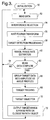
- FIGS 3-4 represent computer program instructions executed by the signal processor 36 of Figure 2 in carrying out the method of this invention.
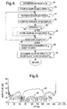
- Figure 3 describes the operation of signal processor 36 in general, while Figure 4 gives further detail in respect to the interference rejection of this invention.
- the block 50 designates initialization routine in which various parameters and variables used in the routine are initialized to predefined values and states.
- the processor 36 executes a series of processing steps identified by the blocks 52-60, including the interference rejection method of this invention (block 54) which are repeated for each beam position in a given scan, as indicated by the block 62 and return line 64.
- processing steps include reading the return data received by receiver 44 (block 52), performing the interference rejection method of this invention (block 54), performing a fast fourier transform on the received data to form frequency and amplitude data for each beam position (block 56), processing the amplitude data to detect any potential targets in the viewing angle (block 58), and estimating range and range-rate parameters of any identified targets based on the fast fourier transform frequency and amplitude data (block 60).
- the block 66 is executed to group the amplitude data into amplitude vs. azimuth angle profiles, categorizing contiguous return data into groups of similar range and range rate within a given tolerance or window.
- the blocks 68-72 are executed to perform target tracking based on the range, range rate, angle and angle extent of each of the identified targets determined in block 66, to select the closest in-path target, and to output its range and range-rate data to the system processor 38.
- the system processor 38 analyzes the target data to determine what, if any, vehicle response is appropriate, as explained above.
- block 80 is executed to store N data samples into the array A K , where K is the beam number.
- the first M successive samples from A K are identified in block 81.
- the variance of the M samples is calculated in block 82. If the variance S exceeds the threshold T S , as determined at block 83, the (i)th transient is declared and the current M samples are stored in a sub-array B i,K , as indicated at block 84.
- the next M samples are retrieved from array A K and the process is repeated until all N data samples in A K are processed.
- Each sub-array is then processed as indicated at blocks 88-90 to determine a bound for the sub-array samples, reset them to zero, determine the local slope of the A K array outside the determined bounds, and then substitute linearly interpolated data into the A K array.
- the interference rejection involves steps of transient recognition, excision, and restoration.
- Figure 5 depicts a data array after fast fourier transformation, where the data is subject to system-to-system interference, but no target is present.
- the noise level is very high, as indicated by the solid trace 94.
- the interference rejection method of this invention is enabled, the noise level is significantly reduced, as indicated by the broken trace 96.
- the high noise levels due to system-to-system interference can result in loss of target information, and increased likelihood of false alarms.
- targets can be more reliably identified and recognized.
- this invention provides a simple and cost effective method of rejecting system-to-system interference in a FLR system with only minimal distortion of the data corresponding to the energy reflected by legitimate scatterers in the field of vision. While this invention has been described in reference to the illustrated embodiment, it is expected that various modifications in addition to those suggested above will occur to those skilled in the art. For example, the method equally applies to both fixed and scanned systems, and both CW and FMCW or other systems.
Landscapes
- Engineering & Computer Science (AREA)
- Radar, Positioning & Navigation (AREA)
- Remote Sensing (AREA)
- Physics & Mathematics (AREA)
- Computer Networks & Wireless Communication (AREA)
- General Physics & Mathematics (AREA)
- Electromagnetism (AREA)
- Radar Systems Or Details Thereof (AREA)
Abstract
Description
The variance is defined in terms of the difference between the windowed samples (X1-XM) and the mean µ of the windowed samples. Specifically, the mean µ and variance S are defined as follows:
Claims (6)
- A method of interference rejection in a motor vehicle system having a forward looking radar sensor (34) that is subject to possible interference from other radar systems, the method comprising the steps of:successively sampling output data (52) of said radar sensor and storing the samples in a data array (80);computing a variance of said samples (82);associating said samples with a transient due to interference when the computed variance exceeds a threshold (83);bounding a subset of said array including said associated samples (88);creating a replacement set of data samples (90); andreplacing the bounded subset with the replacement set of data samples (90).
- The method of Claim 1, wherein N samples are stored in said data array (80), and the steps of sampling, computing and associating include the steps of:storing M successive samples in the data array, where M < N (81),computing a mean µ of the of said M samples (82);computing a variance S of said M samples from the computed mean µ (82); andassociating said M samples with a transient due to interference when the computed variance S of said M samples exceeds a threshold (83).
- The method of Claim 2, wherein the variance S is computed in accordance with the expression:
- The method of Claim 1, wherein the bounded subset of said array includes a predetermined number of data samples prior to and after said associated samples.
- The method of Claim 1, wherein the step of creating a replacement set of data samples includes the steps of:identifying first and second data samples taken respectively prior to and after said bounded subset of samples (88); andlinearly interpolating between said first and second data samples to create said replacement set of data samples (90).
- The method of Claim 5, including the steps of: determining a change in value between said first and second samples (90);computing a data slope based on a ratio of said determined change to a dimension of said bounded subset of samples (90); andcreating the replacement set of data by linear interpolation based on said computed data slope (90).
Applications Claiming Priority (2)
| Application Number | Priority Date | Filing Date | Title |
|---|---|---|---|
| US09/329,642 US6094160A (en) | 1999-06-10 | 1999-06-10 | Interference rejection method for an automotive radar CW/ICC system |
| US329642 | 1999-06-10 |
Publications (2)
| Publication Number | Publication Date |
|---|---|
| EP1059541A2 true EP1059541A2 (en) | 2000-12-13 |
| EP1059541A3 EP1059541A3 (en) | 2001-05-16 |
Family
ID=23286355
Family Applications (1)
| Application Number | Title | Priority Date | Filing Date |
|---|---|---|---|
| EP00201678A Withdrawn EP1059541A3 (en) | 1999-06-10 | 2000-05-11 | Interference rejection method for an automative radar CW/ICC system |
Country Status (2)
| Country | Link |
|---|---|
| US (1) | US6094160A (en) |
| EP (1) | EP1059541A3 (en) |
Cited By (5)
| Publication number | Priority date | Publication date | Assignee | Title |
|---|---|---|---|---|
| CN101159962B (en) * | 2007-10-29 | 2010-04-21 | 中国移动通信集团设计院有限公司 | Data processing method and device for continuous wave test for propagation model correction |
| GB2532524A (en) * | 2014-11-21 | 2016-05-25 | Dizic Co Ltd | Ranging method, ranging device, location device and location method |
| EP3037840A1 (en) * | 2014-12-23 | 2016-06-29 | Thales Holdings UK Plc | Wind turbine rejection in non-scanning radar |
| EP3676627A1 (en) * | 2017-08-29 | 2020-07-08 | Veoneer US, Inc. | Apparatus and method for rf interference avoidance in an automotive detection system |
| EP4549989A1 (en) * | 2023-10-30 | 2025-05-07 | GM Cruise Holdings LLC | Adc interference cancelation by temporal filter |
Families Citing this family (27)
| Publication number | Priority date | Publication date | Assignee | Title |
|---|---|---|---|---|
| US6828544B2 (en) * | 2002-06-12 | 2004-12-07 | Ford Global Technologies, Llc | Active night vision system for vehicles employing anti-blinding scheme |
| US6774367B2 (en) * | 2002-08-14 | 2004-08-10 | Ford Global Technologies, Llc | Active night vision system for vehicles employing anti-blinding scheme |
| JP4007498B2 (en) * | 2002-11-15 | 2007-11-14 | 三菱電機株式会社 | Automotive radar equipment |
| DE10261027A1 (en) * | 2002-12-24 | 2004-07-08 | Robert Bosch Gmbh | Angle-resolving antenna system |
| JP2005181193A (en) * | 2003-12-22 | 2005-07-07 | Tdk Corp | Pulse-wave radar apparatus |
| CN1321023C (en) * | 2004-07-08 | 2007-06-13 | 汕头大学 | Automobile intelligent anticollision system |
| US7403153B2 (en) * | 2004-12-15 | 2008-07-22 | Valeo Raytheon Systems, Inc. | System and method for reducing a radar interference signal |
| JP4747652B2 (en) * | 2005-04-15 | 2011-08-17 | 株式会社デンソー | FMCW radar |
| JPWO2006123499A1 (en) * | 2005-05-16 | 2008-12-25 | 株式会社村田製作所 | Radar |
| US8054217B2 (en) | 2006-10-26 | 2011-11-08 | Raytheon Company | Radar imaging system and method using gradient magnitude second moment spatial variance detection |
| US8212717B2 (en) * | 2006-10-26 | 2012-07-03 | Raytheon Company | Radar imaging system and method using second moment spatial variance |
| JP5121404B2 (en) * | 2006-11-15 | 2013-01-16 | パナソニック株式会社 | Semiconductor device for spread spectrum radar apparatus |
| US8022864B2 (en) * | 2007-11-08 | 2011-09-20 | The United States Of America As Represented By The Secretary Of Commerce | Detection of transient signals in doppler spectra |
| DE102011079615A1 (en) * | 2011-07-22 | 2013-01-24 | Robert Bosch Gmbh | FMCW radar system and interference detection method for FMCW radar systems |
| NO335171B1 (en) * | 2011-10-07 | 2014-10-13 | 3D Radar As | Adaptive interference suppression for georadar |
| DE102012021212A1 (en) | 2012-10-27 | 2014-04-30 | Valeo Schalter Und Sensoren Gmbh | Method for detecting interference in a received signal of a radar sensor, driver assistance device and motor vehicle |
| DE102012021240A1 (en) | 2012-10-27 | 2014-04-30 | Valeo Schalter Und Sensoren Gmbh | A method of suppressing interference in a received signal of a radar sensor of a motor vehicle and corresponding driver assistance means |
| DE102012021239A1 (en) * | 2012-10-27 | 2014-04-30 | Valeo Schalter Und Sensoren Gmbh | A method for detecting an interference in a received signal of a radar sensor, Fahrassistzeinrichtung and motor vehicle |
| DE102014203723A1 (en) * | 2014-02-28 | 2015-09-03 | Robert Bosch Gmbh | Method for operating mobile platforms |
| US9720072B2 (en) | 2014-08-28 | 2017-08-01 | Waymo Llc | Methods and systems for vehicle radar coordination and interference reduction |
| DE102014116165A1 (en) * | 2014-11-06 | 2016-05-12 | Valeo Schalter Und Sensoren Gmbh | Method for detecting an interference in a received signal of a radar sensor of a motor vehicle, computing device, driver assistance system, motor vehicle and computer program product |
| EP3173812B1 (en) * | 2015-11-24 | 2021-01-06 | Veoneer Sweden AB | A vehicle radar system arranged for reducing interference |
| DE102019101015A1 (en) * | 2018-01-17 | 2019-07-18 | Hirschmann Car Communication Gmbh | An offset from a receiving system LTE module |
| EP3637127B1 (en) | 2018-10-12 | 2024-11-27 | Axis AB | Method, device, and system for interference reduction in a frequency-modulated continuous-wave radar unit |
| US12397779B2 (en) | 2020-01-27 | 2025-08-26 | Ford Global Technologies, Llc | Detection of vehicle operating conditions |
| CN112285653B (en) * | 2020-10-14 | 2024-04-26 | 广州极飞科技股份有限公司 | Signal interference removal method, device, millimeter wave radar module, equipment and medium |
| JP7769586B2 (en) * | 2022-05-02 | 2025-11-13 | 株式会社デンソー | radar equipment |
Family Cites Families (10)
| Publication number | Priority date | Publication date | Assignee | Title |
|---|---|---|---|---|
| GB8407764D0 (en) * | 1984-03-26 | 1984-05-02 | Indep Broadcasting Authority | Local movement detector |
| DE3446529A1 (en) * | 1984-12-20 | 1986-07-03 | Blaupunkt-Werke Gmbh, 3200 Hildesheim | METHOD FOR REDUCING INTERFERENCE IN A BROADCAST RECEIVER |
| FR2686156A1 (en) * | 1985-10-09 | 1993-07-16 | Plessey Overseas | Receiving system |
| US5018215A (en) * | 1990-03-23 | 1991-05-21 | Honeywell Inc. | Knowledge and model based adaptive signal processor |
| JP2962158B2 (en) * | 1994-09-08 | 1999-10-12 | 三菱電機株式会社 | Radar signal processing equipment |
| SE503650C2 (en) * | 1994-11-10 | 1996-07-22 | Hans Hellsten | Ways to improve radar data on a radar |
| US5554955A (en) * | 1995-08-28 | 1996-09-10 | Myers; Glen A. | Method and apparatus for removing the effects of co-channel interference from the message on a dominant frequency modulated carrier and for recovering the message from each of two co-channel carriers |
| US5712628A (en) * | 1995-08-31 | 1998-01-27 | Northrop Grumman Corporation | Digitally programmable radio modules for transponder systems |
| US6011507A (en) * | 1996-11-12 | 2000-01-04 | Raytheon Company | Radar system and method of operating same |
| NL1005067C2 (en) * | 1997-01-23 | 1998-07-27 | Hollandse Signaalapparaten Bv | Radar device. |
-
1999
- 1999-06-10 US US09/329,642 patent/US6094160A/en not_active Expired - Lifetime
-
2000
- 2000-05-11 EP EP00201678A patent/EP1059541A3/en not_active Withdrawn
Cited By (7)
| Publication number | Priority date | Publication date | Assignee | Title |
|---|---|---|---|---|
| CN101159962B (en) * | 2007-10-29 | 2010-04-21 | 中国移动通信集团设计院有限公司 | Data processing method and device for continuous wave test for propagation model correction |
| GB2532524A (en) * | 2014-11-21 | 2016-05-25 | Dizic Co Ltd | Ranging method, ranging device, location device and location method |
| GB2532524B (en) * | 2014-11-21 | 2017-03-22 | Dizic Co Ltd | Ranging method, ranging device, location device and location method |
| EP3037840A1 (en) * | 2014-12-23 | 2016-06-29 | Thales Holdings UK Plc | Wind turbine rejection in non-scanning radar |
| US10502822B2 (en) | 2014-12-23 | 2019-12-10 | Thales Holdings Uk Plc | Wind turbine rejection in non-scanning radar |
| EP3676627A1 (en) * | 2017-08-29 | 2020-07-08 | Veoneer US, Inc. | Apparatus and method for rf interference avoidance in an automotive detection system |
| EP4549989A1 (en) * | 2023-10-30 | 2025-05-07 | GM Cruise Holdings LLC | Adc interference cancelation by temporal filter |
Also Published As
| Publication number | Publication date |
|---|---|
| EP1059541A3 (en) | 2001-05-16 |
| US6094160A (en) | 2000-07-25 |
Similar Documents
| Publication | Publication Date | Title |
|---|---|---|
| US6094160A (en) | Interference rejection method for an automotive radar CW/ICC system | |
| US11313943B2 (en) | Vehicle radar system arranged for reducing interference | |
| EP1672379B1 (en) | System and method for reducing a radar interference signal | |
| EP2097769B1 (en) | System and method for reducing the effect of a radar interference signal | |
| JP2642294B2 (en) | Distance measurement, detection and resolution method for multi-slope frequency modulated waveform radar system | |
| EP2317334B1 (en) | Method and program for displaying radar image, and target object detection signal processing device | |
| US5430450A (en) | Method and apparatus for automatically dimming motor vehicle headlights using radar signal | |
| US6833807B2 (en) | Method for adaptive target processing in a motor vehicle radar system | |
| US7489265B2 (en) | Vehicle sensor system and process | |
| EP0899582A2 (en) | Motor vehicle object detection method | |
| US20100109938A1 (en) | Adaptive radar | |
| US8305261B2 (en) | Adaptive mainlobe clutter method for range-Doppler maps | |
| JP7173735B2 (en) | Radar device and signal processing method | |
| JP4668198B2 (en) | Radar equipment | |
| CN110632587A (en) | Weak moving object monitoring method based on rapid FMCW radar | |
| CN106908794A (en) | Method and apparatus for detecting target object | |
| US20220404455A1 (en) | Radar Interference Mitigation Using Signal Pattern Matching | |
| US7379018B1 (en) | System and method for verifying a radar detection | |
| CN110907930B (en) | Vehicle-mounted radar target detection and estimation method and device based on angle estimation | |
| CN113325421A (en) | Method and computer-readable medium for providing the at least one target information | |
| CN1063268C (en) | Radar apparatus | |
| Lane | The effects of Doppler and pulse eclipsing on sidelobe reduction techniques | |
| CN111157954A (en) | Adaptive Adjustment Method of Ground Radar Target Detection Threshold Coefficient | |
| KR102968599B1 (en) | Method for enhancing radar range-doppler data resolution using high-resolution range profiles | |
| Khatri et al. | Influence of a strong radar reflector in the scene on the image formed by synthetic aperture radar using backprojection algorithm |
Legal Events
| Date | Code | Title | Description |
|---|---|---|---|
| PUAI | Public reference made under article 153(3) epc to a published international application that has entered the european phase |
Free format text: ORIGINAL CODE: 0009012 |
|
| AK | Designated contracting states |
Kind code of ref document: A2 Designated state(s): DE FR GB IT |
|
| AX | Request for extension of the european patent |
Free format text: AL;LT;LV;MK;RO;SI |
|
| PUAL | Search report despatched |
Free format text: ORIGINAL CODE: 0009013 |
|
| AK | Designated contracting states |
Kind code of ref document: A3 Designated state(s): AT BE CH CY DE DK ES FI FR GB GR IE IT LI LU MC NL PT SE |
|
| AX | Request for extension of the european patent |
Free format text: AL;LT;LV;MK;RO;SI |
|
| 17P | Request for examination filed |
Effective date: 20011116 |
|
| AKX | Designation fees paid |
Free format text: DE FR GB IT |
|
| 17Q | First examination report despatched |
Effective date: 20021114 |
|
| STAA | Information on the status of an ep patent application or granted ep patent |
Free format text: STATUS: THE APPLICATION IS DEEMED TO BE WITHDRAWN |
|
| 18D | Application deemed to be withdrawn |
Effective date: 20030325 |