EP1059521A2 - System and method for continuous monitoring of particulates - Google Patents
System and method for continuous monitoring of particulates Download PDFInfo
- Publication number
- EP1059521A2 EP1059521A2 EP00304827A EP00304827A EP1059521A2 EP 1059521 A2 EP1059521 A2 EP 1059521A2 EP 00304827 A EP00304827 A EP 00304827A EP 00304827 A EP00304827 A EP 00304827A EP 1059521 A2 EP1059521 A2 EP 1059521A2
- Authority
- EP
- European Patent Office
- Prior art keywords
- membrane
- particulates
- collected
- mass
- oscillatory movement
- Prior art date
- Legal status (The legal status is an assumption and is not a legal conclusion. Google has not performed a legal analysis and makes no representation as to the accuracy of the status listed.)
- Withdrawn
Links
Images


Classifications
-
- G—PHYSICS
- G01—MEASURING; TESTING
- G01N—INVESTIGATING OR ANALYSING MATERIALS BY DETERMINING THEIR CHEMICAL OR PHYSICAL PROPERTIES
- G01N15/00—Investigating characteristics of particles; Investigating permeability, pore-volume or surface-area of porous materials
- G01N15/06—Investigating concentration of particle suspensions
- G01N15/0606—Investigating concentration of particle suspensions by collecting particles on a support
- G01N15/0618—Investigating concentration of particle suspensions by collecting particles on a support of the filter type
-
- G—PHYSICS
- G01—MEASURING; TESTING
- G01G—WEIGHING
- G01G3/00—Weighing apparatus characterised by the use of elastically-deformable members, e.g. spring balances
- G01G3/12—Weighing apparatus characterised by the use of elastically-deformable members, e.g. spring balances wherein the weighing element is in the form of a solid body stressed by pressure or tension during weighing
- G01G3/16—Weighing apparatus characterised by the use of elastically-deformable members, e.g. spring balances wherein the weighing element is in the form of a solid body stressed by pressure or tension during weighing measuring variations of frequency of oscillations of the body
-
- G—PHYSICS
- G01—MEASURING; TESTING
- G01N—INVESTIGATING OR ANALYSING MATERIALS BY DETERMINING THEIR CHEMICAL OR PHYSICAL PROPERTIES
- G01N1/00—Sampling; Preparing specimens for investigation
- G01N1/02—Devices for withdrawing samples
- G01N1/22—Devices for withdrawing samples in the gaseous state
- G01N1/2247—Sampling from a flowing stream of gas
- G01N1/2258—Sampling from a flowing stream of gas in a stack or chimney
Definitions
- the present invention relates generally to a system and method for measuring and monitoring the mass concentration of airborne particles, especially in fixed point source emission environments (e. g., stack effluent streams).
- fixed point source emission environments e. g., stack effluent streams.
- Technique (a) requires a radioactive source (the latter presenting more of a problem with public perception than system performance), but more importantly, it often suffers from excessive probe losses associated with the need for sample extraction from the stack environment.
- Techniques (b) and (c) have the advantage of being in situ detectors, which do not exhibit significant probe losses. However, they are not based on true mass sensing, instead being based on surrogate principles, which are influenced by particle properties, and which require process and/or site specific gravimetric calibration.
- U.S. Patent No. 5,349,844 describes a system and method that uses a taut filter membrane to collect airborne particulate.
- the filter is then oscillated by an acoustical or electrical device, for example, so that it can resonate at a natural frequency.
- the mass concentration of the airborne particulates may then be computed from the resonant frequency.
- the present invention consists of a system for, and method of, accurately monitoring airborne particulates.
- Preferred embodiments of the present invention include a membrane and an electrostatic precipitator disposed in spaced relation to one surface of the membrane.
- An activation circuit causes the electrostatic precipitator to create an ionizing volume in which particulates are electrically charged.
- the charged particulates are collected on the membrane, and an actuation circuit causes oscillatory movement of the membrane.
- a detector detects the oscillatory movement of the membrane, which is indicative of an amount of particulate matter collected on the membrane.
- the membrane surface is substantially parallel to the direction of air flow in a housing receiving the airflow.
- the membrane is conductive and the system further includes an electrode positioned on an opposite side of the one surface of the membrane so as to form a capacitor with the membrane.
- the detector may determine oscillations through a capacitance measurement.
- the actuation circuit causes the membrane to oscillate at a resonance frequency of the membrane with the particulates collected thereon, the resonance frequency being indicative of a mass increment of the membrane due to the collected particulates.
- the system may include a removable and replaceable frame for holding the membrane.
- a housing is provided to contain the membrane and the corona wire, together forming an electrostatic precipitator.
- the activation circuit and the actuation circuit are positioned remote from the housing.
- the housing may be placed in a monitoring environment, such as a stack, whereas the circuitry may be placed in a less hostile environment.
- a mass increment of the membrane having the particulates collected thereon may be calculated in comparison to a predetermined mass, such as a tare mass of the membrane.
- the mass concentration of particulates may be determined by determining the rate of airflow and by the mass increment.
- a preferred embodiment of the invention uses electrostatic precipitation to cause airborne particulates to be collected on a membrane.
- the mass increment of the collected particulate matter is then detected by resonant oscillation of that membrane, e.g., transverse oscillation, and the mass concentration may be determined by also determining the rate of airflow.
- the mass increment By detecting the mass increment the particulates may be continuously monitored, and the system does not need to replace or clean components after each measurement.
- FIG 1 depicts a preferred embodiment of the invention.
- the system 1 includes a housing 2 having an inlet 4 and an outlet 5.
- the housing 2 contains a frame 6 which holds a metal membrane 8, positioned below a corona discharge wire 10 and above a plate electrode 12.
- the membrane 8 and electrode 12 together form a capacitor 13.
- Figure 2 depicts the precipitator elements 10 and 8 in electrical communication with an activation circuit 14, and the membrane 8 and electrode 12 are in electrical communication with an actuation and sensing circuit 16.
- Housing 2 is preferably constructed of an electrically insulating material, e.g., ceramic/composite, capable of withstanding temperatures of up to several hundred degrees Celsius.
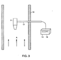
- the housing 2 may be attached to a supporting/locating wand 17 (typically made of stainless steel) as shown in Figure 3 so that the arrangement may be inserted into a stack 18 to attain the proper orientation,
- the circuits 14, 16 may be positioned outside of the stack, but in communication with the sensor/collector apparatus as described below.
- Housing 2 has an inlet 4 that is positioned to be open to the flow of air, shown by the arrow A, and an outlet 5 from which the air exits. Because the orientation of the surface of the membrane 8 is parallel to the air flow, the tension of the membrane 8 should not be affected thereby.
- the system 1 has low air resistance and isokinetic conditions are very nearly maintained over a wide range of stream velocities.
- This design though not critical to operation, obviates the requirements for a pump and isokinetic control elements.
- the transition from the inlet 4 to the housing's interior is designed as a divergent channel (for example, as shown) to reduce flow velocity in the interior, where the particulates are collected and sensed. This design facilitates the collection of particulates at high stack flow velocities.
- a frame 6 is fixed to the housing 2 (e.g., by sliding it into slots on the interior walls of housing 2) and holds a metal membrane 8 taut.
- the membrane is attached under tension to the metal frame and affixed to that frame either by welding or by means of an adhesive (e.g., high temperature epoxy).
- Preferred embodiments use an appropriately thin foil type for membrane 8, e.g., stainless steel of around 0.0001 to 0.0005 inch thickness.
- Typical area of the collection/oscillating foil is of the order of 20 to 200 square centimeters.
- a frame 6 and membrane 8 are selected so that expansion coefficients match.
- Other approaches may be used as supplements or substitutes to the above, such as compensating the calculations (discussed below) based on a measured temperature, or allowing sufficient warm up time until the sensor arrangement has reached a thermal equilibrium within the relatively stable thermal environment of the stack.
- a corona wire 10 is used as one of the two electrodes of the electrostatic precipitator.
- Corona wire 10 is positioned on one side of and parallel to the membrane 8 and extends longitudinally in the direction of the flow A. In other embodiments the corona wire 10 may be positioned differently, e.g., perpendicular to the flow or at other angles.
- the corona wire is supported under tension by conventional attachments (not shown) to the insulating body 2.
- the corona wire 10 is in electrical communication with activation circuit 14, which applies a potential difference between the corona wire 10 and the upper surface of the taut membrane 8, creating a surrounding electrical field which ionizes the air molecules and, in turn, electrically charges the particulates passing through the interior of the housing.
- the applied potential within the electrostatic precipitator is of the direct current (d.c.) type wherein the corona wire may be either at a positive or a negative potential with respect to the taut foil collecting electrode.
- a positive corona wire (which generates positive ions) is preferred for this application because it generates a more uniform flow of ions than a negatively charged corona wire.
- the typical range of distances between the corona wire 10 and the collecting foil electrode 8 is 2 to 10 centimeters, and typical potential differences (i.e., applied voltage) are of the order of 5,000 to 15,000 volts, depending on inter-electrode distance and whether the corona wire is positive or negative with respect to the collecting electrode.
- the rigid metal plate electrode 12 is located on an opposite side of the membrane 8.
- the plate 12 may be placed about 1 mm or less from the membrane 8, thus forming parallel plate capacitor 13. This rigid place may be as large or smaller in area than the taut foil membrane 8, and is permanently affixed to the interior of the housing 2, and not exposed to the particle laden air stream.
- Actuation and sensing circuit 16 includes a variable frequency sine wave generator 18 connected to plate 12 and membrane 8.
- Circuit 16 also includes a capacitance detection circuit 20 connected to plate 12 and membrane 8. Suitable forms of such detection circuits are well known in the art (e.g., impedance sensing circuitry, etc.). The sine wave generator and capacitance detection circuit cooperate as described below.
- the resonance condition of the membrane i.e., maximum oscillatory displacement
- other means such as acoustic or optical techniques.
- the housing 2 is placed in situ as described above. Once so placed, a particle laden stream flows into the inlet 4 and passes through an ionizing volume (see region bounded by dashed lines of Figure 2) of the electrostatic precipitator where the particles are charged. The charged particles are electrically attracted to membrane 8 because it is at a potential of opposite sign than the particle charge.
- the collection/oscillation membrane 8 serves as an electrically common element between the electrostatic precipitator, on one of its sides, and as a capacitive detector 12, on the other. Electrically, the membrane 8 is at ground potential with respect to the corona wire which is at a high d.c. potential, and with respect to the rigid plate electrode of the capacitive detection configuration on its opposite side.
- variable frequency sine wave generator 18 Prior to and at the completion of a particle collection period (whose duration is in the typical range of minutes) the variable frequency sine wave generator 18 is caused to apply an alternating potential across the capacitor 13. This potential in turn should cause a minute oscillating deflection of the taut membrane 8.
- the capacitance detection circuit 20 senses the synchronously varying capacitance resulting from the deflection of the membrane 8. Closed-loop feedback or analogous control is used to monitor the detected capacitance and to control the sine wave generator 18 in response to tune the generator to the frequency at which the modulation of the capacitance maximizes. That frequency is the natural resonance of the taut membrane 8 with the particulates collected thereon.
- ⁇ m m 0 [f 0 /f 1 ) 2 - 1]
- ⁇ m the particulate mass increment just collected on the membrane (i.e., the most recent particulate sample)
- m 0 is the initial or tare mass of the membrane
- f 0 and f 1 are the initial and final resonance frequencies of the oscillating membrane, respectively, i.e., the resonance frequency when m 0 is measured and when later measurement is made to determine ⁇ m.
- the detection of the resonance frequency could be performed continuously during the collection period, in which case the mass of the collected particulate matter is computed continuously from the change of resonance frequency.
- the system will not require calibration, i.e., it constitutes a primary measurement method. It should be understood that the actual or absolute value of the capacitance between the membrane 8 and fixed plate electrode 12 is immaterial to the mass measurement; only the degree of variability of this capacitance as a function of frequency is used to determine the membrane resonance frequency.
- the flow rate through the sensor must be known in addition to the mass increment per unit time.
- This flow rate is the product of the inlet 4 cross sectional area and the stack effluent velocity directly upstream of the inlet, a parameter which needs to be known or measured typically by means of a pitot-tube. This assumes that the mass sensor unit presents negligible flow resistance at the stack gas velocity, a reasonable assumption given that the sensor is essentially wide open.
- this force should result in a membrane deflection of the order of 10 ⁇ m, i.e., for this case, and in the absence of resonance, a 200-V peak-to-peak sine wave would cause a membrane oscillation with an amplitude of about ⁇ 10 ⁇ m which, in turn, would produce a ⁇ 5% modulation of the capacitance.
- the amplitude of the membrane deflection would be many times larger (typically more than 10 times), thus producing a corresponding larger modulation of the membrane-to-plate capacitance.
- a new measurement can be initiated with an already soiled membrane, since the measurement of mass is based on sensing its increment as a function of time.
- the membrane need not be replaced or cleaned after each measurement, and continuous monitoring may be achieved.
- the metal membrane 8 may in time get coated too thickly with particles and thus require replacement.
- the membrane 8, mounted (pre-tensioned) on a frame 6, may be arranged as a replaceable "cassette.”
- the cassette may be removed when needed and may be cleaned using ultrasonication, for example, after which it may be re-used.
- a control circuit could calculate the total amount of mass collected on a membrane and a threshold value may be set to indicate when a cassette (or membrane) needs to be replaced (or cleaned). This could be reset to zero on the control unit every time the cassette is replaced.
- the taut membrane 8 described above need not vibrate at its lowest resonance frequency (the fundamental mode), but may instead oscillate at higher resonant modes for the measurement of accumulated mass. Operation at a higher resonance mode provides enhanced sensitivity and improved stability.
- the two electrodes forming the parallel plate capacitor may be of differing size and or shape, in order to optimize mass sensing.
- the fixed plate electrode 12 may be preferably of smaller area than the membrane 8, in order to sense the deflection of a specific section of the membrane.
- the deflection of the membrane 8 may be detected with optical and other known techniques, as mentioned above.
- the above embodiments may be used to continuously monitor particulates in potentially hostile and extreme environments (e.g., high temperature, corrosive gases, high moisture content).
- the construction of the system is simple and should be realizable at lower cost in comparison to other continuous monitoring systems. Reliability should be higher than other devices that require components with moving parts, such as pumps, blowers, valves, etc.
- this invention although especially suited for in-stack emission monitoring applications, is not limited to such uses, but could be designed for monitoring ambient (extramural) air, or for indoor air quality measurements.
- an air mover such as a pump or blower would be required to ensure a sampling flow through the collection/detection chamber.
- air motion could be induced by means of the ion wind concomitant with the corona electric discharge generated by the electrostatic precipitator incorporated in this invention.
Landscapes
- Physics & Mathematics (AREA)
- General Physics & Mathematics (AREA)
- Chemical & Material Sciences (AREA)
- Dispersion Chemistry (AREA)
- Health & Medical Sciences (AREA)
- Life Sciences & Earth Sciences (AREA)
- Analytical Chemistry (AREA)
- Biochemistry (AREA)
- General Health & Medical Sciences (AREA)
- Immunology (AREA)
- Pathology (AREA)
- Other Investigation Or Analysis Of Materials By Electrical Means (AREA)
- Electrostatic Separation (AREA)
Abstract
Description
Claims (15)
- A system for monitoring airborne particulates comprising:a membrane;an electrostatic precipitator disposed in spaced relation to one surface of the membrane;an activation circuit in electrical communication with the electrostatic precipitator causing the precipitator to create an ionizing volume to electrically charge the particulates therein and so that the charged particulates are collected on the membrane;an actuation circuit in electrical communication with the membrane to cause oscillatory movement of the membrane; anda detector in communication with the membrane to detect the oscillatory movement of the membrane, such that the oscillatory movement is indicative of an mass increment amount of particulates collected on the membrane.
- The system of claim 1 further comprising a housing having an inlet for receiving an airflow and wherein the one membrane surface is substantially parallel to the direction of air flow in the housing.
- The system of claim 1 wherein the membrane is conductive and further comprising an electrode positioned on an opposite side of the one surface of the membrane so as to form a capacitor with the membrane, and wherein the detector includes a capacitance detection circuit in electrical communication with the capacitor to detect capacitance variations caused by the oscillatory movement of the membrane.
- The system of claim 1 wherein the actuation circuit causes the membrane to oscillate at a resonance frequency of the membrane and of particulates collected thereon.
- The system of claim 3 wherein the actuation circuit and the capacitance detection circuit cooperate so that the actuation circuit is caused to actuate the membrane at a resonance frequency of the membrane and of particulates collected thereon.
- The system of claim 5 further comprising a removable and replaceable frame for holding the membrane.
- The system of claim 1 wherein the electrostatic precipitator is a corona wire and taut membrane combination.
- The system of claim 1 further comprising a housing containing the membrane and the electrostatic precipitator, and wherein the activation circuit and the actuation circuit are positioned remote from the housing.
- A method of monitoring airborne particulates, comprising the steps of:(a) receiving an airflow containing particulates along a direction in predetermined relation to a membrane;(b) inducing electrostatic precipitation to cause particulates in the airflow to ionize and to collect on the membrane;(c) oscillating the membrane having the particulates collected thereon;(d) detecting the oscillations of the membrane;(e) calculating a mass increment of the membrane having the particulates collected thereon in comparison to a predetermined mass.
- The method of claim 9 wherein the membrane is positioned to be substantially parallel to the direction of airflow.
- The method of claim 9 wherein step (c) operates in response to step (d) in a controlled manner to cause the membrane having particulates collected thereon to oscillate at a resonance frequency.
- The method of claim 9 wherein step (d) detects the oscillations through a capacitive measurement.
- The method of claim 11 wherein step (e) calculates the mass increment in comparison to the rare mass of the membrane.
- The method of claim 9 further comprising the steps of determining the rate of airflow and calculating the mass concentration of particulates from the rate of airflow and the mass increment per unit time.
- A system for monitoring airborne particulate, comprising:an electrically insulating housing defining an inlet and an outlet through which air may flow;a metal membrane disposed within the housing with the membrane surface parallel to air flowing between the inlet and outlet;a corona wire disposed within the housing and in spaced relation to one surface of the membrane forming an electrostatic precipitator;an activation circuit in electrical communication with the electrostatic precipitator causing the precipitator to create an ionizing volume to ionize particulates therein and so that the ionized particulates are collected on the membrane;an actuation circuit in electrical communication with the membrane to cause oscillatory movement of the membrane; anda detector in communication with the membrane and cooperating with the actuation circuit to detect the oscillatory movement of the membrane and to cause the membrane to oscillate at resonant frequency, such that the oscillatory movement is indicative of an mass increment amount of particulates collected on the membrane.
Applications Claiming Priority (2)
| Application Number | Priority Date | Filing Date | Title |
|---|---|---|---|
| US32693699A | 1999-06-07 | 1999-06-07 | |
| US326936 | 1999-06-07 |
Publications (2)
| Publication Number | Publication Date |
|---|---|
| EP1059521A2 true EP1059521A2 (en) | 2000-12-13 |
| EP1059521A3 EP1059521A3 (en) | 2003-05-21 |
Family
ID=23274411
Family Applications (1)
| Application Number | Title | Priority Date | Filing Date |
|---|---|---|---|
| EP00304827A Withdrawn EP1059521A3 (en) | 1999-06-07 | 2000-06-07 | System and method for continuous monitoring of particulates |
Country Status (1)
| Country | Link |
|---|---|
| EP (1) | EP1059521A3 (en) |
Cited By (10)
| Publication number | Priority date | Publication date | Assignee | Title |
|---|---|---|---|---|
| EP1251344A3 (en) * | 2001-04-18 | 2003-11-12 | AVL List GmbH | Process for measuring aerosol particles in gas samples |
| US7197911B1 (en) * | 2004-04-29 | 2007-04-03 | Thermo Electron Corporation | Methods and apparatus for mechanical resonance monitoring a mass concentration of particulate matter |
| WO2009141515A1 (en) * | 2008-05-20 | 2009-11-26 | Commissariat A L'energie Atomique | Device for the gravimetric detection of particles in a fluid medium, comprising an oscillator between two fluid channels, production process and method of employing the device |
| WO2009141516A1 (en) * | 2008-05-20 | 2009-11-26 | Commissariat A L'energie Atomique | Device for the gravimetric detection of particles in a fluid medium, comprising an oscillator over which a fluid stream flows, production process and method of employing the device |
| WO2010060905A1 (en) * | 2008-11-26 | 2010-06-03 | Eads Deutschland Gmbh | Device for collecting particles that have a strong electron affinity |
| CN101887003A (en) * | 2010-06-29 | 2010-11-17 | 上海杰远环保科技有限公司 | A particle measuring device and its measuring method |
| DE102013001163B3 (en) * | 2013-01-24 | 2014-04-30 | Chemin Gmbh | Grid probe for measuring deposit-forming components in gas streams in boilers of incinerators, has probe body, which is designed as pipe, where pipe has device for heating or cooling interior of grid probe or grid |
| CN105547931A (en) * | 2015-11-20 | 2016-05-04 | 武汉科技大学 | Corona electric field conductor particle oscillation amplitude detector and detection method thereof |
| CN106769739A (en) * | 2017-01-19 | 2017-05-31 | 兰州大学 | A kind of system for determining haze charged particle percentage |
| CN113728219A (en) * | 2018-08-30 | 2021-11-30 | 科学和技术中心 | Fine particle sensor with in-line microbalances |
Family Cites Families (3)
| Publication number | Priority date | Publication date | Assignee | Title |
|---|---|---|---|---|
| US3561253A (en) * | 1969-03-26 | 1971-02-09 | Thermo Systems Inc | Apparatus and method of measurement of particulate mass |
| JPH08500431A (en) * | 1992-04-30 | 1996-01-16 | フラウンホッファー−ゲゼルシャフト ツァ フェルダールング デァ アンゲヴァンテン フォアシュンク エー.ファオ. | High sensitivity sensor |
| GB9523812D0 (en) * | 1995-11-21 | 1996-01-24 | Sun Electric Uk Ltd | Method and apparatus for analysis of particulate content of gases |
-
2000
- 2000-06-07 EP EP00304827A patent/EP1059521A3/en not_active Withdrawn
Cited By (18)
| Publication number | Priority date | Publication date | Assignee | Title |
|---|---|---|---|---|
| EP1251344A3 (en) * | 2001-04-18 | 2003-11-12 | AVL List GmbH | Process for measuring aerosol particles in gas samples |
| US7197911B1 (en) * | 2004-04-29 | 2007-04-03 | Thermo Electron Corporation | Methods and apparatus for mechanical resonance monitoring a mass concentration of particulate matter |
| WO2009141515A1 (en) * | 2008-05-20 | 2009-11-26 | Commissariat A L'energie Atomique | Device for the gravimetric detection of particles in a fluid medium, comprising an oscillator between two fluid channels, production process and method of employing the device |
| WO2009141516A1 (en) * | 2008-05-20 | 2009-11-26 | Commissariat A L'energie Atomique | Device for the gravimetric detection of particles in a fluid medium, comprising an oscillator over which a fluid stream flows, production process and method of employing the device |
| FR2931550A1 (en) * | 2008-05-20 | 2009-11-27 | Commissariat Energie Atomique | DEVICE FOR THE GRAVIMETRIC DETECTION OF PARTICLES IN A FLUID MEDIA COMPRISING AN OSCILLATOR BETWEEN TWO FLUIDIC CHANNELS, A METHOD FOR PRODUCING THE SAME, AND METHOD FOR THE IMPLEMENTATION OF THE DEVICE |
| FR2931549A1 (en) * | 2008-05-20 | 2009-11-27 | Commissariat Energie Atomique | DEVICE FOR THE GRAVIMETRIC DETECTION OF PARTICLES IN A FLUID ENVIRONMENT, COMPRISING AN OSCILLATOR CROSSED BY A FLUIDIC VEIN, METHOD FOR PRODUCING THE SAME AND METHOD FOR IMPLEMENTING THE DEVICE |
| US8746048B2 (en) | 2008-05-20 | 2014-06-10 | Commissariat A L'energie Atomique Et Aux Energies Alternatives | Device for the gravimetric detection of particles in a fluid medium, comprising an oscillator between two fluid channels |
| US8844340B2 (en) | 2008-05-20 | 2014-09-30 | Commissariat a l'Energie et aux Energies Alternatives | Device for the gravimetric detection of particles in a fluid medium, comprising an oscillator over which a fluid stream flows, production process and method of employing the device |
| WO2010060905A1 (en) * | 2008-11-26 | 2010-06-03 | Eads Deutschland Gmbh | Device for collecting particles that have a strong electron affinity |
| US8852325B2 (en) | 2008-11-26 | 2014-10-07 | Eads Deutschland Gmbh | Device for collecting particles that have a strong electron affinity |
| CN101887003B (en) * | 2010-06-29 | 2016-06-08 | 上海杰远环保科技有限公司 | A kind of microparticle measuring device and measuring method thereof |
| CN101887003A (en) * | 2010-06-29 | 2010-11-17 | 上海杰远环保科技有限公司 | A particle measuring device and its measuring method |
| DE102013001163B3 (en) * | 2013-01-24 | 2014-04-30 | Chemin Gmbh | Grid probe for measuring deposit-forming components in gas streams in boilers of incinerators, has probe body, which is designed as pipe, where pipe has device for heating or cooling interior of grid probe or grid |
| CN105547931A (en) * | 2015-11-20 | 2016-05-04 | 武汉科技大学 | Corona electric field conductor particle oscillation amplitude detector and detection method thereof |
| CN106769739A (en) * | 2017-01-19 | 2017-05-31 | 兰州大学 | A kind of system for determining haze charged particle percentage |
| CN106769739B (en) * | 2017-01-19 | 2024-01-23 | 兰州大学 | A system for determining the percentage of charged particles in haze |
| CN113728219A (en) * | 2018-08-30 | 2021-11-30 | 科学和技术中心 | Fine particle sensor with in-line microbalances |
| CN113728219B (en) * | 2018-08-30 | 2024-05-24 | 科学和技术中心 | Fine particle sensor with in-line microbalance |
Also Published As
| Publication number | Publication date |
|---|---|
| EP1059521A3 (en) | 2003-05-21 |
Similar Documents
| Publication | Publication Date | Title |
|---|---|---|
| US7197911B1 (en) | Methods and apparatus for mechanical resonance monitoring a mass concentration of particulate matter | |
| US5349844A (en) | System and method for resonant filter mass monitoring | |
| US3561253A (en) | Apparatus and method of measurement of particulate mass | |
| US5214386A (en) | Apparatus and method for measuring particles in polydispersed systems and particle concentrations of monodispersed aerosols | |
| US5910700A (en) | Dust sensor apparatus | |
| JP4330307B2 (en) | Method for measuring aerosol particles in gaseous samples | |
| EP1059521A2 (en) | System and method for continuous monitoring of particulates | |
| JPH0145569B2 (en) | ||
| JP6454733B2 (en) | Aerosol particle mass sensor and sensing method | |
| JPH11502303A (en) | Method and apparatus for measuring particulate matter in gas | |
| WO2012022843A1 (en) | Particle sensor | |
| US20030089159A1 (en) | Method and apparatus for detecting particles in a gas flow | |
| JPH0743283A (en) | Mass concentration measuring method of dust particle in gas | |
| Sem et al. | A new mass sensor for respirable dust measurement | |
| EP1495316B1 (en) | Paramagnetic oxygen sensing apparatus and method | |
| Olin et al. | Piezoelectric-electrostatic aerosol mass concentration monitor | |
| GB2371362A (en) | Monitoring apparatus and method for detecting particles in a gas stream using ionisation means and a SAW detector | |
| CN101680857B (en) | Ion mobility spectrometer including spaced electrodes for filterin | |
| EP0062432B1 (en) | Vibrating vane pressure gauge | |
| CN104390891B (en) | A kind of portable PM2.5 detector of improvement | |
| JP5862202B2 (en) | Suspended particulate matter measuring apparatus and suspended particulate matter measuring method | |
| JPH0830673B2 (en) | How to measure the mass concentration of dust particles | |
| Brown et al. | Theory and measurement of the capture of charged dust particles by electrets | |
| JPH01180258A (en) | Dust concentration detector and air cleaner provided with said detector | |
| WO2005069904A2 (en) | Microfabricated device for selectively removing and analyzing airborne particulates |
Legal Events
| Date | Code | Title | Description |
|---|---|---|---|
| PUAI | Public reference made under article 153(3) epc to a published international application that has entered the european phase |
Free format text: ORIGINAL CODE: 0009012 |
|
| AK | Designated contracting states |
Kind code of ref document: A2 Designated state(s): AT BE CH CY DE DK ES FI FR GB GR IE IT LI LU MC NL PT SE |
|
| AX | Request for extension of the european patent |
Free format text: AL;LT;LV;MK;RO;SI |
|
| PUAL | Search report despatched |
Free format text: ORIGINAL CODE: 0009013 |
|
| AK | Designated contracting states |
Designated state(s): AT BE CH CY DE DK ES FI FR GB GR IE IT LI LU MC NL PT SE |
|
| AX | Request for extension of the european patent |
Extension state: AL LT LV MK RO SI |
|
| AKX | Designation fees paid | ||
| REG | Reference to a national code |
Ref country code: DE Ref legal event code: 8566 |
|
| STAA | Information on the status of an ep patent application or granted ep patent |
Free format text: STATUS: THE APPLICATION IS DEEMED TO BE WITHDRAWN |
|
| 18D | Application deemed to be withdrawn |
Effective date: 20031122 |