EP1059507A1 - Kalibrationseinrichtung für optoelektronische Sensorsysteme - Google Patents
Kalibrationseinrichtung für optoelektronische Sensorsysteme Download PDFInfo
- Publication number
- EP1059507A1 EP1059507A1 EP00250155A EP00250155A EP1059507A1 EP 1059507 A1 EP1059507 A1 EP 1059507A1 EP 00250155 A EP00250155 A EP 00250155A EP 00250155 A EP00250155 A EP 00250155A EP 1059507 A1 EP1059507 A1 EP 1059507A1
- Authority
- EP
- European Patent Office
- Prior art keywords
- calibration device
- orientation parameters
- reference module
- ccd
- light
- Prior art date
- Legal status (The legal status is an assumption and is not a legal conclusion. Google has not performed a legal analysis and makes no representation as to the accuracy of the status listed.)
- Granted
Links
Images
Classifications
-
- G—PHYSICS
- G01—MEASURING; TESTING
- G01C—MEASURING DISTANCES, LEVELS OR BEARINGS; SURVEYING; NAVIGATION; GYROSCOPIC INSTRUMENTS; PHOTOGRAMMETRY OR VIDEOGRAMMETRY
- G01C11/00—Photogrammetry or videogrammetry, e.g. stereogrammetry; Photographic surveying
- G01C11/02—Picture taking arrangements specially adapted for photogrammetry or photographic surveying, e.g. controlling overlapping of pictures
Definitions
- the invention relates to a calibration device for the orientation parameters of digital optoelectronic sensor systems in carrier systems for Remote sensing.
- the orientation parameters are generally included Help determined by control points in the course of image evaluation. The coordinates these control points are well measured. The determination of the Orientation in recent years through the use of GPS and navigation systems.
- Such a parameter determination is for example from DE 38 02 219 A1 is known, with one or more line scanners associated with optoelectronic, areal camera or one Combination of such cameras at regular intervals a series of overlapping individual recordings is made, with each Positions of corresponding pixels or image zones in the overlapping one Area of neighboring individual surface recordings for mutual Orientation of the recording positions of the area scan camera selected and the orientation data from the optoelectronic surface camera by firmly aligning or measuring the relative alignment to the Line scanners supported by a temporal assignment of both data streams be transmitted.
- To carry out the method are preferred areal detectors in the same focal plane between the line scanners arranged.
- DE 43 14 742 A1 describes an arrangement for high-precision data acquisition known from the air, comprising a sensor system with at least non-imaging sensors to detect conductivity anomalies and / or disturbances of the earth's magnetic field in the area to be probed or Ground and a flight guidance system, which with a differential position determination device interacts, the sensor and flight guidance system are arranged in a rotary wing.
- the differential position determining device points to a fixed location with known coordinates a GPS reference station near the area to be probed, which with a DGPS transmitter for the transmission of position correction data interacts with a DGPS receiver in the rotary wing aircraft.
- a measuring device is known from DE 26 38 621, the measured value of which especially elevation angle or horizontal direction, of leveling errors depends on the installation, especially theodolite, with one device to determine the leveling errors of the device with the device is firmly connectable, with an arithmetic unit which consists of the measured value and Leveling error calculates the value of the corrected measurement, whereby the leveling error caused by the output signal of a Schottky barrier diode it is determined which is fixed to the device and with one on one Liquid surface reflected light beam is applied.
- the invention is therefore based on the technical problem of a calibration device for the orientation parameters of digital optoelectronic Sensor systems in carrier systems (e.g. aircraft or satellites) Remote sensing to create an offset determination of the orientation parameters and enables their onboard further processing.
- carrier systems e.g. aircraft or satellites
- the calibration device in each case comprises at least one position and position determination device, at least one light emitting, optoelectronic Component, an areal optical detector and an am Floor-mounted reference module, whose orientation parameters are known are.
- the radiation coming from the light-emitting component becomes reflected by the reference module and detected by the area detector.
- the offset of the position and position determination device of the reference module determine.
- the areal optoelectronic sensor systems are as CCD matrices trained optical detectors defined between the CCD lines arranged in the same focal plane. This allows the evaluation calibration with the actual evaluation electronics of the optoelectronic Make sensor systems, which significantly simplifies the construction.
- the invention is described below using a preferred exemplary embodiment explained in more detail.
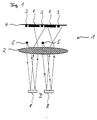
- the single figure shows a side view of a optoelectronic sensor system with integrated calibration device.
- the optoelectronic sensor system 1 comprises an input optic 2 and three CCD lines 3, which are arranged parallel to one another in a focal plane 4.
- the calibration device comprises two or more laser diodes 5, two or several CCD matrices 6 and a reference module 7, which is made up of composed of several sub-modules 8.
- the CCD matrices 6 of the calibration device are defined between the CCD lines 3 in the focal plane 4 arranged.
- the laser diodes 5 are between the focal plane 4 and the Input optics 2 arranged that this the field of view of the CCD lines 3rd do not bother.
- the entire calibration device with the exception of the Reference module 7 arranged on the floor in the optoelectronic sensor system 1 integrated.
- the beams of the laser diodes 5 are not through Lenses shown expanded, exit through the input optics 2 and meet the reference module 7, whose orientation parameters are highly precise are known.
- the beams are reflected by the reference module 7 and thrown onto the input optics 2, from where these onto the focal plane 4 and the CCD matrices 6 arranged there are imaged.
- All CCD matrices 6 can then determine the relative position and position of the focal plane 4 can be determined to the reference module 7. Based on the measured location and Position data can then be the offset for all six orientation parameters determine so that an absolute connection of the measured variables for the six Orientation parameters are given.
- the evaluation unit for the CCD lines 3 can be used, so that the hardware expenditure essentially on the CCD matrices 6 and Laser diodes 5 limited.
- the reference module 7 for example, concreted in a certain position at the airport are so that the reference module 7 defined in an unchangeable Position and location. This means that one can be carried out before each flight Calibrated the optoelectronic sensor system 1 again become.
Landscapes
- Engineering & Computer Science (AREA)
- Multimedia (AREA)
- Physics & Mathematics (AREA)
- General Physics & Mathematics (AREA)
- Radar, Positioning & Navigation (AREA)
- Remote Sensing (AREA)
- Length Measuring Devices By Optical Means (AREA)
- Navigation (AREA)
Abstract
Description
Claims (6)
- Kalibrationseinrichtung für die Orientierungsparameter von digitalen optoelektronischen Sensorsystemen (1) in Trägersystemen zur Fernerkundung, umfassend eine oder mehrere Lage- und Positionsbestimmungseinrichtungen im Trägersystem, mit denen die Orientierungsparameter im Flug bestimmbar sind, mindestens ein in Bezug auf das Trägersystem in definierter Richtung lichtemittierendes optoelektronisches Bauelement, mindestens einen flächenhaften optischen Detektor im Trägersystem und mindestens ein am Boden angeordnetes Referenzmodul (7), dessen Orientierungsparameter bekannt sind, wobei durch Auswertung der vom lichtemittierenden Bauelement emittierten, vom Referenzmodul (7) reflektierten und vom flächenhaften Detektor empfangenen Strahlung die Offsets der Orientierungsparameter des oder der Lage- und Positionsbestimmungseinrichtungen bestimmbar sind.
- Kalibrationsvorrichtung nach Anspruch 1, dadurch gekennzeichnet, daß die lichtemittierenden optoelektronischen Bauelemente als Laserdioden (5) ausgebildet sind.
- Kalibrationseinrichtung nach Anspruch 1 oder 2, dadurch gekennzeichnet, daß die flächenhaften optischen Detektoren als CCD-Matrizen (6) ausgebildet sind.
- Kalibrationsvorrichtung für einen CCD-Zeilenscanner nach einem der vorangegangenen Ansprüche, dadurch gekennzeichnet, daß zur Gewinnung von Fernerkundungsdaten CCD-Zeilen (3) auf der Fokalebene (4) einer Optik und die flächenhaften optischen Detektoren zwischen den CCD-Zeilen (3) in der gleichen Fokalebene (4) angeordnet sind.
- Kalibrationsvorrichtung nach Anspruch 4, dadurch gekennzeichnet, daß die lichtemittierenden optoelektronischen Bauelemente zwischen der Fokalebene (4) und der zugeordneten Optik (2) derart angeordnet sind, daß diese außerhalb des Strahlenganges der Nutzstrahlung der CCD-Zeilen (3) liegen.
- Kalibrationsvorrichtung nach einem der vorangegangenen Ansprüche, dadurch gekennzeichnet, daß das Referenzmodul (7) als einbetonierter Spiegel ausgebildet ist.
Applications Claiming Priority (2)
| Application Number | Priority Date | Filing Date | Title |
|---|---|---|---|
| DE19927012A DE19927012C1 (de) | 1999-06-07 | 1999-06-07 | Kalibrationseinrichtung für die Orientierungsparameter von digitalen optoelektronischen Sensorsystemen in Trägersystemen zur Fernerkundung |
| DE19927012 | 1999-06-07 |
Publications (2)
| Publication Number | Publication Date |
|---|---|
| EP1059507A1 true EP1059507A1 (de) | 2000-12-13 |
| EP1059507B1 EP1059507B1 (de) | 2003-11-05 |
Family
ID=7911135
Family Applications (1)
| Application Number | Title | Priority Date | Filing Date |
|---|---|---|---|
| EP00250155A Expired - Lifetime EP1059507B1 (de) | 1999-06-07 | 2000-05-19 | Kalibrationseinrichtung für optoelektronische Sensorsysteme |
Country Status (3)
| Country | Link |
|---|---|
| US (1) | US6864969B1 (de) |
| EP (1) | EP1059507B1 (de) |
| DE (2) | DE19927012C1 (de) |
Families Citing this family (4)
| Publication number | Priority date | Publication date | Assignee | Title |
|---|---|---|---|---|
| RU2432554C1 (ru) * | 2010-02-27 | 2011-10-27 | Государственное Научное Учреждение "Институт Физики Имени Б.И. Степанова Национальной Академии Наук Беларуси" | Способ радиационной калибровки спутникового сенсора высокого пространственного разрешения |
| RU2497075C1 (ru) * | 2012-06-04 | 2013-10-27 | Федеральное государственное бюджетное образовательное учреждение высшего профессионального образования "Московский государственный университет геодезии и картографии" (МИИГАиК) | Устройство тестирования и аттестации спутниковых gps-приемников (утасп) |
| US8878114B2 (en) * | 2012-08-16 | 2014-11-04 | Nanohmics, Inc. | Apparatus and methods for locating source of and analyzing electromagnetic radiation |
| CN105717498B (zh) * | 2016-02-04 | 2018-02-16 | 杭州南江机器人股份有限公司 | 激光测距仪俯仰角测量与校正系统及方法 |
Citations (3)
| Publication number | Priority date | Publication date | Assignee | Title |
|---|---|---|---|---|
| DE3802219A1 (de) * | 1988-01-26 | 1989-08-03 | Deutsche Forsch Luft Raumfahrt | Verfahren und einrichtung zur fernerkundung der erde |
| FR2713785A1 (fr) * | 1993-12-10 | 1995-06-16 | Centre Nat Etd Spatiales | Système de repérage d'orientation d'un instrument d'observation. |
| DE19746943A1 (de) * | 1997-10-23 | 1999-04-29 | Siemens Ag | Verfahren und Vorrichtung zur Ermittlung von Abweichungen für auf der Bearbeitung von Videosignalen basierenden Meßsystemen |
Family Cites Families (2)
| Publication number | Priority date | Publication date | Assignee | Title |
|---|---|---|---|---|
| CH599536A5 (de) * | 1975-09-02 | 1978-05-31 | Kern & Co Ag | |
| DE4314742C2 (de) * | 1993-05-04 | 1997-02-20 | Industrieanlagen Betriebsges | Verfahren und Anordnung zur hochgenauen Datengewinnung aus der Luft |
-
1999
- 1999-06-07 DE DE19927012A patent/DE19927012C1/de not_active Expired - Fee Related
-
2000
- 2000-05-19 EP EP00250155A patent/EP1059507B1/de not_active Expired - Lifetime
- 2000-05-19 DE DE50004297T patent/DE50004297D1/de not_active Expired - Lifetime
- 2000-06-07 US US09/588,894 patent/US6864969B1/en not_active Expired - Fee Related
Patent Citations (3)
| Publication number | Priority date | Publication date | Assignee | Title |
|---|---|---|---|---|
| DE3802219A1 (de) * | 1988-01-26 | 1989-08-03 | Deutsche Forsch Luft Raumfahrt | Verfahren und einrichtung zur fernerkundung der erde |
| FR2713785A1 (fr) * | 1993-12-10 | 1995-06-16 | Centre Nat Etd Spatiales | Système de repérage d'orientation d'un instrument d'observation. |
| DE19746943A1 (de) * | 1997-10-23 | 1999-04-29 | Siemens Ag | Verfahren und Vorrichtung zur Ermittlung von Abweichungen für auf der Bearbeitung von Videosignalen basierenden Meßsystemen |
Also Published As
| Publication number | Publication date |
|---|---|
| US6864969B1 (en) | 2005-03-08 |
| DE50004297D1 (de) | 2003-12-11 |
| EP1059507B1 (de) | 2003-11-05 |
| DE19927012C1 (de) | 2001-01-18 |
Similar Documents
| Publication | Publication Date | Title |
|---|---|---|
| DE19528465C2 (de) | Verfahren und Vorrichtung zur schnellen Erfassung der Lage einer Zielmarke | |
| DE3426505C2 (de) | ||
| EP2765388B1 (de) | Mobiler Feld-Controller zur Messung und Fernsteuerung | |
| DE3888732T2 (de) | Verfahren und Vorrichtung für laser-optische Navigation. | |
| DE112005001760B4 (de) | Positionsverfolgungs- und Steuersystem mit einem Kombinations-Laserdetektor- und Globalnavigationssatellitenempfänger-System | |
| DE3408437C2 (de) | Vorrichtung zur Positionsbestimmung eines vorgepreßten Hohlprofilstranges | |
| EP1659417A1 (de) | Verfahren zur Bestimmung der Ausrichtung eines Ausrichtungsindikators | |
| EP2806248B1 (de) | Verfahren zur Kalibrierung einer Erfassungseinrichtung und Erfassungseinrichtung | |
| EP1673589B1 (de) | Verfahren und vorrichtung zur bestimmung der aktualposition eines geodätischen instrumentes | |
| DE102011116303B3 (de) | Geodätisches Messsystem und Verfahren zum Betreiben eines geodätischen Messsystems | |
| EP1681533A1 (de) | Verfahren und geodätisches Gerät zur Vermessung wenigstens eines Zieles | |
| DE102016204140B3 (de) | Vorrichtung und Verfahren zur Kalibrierung einer Lichtlaufzeitkamera | |
| AT509103A1 (de) | Verfahren und vorrichtung zur stützung der messgenauigkeit von gps/imu-systemen | |
| EP3264034A1 (de) | Vermessungsgerät mit höhenmesssystem und verfahren zum messen einer höhe | |
| DE102013015892B4 (de) | Positionsbestimmung eines Fahrzeugs auf oder über einer Planetenoberfläche | |
| EP1703300A1 (de) | Verfahren und System zur Bestimmung von Position und Orientierung eines Objekts | |
| DE112012007096B4 (de) | Trackereinheit und Verfahren in einer Trackereinheit | |
| DE10155488A1 (de) | Verfahren zur Erfassung der Oberfläche einer Fahrbahn | |
| EP2511656A1 (de) | Vermessungssystem zur Bestimmung von 3D-Koordinaten einer Objektoberfläche | |
| EP2669707A1 (de) | Verfahren und handhaltbares Entfernungsmessgerät zur indirekten Entfernungsmessung mittels bildgestützter Winkelbestimmungsfunktion | |
| KR101394881B1 (ko) | 하나 이상의 타겟들의 지리적 위치측정 방법 | |
| DE102015117184B4 (de) | Vermessungsinstrument | |
| DE102012111345B4 (de) | Mobiles Handgerät zur Ausrichtung eines Sensors | |
| Mandlburger et al. | Evaluation of consumer-grade and survey-grade UAV-LIDAR | |
| DE19927012C1 (de) | Kalibrationseinrichtung für die Orientierungsparameter von digitalen optoelektronischen Sensorsystemen in Trägersystemen zur Fernerkundung |
Legal Events
| Date | Code | Title | Description |
|---|---|---|---|
| PUAI | Public reference made under article 153(3) epc to a published international application that has entered the european phase |
Free format text: ORIGINAL CODE: 0009012 |
|
| AK | Designated contracting states |
Kind code of ref document: A1 Designated state(s): CH DE FR IT LI |
|
| AX | Request for extension of the european patent |
Free format text: AL;LT;LV;MK;RO;SI |
|
| 17P | Request for examination filed |
Effective date: 20010612 |
|
| AKX | Designation fees paid |
Free format text: CH DE FR IT LI |
|
| GRAH | Despatch of communication of intention to grant a patent |
Free format text: ORIGINAL CODE: EPIDOS IGRA |
|
| GRAS | Grant fee paid |
Free format text: ORIGINAL CODE: EPIDOSNIGR3 |
|
| GRAA | (expected) grant |
Free format text: ORIGINAL CODE: 0009210 |
|
| AK | Designated contracting states |
Kind code of ref document: B1 Designated state(s): CH DE FR IT LI |
|
| REG | Reference to a national code |
Ref country code: CH Ref legal event code: EP |
|
| REF | Corresponds to: |
Ref document number: 50004297 Country of ref document: DE Date of ref document: 20031211 Kind code of ref document: P |
|
| REG | Reference to a national code |
Ref country code: CH Ref legal event code: NV Representative=s name: PATENTANWALTSBUERO JEAN HUNZIKER |
|
| ET | Fr: translation filed | ||
| PLBE | No opposition filed within time limit |
Free format text: ORIGINAL CODE: 0009261 |
|
| STAA | Information on the status of an ep patent application or granted ep patent |
Free format text: STATUS: NO OPPOSITION FILED WITHIN TIME LIMIT |
|
| 26N | No opposition filed |
Effective date: 20040806 |
|
| PGFP | Annual fee paid to national office [announced via postgrant information from national office to epo] |
Ref country code: FR Payment date: 20060519 Year of fee payment: 7 |
|
| PGFP | Annual fee paid to national office [announced via postgrant information from national office to epo] |
Ref country code: CH Payment date: 20060524 Year of fee payment: 7 |
|
| PGFP | Annual fee paid to national office [announced via postgrant information from national office to epo] |
Ref country code: IT Payment date: 20060531 Year of fee payment: 7 |
|
| REG | Reference to a national code |
Ref country code: CH Ref legal event code: PL |
|
| PG25 | Lapsed in a contracting state [announced via postgrant information from national office to epo] |
Ref country code: LI Free format text: LAPSE BECAUSE OF NON-PAYMENT OF DUE FEES Effective date: 20070531 Ref country code: CH Free format text: LAPSE BECAUSE OF NON-PAYMENT OF DUE FEES Effective date: 20070531 |
|
| REG | Reference to a national code |
Ref country code: FR Ref legal event code: ST Effective date: 20080131 |
|
| PG25 | Lapsed in a contracting state [announced via postgrant information from national office to epo] |
Ref country code: FR Free format text: LAPSE BECAUSE OF NON-PAYMENT OF DUE FEES Effective date: 20070531 |
|
| PG25 | Lapsed in a contracting state [announced via postgrant information from national office to epo] |
Ref country code: IT Free format text: LAPSE BECAUSE OF NON-PAYMENT OF DUE FEES Effective date: 20070519 |
|
| PGFP | Annual fee paid to national office [announced via postgrant information from national office to epo] |
Ref country code: DE Payment date: 20190412 Year of fee payment: 20 |