EP1059453A1 - Scroll compressor - Google Patents
Scroll compressor Download PDFInfo
- Publication number
- EP1059453A1 EP1059453A1 EP00111856A EP00111856A EP1059453A1 EP 1059453 A1 EP1059453 A1 EP 1059453A1 EP 00111856 A EP00111856 A EP 00111856A EP 00111856 A EP00111856 A EP 00111856A EP 1059453 A1 EP1059453 A1 EP 1059453A1
- Authority
- EP
- European Patent Office
- Prior art keywords
- scroll
- end plate
- fixed scroll
- face
- back pressure
- Prior art date
- Legal status (The legal status is an assumption and is not a legal conclusion. Google has not performed a legal analysis and makes no representation as to the accuracy of the status listed.)
- Granted
Links
- 238000007906 compression Methods 0.000 claims abstract description 17
- 230000006835 compression Effects 0.000 claims abstract description 12
- CURLTUGMZLYLDI-UHFFFAOYSA-N Carbon dioxide Chemical compound O=C=O CURLTUGMZLYLDI-UHFFFAOYSA-N 0.000 claims description 40
- 229910002092 carbon dioxide Inorganic materials 0.000 claims description 37
- 239000001569 carbon dioxide Substances 0.000 claims description 3
- 239000012071 phase Substances 0.000 description 7
- 239000003507 refrigerant Substances 0.000 description 4
- 238000001816 cooling Methods 0.000 description 3
- 230000003247 decreasing effect Effects 0.000 description 3
- 239000012530 fluid Substances 0.000 description 3
- 230000015556 catabolic process Effects 0.000 description 2
- 238000006731 degradation reaction Methods 0.000 description 2
- 239000007791 liquid phase Substances 0.000 description 2
- 239000006096 absorbing agent Substances 0.000 description 1
- 230000005540 biological transmission Effects 0.000 description 1
- 230000008878 coupling Effects 0.000 description 1
- 238000010168 coupling process Methods 0.000 description 1
- 238000005859 coupling reaction Methods 0.000 description 1
- 230000000593 degrading effect Effects 0.000 description 1
- 238000010586 diagram Methods 0.000 description 1
- 238000001704 evaporation Methods 0.000 description 1
- 230000008020 evaporation Effects 0.000 description 1
- 239000007788 liquid Substances 0.000 description 1
- 238000000034 method Methods 0.000 description 1
- 239000011555 saturated liquid Substances 0.000 description 1
- 238000007789 sealing Methods 0.000 description 1
Images


Classifications
-
- F—MECHANICAL ENGINEERING; LIGHTING; HEATING; WEAPONS; BLASTING
- F04—POSITIVE - DISPLACEMENT MACHINES FOR LIQUIDS; PUMPS FOR LIQUIDS OR ELASTIC FLUIDS
- F04C—ROTARY-PISTON, OR OSCILLATING-PISTON, POSITIVE-DISPLACEMENT MACHINES FOR LIQUIDS; ROTARY-PISTON, OR OSCILLATING-PISTON, POSITIVE-DISPLACEMENT PUMPS
- F04C18/00—Rotary-piston pumps specially adapted for elastic fluids
- F04C18/02—Rotary-piston pumps specially adapted for elastic fluids of arcuate-engagement type, i.e. with circular translatory movement of co-operating members, each member having the same number of teeth or tooth-equivalents
-
- F—MECHANICAL ENGINEERING; LIGHTING; HEATING; WEAPONS; BLASTING
- F04—POSITIVE - DISPLACEMENT MACHINES FOR LIQUIDS; PUMPS FOR LIQUIDS OR ELASTIC FLUIDS
- F04C—ROTARY-PISTON, OR OSCILLATING-PISTON, POSITIVE-DISPLACEMENT MACHINES FOR LIQUIDS; ROTARY-PISTON, OR OSCILLATING-PISTON, POSITIVE-DISPLACEMENT PUMPS
- F04C27/00—Sealing arrangements in rotary-piston pumps specially adapted for elastic fluids
- F04C27/005—Axial sealings for working fluid
-
- F—MECHANICAL ENGINEERING; LIGHTING; HEATING; WEAPONS; BLASTING
- F04—POSITIVE - DISPLACEMENT MACHINES FOR LIQUIDS; PUMPS FOR LIQUIDS OR ELASTIC FLUIDS
- F04C—ROTARY-PISTON, OR OSCILLATING-PISTON, POSITIVE-DISPLACEMENT MACHINES FOR LIQUIDS; ROTARY-PISTON, OR OSCILLATING-PISTON, POSITIVE-DISPLACEMENT PUMPS
- F04C2210/00—Fluid
- F04C2210/10—Fluid working
- F04C2210/1027—CO2
-
- F—MECHANICAL ENGINEERING; LIGHTING; HEATING; WEAPONS; BLASTING
- F04—POSITIVE - DISPLACEMENT MACHINES FOR LIQUIDS; PUMPS FOR LIQUIDS OR ELASTIC FLUIDS
- F04C—ROTARY-PISTON, OR OSCILLATING-PISTON, POSITIVE-DISPLACEMENT MACHINES FOR LIQUIDS; ROTARY-PISTON, OR OSCILLATING-PISTON, POSITIVE-DISPLACEMENT PUMPS
- F04C2210/00—Fluid
- F04C2210/10—Fluid working
- F04C2210/1072—Oxygen (O2)
Definitions
- the present invention relates to a scroll compressor, in particular, one suitable for operation in a vapour-compression refrigerating cycle which uses a refrigerant, such as CO 2 , in a supercritical area thereof.
- a refrigerant such as CO 2
- CO 2 in the gas phase is compressed using a compressor (A ⁇ B), and this hot and compressed CO 2 in the gas phase is cooled using a gas cooler (B ⁇ C).
- This cooled gas is further decompressed using a decompressor (C ⁇ D), and CO 2 in the gas-liquid phase is then vaporized (D ⁇ A), so that latent heat with respect to the evaporation is taken from an external fluid such as air, thereby cooling the external fluid.
- the critical temperature of CO 2 is approximately 31°C, that is, lower than that of Freon, the conventional refrigerant. Therefore, when the temperature of the outside air is high in the summer season or the like, the temperature of CO 2 at the gas cooler side is higher than the critical temperature of CO 2 . Therefore, in this case, CO 2 is not condensed at the outlet side of the gas cooler (that is, line segment B-C in Fig. 3 does not intersect with the saturated liquid curve SL).
- the condition at the outlet side of the gas cooler (corresponding to point C in Fig. 3) depends on the discharge pressure of the compressor and the CO 2 temperature at the outlet side of the gas cooler, and this CO 2 temperature at the outlet side depends on the discharge ability of the gas cooler and the outside temperature (which cannot be controlled).
- the condition at the outlet side of the gas cooler i.e., point C
- the discharge pressure of the compressor i.e., the pressure at the outlet side of the gas cooler. That is, in order to keep sufficient cooling ability (i.e., enthalpy difference) when the temperature of the outside air is high in the summer season or the like, higher pressure at the outlet side of the gas cooler is necessary as shown in the cycle E ⁇ F ⁇ G ⁇ H ⁇ E in Fig. 3. In order to satisfy this condition, the operating pressure of the compressor must be higher in comparison with the conventional refrigerating cycle using Freon.
- the operating pressure of the compressor is 3 kg/cm 2 in case of using R134 (i.e., conventional Freon), but 40 kg/cm 2 in case of CO 2 .
- the operation stopping pressure of the compressor of this example is 15 kg/cm 2 in case of using R134, but 100 kg/cm 2 in case of CO 2 .
- a general scroll compressor comprises a casing; a fixed scroll and a revolving scroll in the housing, each scroll comprising an end plate and a spiral protrusion built on an inner surface of the end plate, said inner surface facing the other end plate so as to engage the protrusions of each scroll and form a spiral compression chamber.
- the introduced working gas is compressed in the compression chamber and then discharged according to the revolving operation of the revolving scroll.
- the degradation of the operational ability of such a scroll compressor using CO 2 as the working gas and having high operating pressure
- due to the leakage of the working gas may cause a problem. Therefore, in order to prevent such degradation, a floating structure is adopted, in which the fixed scroll can move only in its axial direction, and the back face of this fixed scroll is supported using a back pressure block.
- top clearance a discharge port of the compressed gas in the end plate of the fixed scroll and the back pressure block, and to attach a discharge valve at the outside of the back pressure block. Therefore, the clearance volume of the top clearance is large, and thus large recompressive force is necessary, thereby degrading the operational ability of the compressor.
- an objective of the present invention is to provide a scroll compressor comprising a discharge port as small as possible, which requires less recompressive force and has improved operational ability.
- the present invention provides a scroll compressor comprising:
- the discharge port is formed only in the end plate of the fixed scroll, and the discharge valve for opening and closing the discharge port is directly attached to the end plate of the fixed scroll. Therefore, it is unnecessary to form a discharge port in the back pressure block and the length and volume of the discharge port can be decreased. As a result, lower recompressive force is necessary, thereby decreasing the necessary energy and improving the operational ability.
- the back pressure block and the fixed scroll have separate bodies, and the scroll compressor has fastening means for detachably attaching the back pressure block to the fixed scroll. Accordingly, the discharge valve can be fastened to the end plate of the fixed scroll before the back pressure block is attached to the fixed scroll. Therefore, the discharge valve can be easily attached and the place of the attachment is less limited.
- the working gas is carbon dioxide.
- the present invention can be effectively applied to a scroll compressor which uses a refrigerating cycle using CO 2 as the working gas, and which has a high operating pressure.
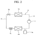
- the CO 2 cycle (structure) including the scroll compressor according to the present invention will be explained with reference to Fig. 2.
- the CO 2 cycle S in Fig. 2 is applied, for example, to the air conditioner of a vehicle.
- Reference numeral 1 indicates a scroll compressor for compressing CO 2 in the gas phase.
- This scroll compressor 1 receives driving force from a driving power supply (not shown) such as an engine.
- Reference numeral 1a indicates a gas cooler for heat-exchanging CO 2 compressed in the scroll compressor 1 and outside air (or the like), so as to cool CO 2 .
- Reference numeral 1b indicates a pressure control valve for controlling the pressure at the outlet side of the gas cooler 1a according to the CO 2 temperature at the outlet side of the gas cooler 1a.
- Reference numeral 1d indicates an evaporator (i.e., heat absorber) as an air cooling means in the cabin of the vehicle.
- CO 2 in the gas-liquid two-phase state is vaporized (or evaporated) in the evaporator 1d, CO 2 takes heat (corresponding to the latent heat of CO 2 ) from the air in the cabin so that the air in the cabin is cooled.
- Reference numeral 1e indicates an accumulator for temporarily storing CO 2 in the gas phase.
- the scroll compressor 1, gas cooler 1a, pressure control valve 1b, restrictor 1c, evaporator 1d, and accumulator 1e are connected via piping 1f so as to form a closed circuit.
- Housing (or casing) 1A of scroll compressor 1 includes cup-like main body 2, and front case (i.e., crank case) 4 fastened to the main body 2 via bolt 3.
- Reference numeral 5 indicates a crank shaft which pierces the front case 4 and is supported via main bearing 6 and sub bearing 7 by the front case 4 in a freely-rotatable form.
- the rotation of the engine (not shown) of the vehicle is transmitted via a known electromagnetic clutch 32 to the crank shaft 5.
- Reference numerals 32a and 32b respectively indicate the coil and pulley of the electromagnetic clutch 32.
- fixed scroll 8 and revolving scroll 9 are provided in the housing 1A.
- the fixed scroll 8 comprises end plate 10 and spiral protrusion (i.e., lap) 11 disposed on a surface of the plate 11, and the surface facing end plate 17 explained later.
- a ring-shaped back pressure block 13 is detachably attached to the back face of end plate 10 by using a plurality of bolts 12 as fastening means.
- O rings 14a and 14b are provided (or embedded) in the inner-peripheral and outer-peripheral faces of the back pressure block 13. These O rings 14a and 14b closely contact the inner-peripheral face of main body 2 of the casing, and high-pressure chamber (discharge chamber, explained later) 16 is separated from low-pressure chamber 15 (suction chamber) in the main body 2 of the casing.
- the high-pressure chamber 16 consists of a space surrounded by smaller-diameter face 13a of the back pressure block 13, a space surrounded by larger-diameter face 13b of the back pressure block 13, this space being formed continuously with the above space surrounded by face 13a, and a space surrounded by concave portion 10a formed in the back face of the end plate 10 of fixed scroll 8, this space being formed continuously with the above space surrounded by face 13b.
- discharge port 34 i.e., top clearance
- discharge valve 35 for opening/closing this discharge port 34 is provided in the concave portion 10a.
- the revolving scroll 9 comprises end plate 17 and spiral protrusion (i.e., lap) 18 which is disposed on a surface of the plate 17, the surface facing the end plate 10.
- the shape of the spiral protrusion 18 is substantially the same as that of the spiral protrusion 11 of the fixed scroll 8.
- a ring-shaped plate spring 20a is provided between the fixed scroll 8 and the main body 2 of the casing. A plurality of predetermined positions of the plate spring 20a are alternately fastened to the fixed scroll 8 and to the main body 2 via bolts 20b. According to this structure, the fixed scroll 8 can move only in its axial direction by the (amount of) maximum flexure of plate spring 20a in the axial direction (i.e., a floating structure).
- the above ring-shaped plate springs 20a and bolts 20a form fixed scroll supporting apparatus (or axial-direction compliance supporting apparatus) 20. Between the portion protruding from the back face of the back pressure block 13 and housing 1A, gap C is provided, so that the back pressure block 13 can move in the axial direction described above.
- the fixed scroll 8 and the revolving scroll 9 are engaged in a manner such that the axes of these scrolls are eccentrically separated from each other by the radius of revolution (that is, in an eccentric form), and the phases of these scrolls differ from each other by 180° (refer to Fig. 1).
- tip seals (not shown), provided and buried at the head surface of spiral protrusion 11, are in close contact with the inner surface (facing the end plate 10) of end plate 17, while tip seals (not shown), provided and buried at the head surface of spiral protrusion 18, are in close contact with the inner surface (facing the end plate 17) of end plate 10.
- a boss 22 is provided on (or projects from) a central area of the outer surface of the end plate 17.
- a freely-rotatable drive bush 23 is inserted in the boss 22 via revolving bearing (or drive bearing) 24 which also functions as a radial bearing.
- a freely-rotatable eccentric shaft 26, projecting from the inner-side end of the crank shaft 5, is inserted in through hole 25 provided in the drive bush 23.
- thrust ball bearing 19 for supporting the revolving scroll 9 is provided between the outer-circumferential edge of the outer surface of end plate 17 and the front case 4.
- a known mechanical seal (i.e., shaft seal) 28 used for sealing a shaft is provided around the crank shaft 5, and this mechanical seal 28 comprises seat ring 28a fixed to the front case 4, and slave ring 28b which rotates together with crank shaft 5.
- This slave ring 28b is forced by forcing member 28c towards seat ring 28a and closely contacts the seat ring 28a, so that the slave ring 28b rotationally slides on the seat ring 28a in accordance with the rotation of the crank shaft 5.
- the revolving scroll 9 When the rotation of the vehicle engine is transmitted to the crank shaft 5 by energizing the coil 32a of the electromagnetic clutch 32, the revolving scroll 9 is driven by the rotation of the crank shaft 5, transmitted via the revolution driving mechanism consisting of eccentric shaft 26, through hole 25, drive bush 23, revolving bearing 24, and boss 22.
- the revolving scroll 9 revolves along a circular orbit having a radius of revolution, while rotation of the scroll 9 is prohibited by the rotation-preventing ring 27.
- the working gas (refer to arrow A), which has flowed into suction chamber 15 through a suction inlet (not shown), enters enclosed space 21a from an opening at the ends of the spiral protrusions 11 and 18 and reaches center space 21c while the gas is compressed.
- the compressed gas then passes through discharge port 34 provided in the end plate 10 of the fixed scroll 8, and opens discharge valve 35, so that the gas is discharged into high-pressure chamber 16.
- the gas is further discharged outside via discharge outlet 38.
- the fluid introduced from the suction chamber 15 is compressed in the enclosed spaces 21a and 21b, and this compressed gas is discharged.
- discharge port (i.e., top clearance) 34 is formed only in the end plate 10 of fixed scroll 8, and discharge valve 35 for opening/closing the discharge port 34 is directly attached to the end plate 10 of fixed scroll 8. Therefore, it is unnecessary to form discharge port 34 in the back pressure block 13, thereby decreasing the length and volume of the discharge port 34. Accordingly, lower recompressive force of the compressor is necessary, thereby improving the operational ability.
- back pressure block 13 and fixed scroll 8 have separate bodies, and the back pressure block 13 is detachably attached to the fixed scroll 8 using bolts 12 (i.e., fastening means).
- bolts 12 i.e., fastening means
- the open-type compressor is applied to the CO 2 cycle using CO 2 as the working gas; however, the application is not limited to this type, and the compressor according to the present invention can be applied to the vapour-compression refrigerating cycle using a conventional working gas such as Freon.
Landscapes
- Engineering & Computer Science (AREA)
- Mechanical Engineering (AREA)
- General Engineering & Computer Science (AREA)
- Rotary Pumps (AREA)
- Applications Or Details Of Rotary Compressors (AREA)
- Compressor (AREA)
- Check Valves (AREA)
Abstract
Description
- The present invention relates to a scroll compressor, in particular, one suitable for operation in a vapour-compression refrigerating cycle which uses a refrigerant, such as CO2, in a supercritical area thereof.
- As for the vapour-compression refrigerating cycle, one of the recently proposed measures to avoid the use of Freon (fron, a refrigerant) in order to protect the environment is the use of a refrigerating cycle using CO2 as the working gas (i.e., the refrigerant gas). This cycle is called "CO2 cycle" below. An example thereof is disclosed in Japanese Examined Patent Application, Second Publication, No. Hei 7-18602. The operation of this CO2 cycle is similar to the operation of a conventional vapour-compression refrigerating cycle using Freon. That is, as shown by the cycle A → B → C → D → A in Fig. 3 (which shows a CO2 Mollier chart), CO2 in the gas phase is compressed using a compressor (A → B), and this hot and compressed CO2 in the gas phase is cooled using a gas cooler (B → C). This cooled gas is further decompressed using a decompressor (C → D), and CO2 in the gas-liquid phase is then vaporized (D → A), so that latent heat with respect to the evaporation is taken from an external fluid such as air, thereby cooling the external fluid.
- The critical temperature of CO2 is approximately 31°C, that is, lower than that of Freon, the conventional refrigerant. Therefore, when the temperature of the outside air is high in the summer season or the like, the temperature of CO2 at the gas cooler side is higher than the critical temperature of CO2. Therefore, in this case, CO2 is not condensed at the outlet side of the gas cooler (that is, line segment B-C in Fig. 3 does not intersect with the saturated liquid curve SL). In addition, the condition at the outlet side of the gas cooler (corresponding to point C in Fig. 3) depends on the discharge pressure of the compressor and the CO2 temperature at the outlet side of the gas cooler, and this CO2 temperature at the outlet side depends on the discharge ability of the gas cooler and the outside temperature (which cannot be controlled). Therefore, substantially, the CO2 temperature at the outlet side of the gas cooler cannot be controlled. Accordingly, the condition at the outlet side of the gas cooler (i.e., point C) can be controlled by controlling the discharge pressure of the compressor (i.e., the pressure at the outlet side of the gas cooler). That is, in order to keep sufficient cooling ability (i.e., enthalpy difference) when the temperature of the outside air is high in the summer season or the like, higher pressure at the outlet side of the gas cooler is necessary as shown in the cycle E → F → G → H → E in Fig. 3. In order to satisfy this condition, the operating pressure of the compressor must be higher in comparison with the conventional refrigerating cycle using Freon. In an example of an air conditioner used in a vehicle, the operating pressure of the compressor is 3 kg/cm2 in case of using R134 (i.e., conventional Freon), but 40 kg/cm2 in case of CO2. In addition, the operation stopping pressure of the compressor of this example is 15 kg/cm2 in case of using R134, but 100 kg/cm2 in case of CO2.
- Here, a general scroll compressor comprises a casing; a fixed scroll and a revolving scroll in the housing, each scroll comprising an end plate and a spiral protrusion built on an inner surface of the end plate, said inner surface facing the other end plate so as to engage the protrusions of each scroll and form a spiral compression chamber. In this structure, the introduced working gas is compressed in the compression chamber and then discharged according to the revolving operation of the revolving scroll. The degradation of the operational ability of such a scroll compressor (using CO2 as the working gas and having high operating pressure) due to the leakage of the working gas may cause a problem. Therefore, in order to prevent such degradation, a floating structure is adopted, in which the fixed scroll can move only in its axial direction, and the back face of this fixed scroll is supported using a back pressure block.
- In the above scroll compressor having the floating structure, it is necessary to form a discharge port (called "top clearance") of the compressed gas in the end plate of the fixed scroll and the back pressure block, and to attach a discharge valve at the outside of the back pressure block. Therefore, the clearance volume of the top clearance is large, and thus large recompressive force is necessary, thereby degrading the operational ability of the compressor.
- In consideration of the above circumstances, an objective of the present invention is to provide a scroll compressor comprising a discharge port as small as possible, which requires less recompressive force and has improved operational ability.
- Therefore, the present invention provides a scroll compressor comprising:
- a casing;
- a fixed scroll, movable in its axial direction, provided in the housing and comprising an end plate and a spiral protrusion built on one face of the end plate;
- a revolving scroll provided in the casing and comprising an end plate and a spiral protrusion built on one face of the end plate, wherein the spiral protrusions of each scroll are engaged with each other so as to form a spiral compression chamber; and
- a back pressure block for supporting the back face of the fixed scroll, wherein:
- an introduced working gas is compressed in the compression chamber and then discharged according to the revolving operation of the revolving scroll;
- a discharge port joining the compression chamber is formed in the end plate of the fixed scroll;
- the back pressure block has a ring shape, and the inner-peripheral face of the back pressure block and the back face of the fixed scroll form a high-pressure chamber; and
- a discharge valve for opening and closing the discharge port is attached to the end plate of the fixed scroll and is provided in the high-pressure chamber.
-
- In this structure, the discharge port is formed only in the end plate of the fixed scroll, and the discharge valve for opening and closing the discharge port is directly attached to the end plate of the fixed scroll. Therefore, it is unnecessary to form a discharge port in the back pressure block and the length and volume of the discharge port can be decreased. As a result, lower recompressive force is necessary, thereby decreasing the necessary energy and improving the operational ability.
- Typically, the back pressure block and the fixed scroll have separate bodies, and the scroll compressor has fastening means for detachably attaching the back pressure block to the fixed scroll. Accordingly, the discharge valve can be fastened to the end plate of the fixed scroll before the back pressure block is attached to the fixed scroll. Therefore, the discharge valve can be easily attached and the place of the attachment is less limited.
- Preferably, the working gas is carbon dioxide. In this case, the present invention can be effectively applied to a scroll compressor which uses a refrigerating cycle using CO2 as the working gas, and which has a high operating pressure.
-
- Fig. 1 is a cross-sectional view in the longitudinal direction of an embodiment of the scroll compressor according to the present invention.
- Fig. 2 is a diagram showing a vapour-compression refrigerating cycle.
- Fig. 3 is a Mollier chart for CO2.
-
- Hereinafter, an embodiment of the scroll compressor according to the present invention will be explained with reference to the drawings.
- First, the CO2 cycle (structure) including the scroll compressor according to the present invention will be explained with reference to Fig. 2. The CO2 cycle S in Fig. 2 is applied, for example, to the air conditioner of a vehicle.
Reference numeral 1 indicates a scroll compressor for compressing CO2 in the gas phase. Thisscroll compressor 1 receives driving force from a driving power supply (not shown) such as an engine.Reference numeral 1a indicates a gas cooler for heat-exchanging CO2 compressed in thescroll compressor 1 and outside air (or the like), so as to cool CO2.Reference numeral 1b indicates a pressure control valve for controlling the pressure at the outlet side of thegas cooler 1a according to the CO2 temperature at the outlet side of thegas cooler 1a. CO2 is decompressed by thepressure control valve 1b andrestrictor 1c, and CO2 enters into the gas-liquid phase (i.e., in the two-phase state).Reference numeral 1d indicates an evaporator (i.e., heat absorber) as an air cooling means in the cabin of the vehicle. When CO2 in the gas-liquid two-phase state is vaporized (or evaporated) in theevaporator 1d, CO2 takes heat (corresponding to the latent heat of CO2) from the air in the cabin so that the air in the cabin is cooled.Reference numeral 1e indicates an accumulator for temporarily storing CO2 in the gas phase. Thescroll compressor 1,gas cooler 1a,pressure control valve 1b,restrictor 1c,evaporator 1d, andaccumulator 1e are connected viapiping 1f so as to form a closed circuit. - An embodiment of the
scroll compressor 1 will be explained with reference to Fig. 1. - Housing (or casing) 1A of
scroll compressor 1 includes cup-likemain body 2, and front case (i.e., crank case) 4 fastened to themain body 2 viabolt 3.Reference numeral 5 indicates a crank shaft which pierces thefront case 4 and is supported via main bearing 6 and sub bearing 7 by thefront case 4 in a freely-rotatable form. The rotation of the engine (not shown) of the vehicle is transmitted via a known electromagnetic clutch 32 to the crankshaft 5.Reference numerals electromagnetic clutch 32. - In the
housing 1A, fixedscroll 8 and revolvingscroll 9 are provided. - The fixed
scroll 8 comprisesend plate 10 and spiral protrusion (i.e., lap) 11 disposed on a surface of theplate 11, and the surface facingend plate 17 explained later. A ring-shaped backpressure block 13 is detachably attached to the back face ofend plate 10 by using a plurality ofbolts 12 as fastening means. O rings 14a and 14b are provided (or embedded) in the inner-peripheral and outer-peripheral faces of theback pressure block 13. These O rings 14a and 14b closely contact the inner-peripheral face ofmain body 2 of the casing, and high-pressure chamber (discharge chamber, explained later) 16 is separated from low-pressure chamber 15 (suction chamber) in themain body 2 of the casing. The high-pressure chamber 16 consists of a space surrounded by smaller-diameter face 13a of theback pressure block 13, a space surrounded by larger-diameter face 13b of theback pressure block 13, this space being formed continuously with the above space surrounded byface 13a, and a space surrounded byconcave portion 10a formed in the back face of theend plate 10 of fixedscroll 8, this space being formed continuously with the above space surrounded byface 13b. In theend plate 10 of fixedscroll 8, discharge port 34 (i.e., top clearance) is opened, and dischargevalve 35 for opening/closing thisdischarge port 34 is provided in theconcave portion 10a. - The revolving
scroll 9 comprisesend plate 17 and spiral protrusion (i.e., lap) 18 which is disposed on a surface of theplate 17, the surface facing theend plate 10. The shape of thespiral protrusion 18 is substantially the same as that of thespiral protrusion 11 of the fixedscroll 8. - A ring-shaped
plate spring 20a is provided between thefixed scroll 8 and themain body 2 of the casing. A plurality of predetermined positions of theplate spring 20a are alternately fastened to the fixedscroll 8 and to themain body 2 viabolts 20b. According to this structure, the fixedscroll 8 can move only in its axial direction by the (amount of) maximum flexure ofplate spring 20a in the axial direction (i.e., a floating structure). The above ring-shaped plate springs 20a andbolts 20a form fixed scroll supporting apparatus (or axial-direction compliance supporting apparatus) 20. Between the portion protruding from the back face of theback pressure block 13 andhousing 1A, gap C is provided, so that theback pressure block 13 can move in the axial direction described above. The fixedscroll 8 and the revolvingscroll 9 are engaged in a manner such that the axes of these scrolls are eccentrically separated from each other by the radius of revolution (that is, in an eccentric form), and the phases of these scrolls differ from each other by 180° (refer to Fig. 1). In addition, tip seals (not shown), provided and buried at the head surface ofspiral protrusion 11, are in close contact with the inner surface (facing the end plate 10) ofend plate 17, while tip seals (not shown), provided and buried at the head surface ofspiral protrusion 18, are in close contact with the inner surface (facing the end plate 17) ofend plate 10. Furthermore, the side faces of thespiral protrusions enclosed spaces scroll 9 to revolve, but prohibiting the rotation of thescroll 9 is provided between thefixed scroll 8 and revolvingscroll 9. - A
boss 22 is provided on (or projects from) a central area of the outer surface of theend plate 17. A freely-rotatable drive bush 23 is inserted in theboss 22 via revolving bearing (or drive bearing) 24 which also functions as a radial bearing. In addition, a freely-rotatableeccentric shaft 26, projecting from the inner-side end of thecrank shaft 5, is inserted in throughhole 25 provided in thedrive bush 23. Furthermore, thrustball bearing 19 for supporting the revolvingscroll 9 is provided between the outer-circumferential edge of the outer surface ofend plate 17 and thefront case 4. - A known mechanical seal (i.e., shaft seal) 28 used for sealing a shaft is provided around the
crank shaft 5, and this mechanical seal 28 comprisesseat ring 28a fixed to thefront case 4, and slave ring 28b which rotates together withcrank shaft 5. This slave ring 28b is forced by forcingmember 28c towardsseat ring 28a and closely contacts theseat ring 28a, so that the slave ring 28b rotationally slides on theseat ring 28a in accordance with the rotation of thecrank shaft 5. - The operation of the
scroll compressor 1 will be explained below. - When the rotation of the vehicle engine is transmitted to the crank
shaft 5 by energizing thecoil 32a of the electromagnetic clutch 32, the revolvingscroll 9 is driven by the rotation of thecrank shaft 5, transmitted via the revolution driving mechanism consisting ofeccentric shaft 26, throughhole 25,drive bush 23, revolvingbearing 24, andboss 22. The revolvingscroll 9 revolves along a circular orbit having a radius of revolution, while rotation of thescroll 9 is prohibited by the rotation-preventingring 27. - In this way, line-contact portions in the side faces of
spiral protrusions - Accordingly, the working gas (refer to arrow A), which has flowed into
suction chamber 15 through a suction inlet (not shown), entersenclosed space 21a from an opening at the ends of thespiral protrusions center space 21c while the gas is compressed. The compressed gas then passes throughdischarge port 34 provided in theend plate 10 of the fixedscroll 8, and opensdischarge valve 35, so that the gas is discharged into high-pressure chamber 16. The gas is further discharged outside viadischarge outlet 38. In this way, according to the revolution of the revolvingscroll 9, the fluid introduced from thesuction chamber 15 is compressed in theenclosed spaces - When the energizing process for
coil 32a of electromagnetic clutch 32 is released so as to stop transmission of the rotating force to crankshaft 5, the operation of thescroll compressor 1 is stopped. When thecoil 32a of electromagnetic clutch 32 is energized again, thescroll compressor 1 is activated again. - In the above-explained structure of the
scroll compressor 1, discharge port (i.e., top clearance) 34 is formed only in theend plate 10 of fixedscroll 8, and dischargevalve 35 for opening/closing thedischarge port 34 is directly attached to theend plate 10 of fixedscroll 8. Therefore, it is unnecessary to formdischarge port 34 in theback pressure block 13, thereby decreasing the length and volume of thedischarge port 34. Accordingly, lower recompressive force of the compressor is necessary, thereby improving the operational ability. - In addition, back
pressure block 13 and fixedscroll 8 have separate bodies, and theback pressure block 13 is detachably attached to the fixedscroll 8 using bolts 12 (i.e., fastening means). In this structure, it is possible to easily attachdischarge valve 35 to theend plate 10 of fixedscroll 8 before theback pressure block 13 is attached to the fixedscroll 8, and the place of attachment is less limited. - In the above explained embodiment, the open-type compressor is applied to the CO2 cycle using CO2 as the working gas; however, the application is not limited to this type, and the compressor according to the present invention can be applied to the vapour-compression refrigerating cycle using a conventional working gas such as Freon.
Claims (4)
- A scroll compressor comprising:a casing (1A);a fixed scroll (8), movable in its axial direction, provided in the housing and comprising an end plate (10) and a spiral protrusion built on one face of the end plate;a revolving scroll (9) provided in the casing and comprising an end plate (17) and a spiral protrusion built on one face of the end plate, wherein the spiral protrusions of each scroll are engaged with each other so as to form a spiral compression chamber; anda back pressure block (13) for supporting the back face of the fixed scroll, wherein:an introduced working gas is compressed in the compression chamber and then discharged according to the revolving operation of the revolving scroll;a discharge port (34) joining the compression chamber is formed in the end plate of the fixed scroll;the back pressure block has a ring shape, and the inner-peripheral face of the back pressure block and the back face of the fixed scroll form a high-pressure chamber; anda discharge valve (35) for opening and closing the discharge port is attached to the end plate of the fixed scroll and is provided in the high-pressure chamber.
- A scroll compressor as claimed in claim 1, wherein the back pressure block and the fixed scroll have separate bodies, and the scroll compressor has fastening means (12) for detachably attaching the back pressure block to the fixed scroll.
- A scroll compressor as claimed in claim 1, wherein the working gas is carbon dioxide.
- A scroll compressor as claimed in claim 2, wherein the working gas is carbon dioxide.
Applications Claiming Priority (2)
| Application Number | Priority Date | Filing Date | Title |
|---|---|---|---|
| JP11161692A JP2000352389A (en) | 1999-06-08 | 1999-06-08 | Scroll compressor |
| JP16169299 | 1999-06-08 |
Publications (2)
| Publication Number | Publication Date |
|---|---|
| EP1059453A1 true EP1059453A1 (en) | 2000-12-13 |
| EP1059453B1 EP1059453B1 (en) | 2006-08-16 |
Family
ID=15740058
Family Applications (1)
| Application Number | Title | Priority Date | Filing Date |
|---|---|---|---|
| EP00111856A Expired - Lifetime EP1059453B1 (en) | 1999-06-08 | 2000-06-08 | Scroll compressor |
Country Status (8)
| Country | Link |
|---|---|
| US (1) | US6287097B1 (en) |
| EP (1) | EP1059453B1 (en) |
| JP (1) | JP2000352389A (en) |
| KR (1) | KR100349479B1 (en) |
| CN (1) | CN1179130C (en) |
| AT (1) | ATE336660T1 (en) |
| DE (1) | DE60030037T2 (en) |
| NO (1) | NO20002911L (en) |
Families Citing this family (8)
| Publication number | Priority date | Publication date | Assignee | Title |
|---|---|---|---|---|
| JP2001055988A (en) | 1999-06-08 | 2001-02-27 | Mitsubishi Heavy Ind Ltd | Scroll compressor |
| KR100439651B1 (en) | 2000-11-06 | 2004-07-12 | 미츠비시 쥬고교 가부시키가이샤 | Scroll compressor |
| US7140851B2 (en) * | 2004-09-07 | 2006-11-28 | Chyn Tec. International Co., Ltd. | Axial compliance mechanism of scroll compressor |
| CN1782420B (en) * | 2004-11-30 | 2010-05-05 | 乐金电子(天津)电器有限公司 | Check valve device of scroll compressor |
| KR20090100689A (en) * | 2008-03-20 | 2009-09-24 | 엘지전자 주식회사 | Scroll compressor |
| CN102510951A (en) * | 2010-08-23 | 2012-06-20 | 松下电器产业株式会社 | Hermetically sealed compressor |
| JP6007737B2 (en) * | 2012-11-13 | 2016-10-12 | 株式会社豊田自動織機 | Scroll compressor |
| JP6578504B2 (en) * | 2013-04-30 | 2019-09-25 | パナソニックIpマネジメント株式会社 | Scroll compressor |
Citations (4)
| Publication number | Priority date | Publication date | Assignee | Title |
|---|---|---|---|---|
| GB2194291A (en) * | 1986-08-22 | 1988-03-02 | Copeland Corp | Scroll-type machine |
| US5346376A (en) * | 1993-08-20 | 1994-09-13 | General Motors Corporation | Axial thrust applying structure for the scrolls of a scroll type compressor |
| JPH0718602A (en) | 1993-06-29 | 1995-01-20 | Sekisui Chem Co Ltd | Embedded plug |
| US5435707A (en) * | 1993-06-14 | 1995-07-25 | Mitsubishi Jukogyo Kabushiki Kaisha | Scroll-type compressor with an elastically deformable top plate or end plate |
Family Cites Families (19)
| Publication number | Priority date | Publication date | Assignee | Title |
|---|---|---|---|---|
| US4892469A (en) * | 1981-04-03 | 1990-01-09 | Arthur D. Little, Inc. | Compact scroll-type fluid compressor with swing-link driving means |
| JPS6023284A (en) | 1983-07-15 | 1985-02-05 | 三菱電機株式会社 | Escalator for physically handicapped person |
| JPH0671791B2 (en) | 1983-07-20 | 1994-09-14 | キヤノン株式会社 | How to detect the amount of ink remaining in an ink jet printer |
| JPS61215481A (en) * | 1985-03-22 | 1986-09-25 | Toyoda Autom Loom Works Ltd | Scroll revolving radius varying mechanism of moving scroll in scroll type compressor |
| NO890076D0 (en) | 1989-01-09 | 1989-01-09 | Sinvent As | AIR CONDITIONING. |
| JPH04101001A (en) * | 1990-08-16 | 1992-04-02 | Mitsubishi Heavy Ind Ltd | Scroll type fluid machine |
| JPH05149269A (en) * | 1991-11-27 | 1993-06-15 | Mitsubishi Heavy Ind Ltd | Scroll type fluid machine |
| JPH0681781A (en) * | 1992-09-04 | 1994-03-22 | Nippondenso Co Ltd | Scroll compressor |
| JPH06173864A (en) * | 1992-12-10 | 1994-06-21 | Toshiba Corp | Scroll type compressor |
| JP3183752B2 (en) * | 1993-06-24 | 2001-07-09 | サンデン株式会社 | Scroll compressor |
| JP3129365B2 (en) * | 1993-08-30 | 2001-01-29 | 三菱重工業株式会社 | Scroll type fluid machine |
| JP3170109B2 (en) * | 1993-09-03 | 2001-05-28 | 三菱重工業株式会社 | Scroll type compressor |
| JP3236144B2 (en) * | 1993-09-14 | 2001-12-10 | 株式会社デンソー | Compressor |
| US5591018A (en) * | 1993-12-28 | 1997-01-07 | Matsushita Electric Industrial Co., Ltd. | Hermetic scroll compressor having a pumped fluid motor cooling means and an oil collection pan |
| JPH08319963A (en) * | 1995-03-22 | 1996-12-03 | Mitsubishi Electric Corp | Scroll compressor |
| JP3046523B2 (en) * | 1995-05-23 | 2000-05-29 | 株式会社豊田自動織機製作所 | Scroll compressor |
| JP3658831B2 (en) * | 1996-02-09 | 2005-06-08 | 松下電器産業株式会社 | Scroll compressor |
| JPH11241691A (en) * | 1998-02-25 | 1999-09-07 | Denso Corp | Scroll type electric compressor for CO2 |
| US6073454A (en) * | 1998-07-10 | 2000-06-13 | Spauschus Associates, Inc. | Reduced pressure carbon dioxide-based refrigeration system |
-
1999
- 1999-06-08 JP JP11161692A patent/JP2000352389A/en active Pending
-
2000
- 2000-04-28 KR KR1020000022838A patent/KR100349479B1/en not_active Expired - Fee Related
- 2000-06-06 CN CNB001180037A patent/CN1179130C/en not_active Expired - Lifetime
- 2000-06-07 NO NO20002911A patent/NO20002911L/en not_active Application Discontinuation
- 2000-06-07 US US09/588,707 patent/US6287097B1/en not_active Expired - Lifetime
- 2000-06-08 EP EP00111856A patent/EP1059453B1/en not_active Expired - Lifetime
- 2000-06-08 AT AT00111856T patent/ATE336660T1/en not_active IP Right Cessation
- 2000-06-08 DE DE60030037T patent/DE60030037T2/en not_active Expired - Lifetime
Patent Citations (4)
| Publication number | Priority date | Publication date | Assignee | Title |
|---|---|---|---|---|
| GB2194291A (en) * | 1986-08-22 | 1988-03-02 | Copeland Corp | Scroll-type machine |
| US5435707A (en) * | 1993-06-14 | 1995-07-25 | Mitsubishi Jukogyo Kabushiki Kaisha | Scroll-type compressor with an elastically deformable top plate or end plate |
| JPH0718602A (en) | 1993-06-29 | 1995-01-20 | Sekisui Chem Co Ltd | Embedded plug |
| US5346376A (en) * | 1993-08-20 | 1994-09-13 | General Motors Corporation | Axial thrust applying structure for the scrolls of a scroll type compressor |
Also Published As
| Publication number | Publication date |
|---|---|
| ATE336660T1 (en) | 2006-09-15 |
| CN1276480A (en) | 2000-12-13 |
| US6287097B1 (en) | 2001-09-11 |
| JP2000352389A (en) | 2000-12-19 |
| KR20010007032A (en) | 2001-01-26 |
| CN1179130C (en) | 2004-12-08 |
| DE60030037T2 (en) | 2007-02-22 |
| EP1059453B1 (en) | 2006-08-16 |
| NO20002911D0 (en) | 2000-06-07 |
| DE60030037D1 (en) | 2006-09-28 |
| NO20002911L (en) | 2000-12-11 |
| KR100349479B1 (en) | 2002-08-21 |
Similar Documents
| Publication | Publication Date | Title |
|---|---|---|
| KR100350750B1 (en) | Scroll compressor | |
| EP0043701B1 (en) | Capacity control for a scroll-type fluid displacement apparatus | |
| US11015598B2 (en) | Compressor having bushing | |
| EP1253323A2 (en) | Hermetic compressors | |
| US6428295B1 (en) | Scroll compressor for introducing high-pressure fluid to thrust-face side so as to decrease thrust load imposed on revolving scroll | |
| US20190345939A1 (en) | Compressor Having Bushing | |
| EP1059453B1 (en) | Scroll compressor | |
| EP1059450B1 (en) | Scroll compressor | |
| US6514059B1 (en) | Scroll compressor | |
| US6244840B1 (en) | Scroll compressor having end plates of fixed and revolving scrolls thicker than heights of spiral protrusions of the scrolls | |
| JP4664490B2 (en) | Scroll compressor | |
| JP2000346062A (en) | Thrust ball bearing and open type scroll compressor | |
| JP2002235683A (en) | Scroll compressor | |
| JP4995290B2 (en) | Design method of scroll compressor | |
| JP2002242859A (en) | Scroll compressor | |
| AU2003252946B2 (en) | Compressor pulse width modulation | |
| JP2007146860A (en) | Scroll compressor, vapor compression type refrigerating cycle, and air conditioner for vehicle |
Legal Events
| Date | Code | Title | Description |
|---|---|---|---|
| PUAI | Public reference made under article 153(3) epc to a published international application that has entered the european phase |
Free format text: ORIGINAL CODE: 0009012 |
|
| 17P | Request for examination filed |
Effective date: 20000608 |
|
| AK | Designated contracting states |
Kind code of ref document: A1 Designated state(s): AT BE CH CY DE DK ES FI FR GB GR IE IT LI LU MC NL PT SE |
|
| AX | Request for extension of the european patent |
Free format text: AL;LT;LV;MK;RO;SI |
|
| AKX | Designation fees paid |
Free format text: AT BE CH CY DE DK ES FI FR GB GR IE IT LI LU MC NL PT SE |
|
| 17Q | First examination report despatched |
Effective date: 20040903 |
|
| GRAP | Despatch of communication of intention to grant a patent |
Free format text: ORIGINAL CODE: EPIDOSNIGR1 |
|
| GRAS | Grant fee paid |
Free format text: ORIGINAL CODE: EPIDOSNIGR3 |
|
| GRAA | (expected) grant |
Free format text: ORIGINAL CODE: 0009210 |
|
| AK | Designated contracting states |
Kind code of ref document: B1 Designated state(s): AT BE CH CY DE DK ES FI FR GB GR IE IT LI LU MC NL PT SE |
|
| PG25 | Lapsed in a contracting state [announced via postgrant information from national office to epo] |
Ref country code: NL Free format text: LAPSE BECAUSE OF FAILURE TO SUBMIT A TRANSLATION OF THE DESCRIPTION OR TO PAY THE FEE WITHIN THE PRESCRIBED TIME-LIMIT Effective date: 20060816 Ref country code: LI Free format text: LAPSE BECAUSE OF FAILURE TO SUBMIT A TRANSLATION OF THE DESCRIPTION OR TO PAY THE FEE WITHIN THE PRESCRIBED TIME-LIMIT Effective date: 20060816 Ref country code: FI Free format text: LAPSE BECAUSE OF FAILURE TO SUBMIT A TRANSLATION OF THE DESCRIPTION OR TO PAY THE FEE WITHIN THE PRESCRIBED TIME-LIMIT Effective date: 20060816 Ref country code: CH Free format text: LAPSE BECAUSE OF FAILURE TO SUBMIT A TRANSLATION OF THE DESCRIPTION OR TO PAY THE FEE WITHIN THE PRESCRIBED TIME-LIMIT Effective date: 20060816 Ref country code: BE Free format text: LAPSE BECAUSE OF FAILURE TO SUBMIT A TRANSLATION OF THE DESCRIPTION OR TO PAY THE FEE WITHIN THE PRESCRIBED TIME-LIMIT Effective date: 20060816 Ref country code: IT Free format text: LAPSE BECAUSE OF FAILURE TO SUBMIT A TRANSLATION OF THE DESCRIPTION OR TO PAY THE FEE WITHIN THE PRESCRIBED TIME-LIMIT;WARNING: LAPSES OF ITALIAN PATENTS WITH EFFECTIVE DATE BEFORE 2007 MAY HAVE OCCURRED AT ANY TIME BEFORE 2007. THE CORRECT EFFECTIVE DATE MAY BE DIFFERENT FROM THE ONE RECORDED. Effective date: 20060816 Ref country code: AT Free format text: LAPSE BECAUSE OF FAILURE TO SUBMIT A TRANSLATION OF THE DESCRIPTION OR TO PAY THE FEE WITHIN THE PRESCRIBED TIME-LIMIT Effective date: 20060816 |
|
| REG | Reference to a national code |
Ref country code: GB Ref legal event code: FG4D |
|
| REG | Reference to a national code |
Ref country code: CH Ref legal event code: EP |
|
| REG | Reference to a national code |
Ref country code: IE Ref legal event code: FG4D |
|
| REF | Corresponds to: |
Ref document number: 60030037 Country of ref document: DE Date of ref document: 20060928 Kind code of ref document: P |
|
| PG25 | Lapsed in a contracting state [announced via postgrant information from national office to epo] |
Ref country code: SE Free format text: LAPSE BECAUSE OF FAILURE TO SUBMIT A TRANSLATION OF THE DESCRIPTION OR TO PAY THE FEE WITHIN THE PRESCRIBED TIME-LIMIT Effective date: 20061116 Ref country code: DK Free format text: LAPSE BECAUSE OF FAILURE TO SUBMIT A TRANSLATION OF THE DESCRIPTION OR TO PAY THE FEE WITHIN THE PRESCRIBED TIME-LIMIT Effective date: 20061116 |
|
| PG25 | Lapsed in a contracting state [announced via postgrant information from national office to epo] |
Ref country code: ES Free format text: LAPSE BECAUSE OF FAILURE TO SUBMIT A TRANSLATION OF THE DESCRIPTION OR TO PAY THE FEE WITHIN THE PRESCRIBED TIME-LIMIT Effective date: 20061127 |
|
| PG25 | Lapsed in a contracting state [announced via postgrant information from national office to epo] |
Ref country code: PT Free format text: LAPSE BECAUSE OF FAILURE TO SUBMIT A TRANSLATION OF THE DESCRIPTION OR TO PAY THE FEE WITHIN THE PRESCRIBED TIME-LIMIT Effective date: 20070116 |
|
| NLV1 | Nl: lapsed or annulled due to failure to fulfill the requirements of art. 29p and 29m of the patents act | ||
| REG | Reference to a national code |
Ref country code: CH Ref legal event code: PL |
|
| EN | Fr: translation not filed | ||
| PLBE | No opposition filed within time limit |
Free format text: ORIGINAL CODE: 0009261 |
|
| STAA | Information on the status of an ep patent application or granted ep patent |
Free format text: STATUS: NO OPPOSITION FILED WITHIN TIME LIMIT |
|
| 26N | No opposition filed |
Effective date: 20070518 |
|
| PG25 | Lapsed in a contracting state [announced via postgrant information from national office to epo] |
Ref country code: MC Free format text: LAPSE BECAUSE OF NON-PAYMENT OF DUE FEES Effective date: 20070630 |
|
| PG25 | Lapsed in a contracting state [announced via postgrant information from national office to epo] |
Ref country code: GR Free format text: LAPSE BECAUSE OF FAILURE TO SUBMIT A TRANSLATION OF THE DESCRIPTION OR TO PAY THE FEE WITHIN THE PRESCRIBED TIME-LIMIT Effective date: 20061117 Ref country code: FR Free format text: LAPSE BECAUSE OF FAILURE TO SUBMIT A TRANSLATION OF THE DESCRIPTION OR TO PAY THE FEE WITHIN THE PRESCRIBED TIME-LIMIT Effective date: 20070511 |
|
| PG25 | Lapsed in a contracting state [announced via postgrant information from national office to epo] |
Ref country code: IE Free format text: LAPSE BECAUSE OF NON-PAYMENT OF DUE FEES Effective date: 20070608 |
|
| PG25 | Lapsed in a contracting state [announced via postgrant information from national office to epo] |
Ref country code: FR Free format text: LAPSE BECAUSE OF FAILURE TO SUBMIT A TRANSLATION OF THE DESCRIPTION OR TO PAY THE FEE WITHIN THE PRESCRIBED TIME-LIMIT Effective date: 20060816 |
|
| PG25 | Lapsed in a contracting state [announced via postgrant information from national office to epo] |
Ref country code: LU Free format text: LAPSE BECAUSE OF NON-PAYMENT OF DUE FEES Effective date: 20070608 Ref country code: CY Free format text: LAPSE BECAUSE OF FAILURE TO SUBMIT A TRANSLATION OF THE DESCRIPTION OR TO PAY THE FEE WITHIN THE PRESCRIBED TIME-LIMIT Effective date: 20060816 |
|
| PGFP | Annual fee paid to national office [announced via postgrant information from national office to epo] |
Ref country code: DE Payment date: 20180530 Year of fee payment: 19 |
|
| PGFP | Annual fee paid to national office [announced via postgrant information from national office to epo] |
Ref country code: GB Payment date: 20180606 Year of fee payment: 19 |
|
| REG | Reference to a national code |
Ref country code: DE Ref legal event code: R119 Ref document number: 60030037 Country of ref document: DE |
|
| GBPC | Gb: european patent ceased through non-payment of renewal fee |
Effective date: 20190608 |
|
| PG25 | Lapsed in a contracting state [announced via postgrant information from national office to epo] |
Ref country code: DE Free format text: LAPSE BECAUSE OF NON-PAYMENT OF DUE FEES Effective date: 20200101 Ref country code: GB Free format text: LAPSE BECAUSE OF NON-PAYMENT OF DUE FEES Effective date: 20190608 |