EP1059196A2 - Frame structure for a seatback of a seat - Google Patents
Frame structure for a seatback of a seat Download PDFInfo
- Publication number
- EP1059196A2 EP1059196A2 EP00304888A EP00304888A EP1059196A2 EP 1059196 A2 EP1059196 A2 EP 1059196A2 EP 00304888 A EP00304888 A EP 00304888A EP 00304888 A EP00304888 A EP 00304888A EP 1059196 A2 EP1059196 A2 EP 1059196A2
- Authority
- EP
- European Patent Office
- Prior art keywords
- frame
- seatback
- sections
- section
- extending support
- Prior art date
- Legal status (The legal status is an assumption and is not a legal conclusion. Google has not performed a legal analysis and makes no representation as to the accuracy of the status listed.)
- Granted
Links
- 230000008961 swelling Effects 0.000 claims description 6
- 230000000694 effects Effects 0.000 description 4
- 239000004744 fabric Substances 0.000 description 3
- 239000000126 substance Substances 0.000 description 3
- 230000037237 body shape Effects 0.000 description 2
- 210000001217 buttock Anatomy 0.000 description 2
- 230000008878 coupling Effects 0.000 description 1
- 238000010168 coupling process Methods 0.000 description 1
- 238000005859 coupling reaction Methods 0.000 description 1
- 230000003247 decreasing effect Effects 0.000 description 1
- 210000001787 dendrite Anatomy 0.000 description 1
- 238000006073 displacement reaction Methods 0.000 description 1
- 230000005489 elastic deformation Effects 0.000 description 1
- 239000011148 porous material Substances 0.000 description 1
- 239000000758 substrate Substances 0.000 description 1
Images







Classifications
-
- B—PERFORMING OPERATIONS; TRANSPORTING
- B60—VEHICLES IN GENERAL
- B60N—SEATS SPECIALLY ADAPTED FOR VEHICLES; VEHICLE PASSENGER ACCOMMODATION NOT OTHERWISE PROVIDED FOR
- B60N2/00—Seats specially adapted for vehicles; Arrangement or mounting of seats in vehicles
- B60N2/68—Seat frames
-
- B—PERFORMING OPERATIONS; TRANSPORTING
- B60—VEHICLES IN GENERAL
- B60N—SEATS SPECIALLY ADAPTED FOR VEHICLES; VEHICLE PASSENGER ACCOMMODATION NOT OTHERWISE PROVIDED FOR
- B60N2/00—Seats specially adapted for vehicles; Arrangement or mounting of seats in vehicles
- B60N2/70—Upholstery springs ; Upholstery
- B60N2/7094—Upholstery springs
Definitions
- the present invention relates to a seatback frame structure that is installed in a seatback of a seat.
- Such a seatback frame is provided in various configurations and structures meeting necessary structural stiffness properties and satisfying a demand of a person who sits on the seat.
- some of such seatbacks are equipped with a plurality of wire springs stretched across a generally rectangular seatback frame which defines an external border of the seatback frame arrangement in order to provide the seatback with required stiffness
- some of such seatbacks are equipped with a wire net or a wire net-like plate that is supported by a plurality of springs mounted on a frame of the seatback frame arrangement so as to provide the seatback with required stiffness and elasticity.
- a seatback that seems to satisfy the above demand has been proposed in, for example, Japanese Unexamined Patent Publication No. 10 - 85079.
- the seatback disclosed in the publication has such a simple seatback frame structure that comprises transverse wires stretched across a seatback frame and vertical wires extending from the basal part of the seatback frame over the transverse wires so as to provide the seatback with stiffness.
- the transverse wires which elastically support the back of a person who sits on the seat, extend directly upward from the basal part of the seatback frame, all of the wires deform or deflect backward with respect to the bottom line of the seatback frame as a supporting point when the back of the person sitting on the seat leans on the seatback, so that the seatback can not provide lumbar support which refers to support of the back of the person in a fashion in conformity with the S-shaped backbone of the person.
- the seatback that is incapable of providing the lumbar support makes a person sitting on the seat hard to hold a sitting posture for a long period of time, which results in causing the person to feel pain.
- a seatback frame structure comprises a generally rectangular seatback frame which has opposite side frame sections extending vertically along opposite sides of a seatback, and a wire frame which has a pair of base frame sections extending substantially horizontally between and secured to lower parts of the opposite side frame sections, respectively, and an upward extending support frame section extending upward from the base frame sections and elastically deflectable backward with respect to the base frame sections.
- the wire frame may further comprise a downward extending support frame section disposed between each of the base frame sections and the upward extending support frame section and extending downward from the base frame section and elastically deflectable backward with respect to the base frame section.
- the seatback frame structure thus configured causes backward elastic deflection at the upward extending support frame section and only a slight backward elastic deformation at the base sections when a parson sits on the seat with his or her back leaning on the seatback with an effect of providing the person with a feeling of backward displacement at the upper part of the wire frame and firm lumbar support due to stiffness at the middle part of the wire frame. Accordingly, the seatback equipped with the seatback frame structure therein realises support of the back of a person sitting on the seat in a fashion in conformity with the backbone of the person.
- the downward extending support frame section which is deflectable backward provides firm support of the back of a person siting on the seat nearly to a position corresponding to a coccyx of the person without giving the person a heterogeneous feeling and prevents the coccyx and buttocks of the person from changing backward in position on the seat, which gradually leads to a bad posture.
- the wire frame increases stiffness of the seatback gradually in order of the upper part, the lower part and the middle part, so as to provide comfortable support of the back of the person sitting on the seat while the seatback frame structure is simple and at low costs.
- a seatback frame structure comprises a generally rectangular seatback frame which has opposite side frame sections extending vertically along opposite sides of the seatback, and a wire frame which has a pair of base frame sections extending substantially horizontally between and secured to lower parts of the opposite side frame sections, respectively, at a height corresponding to a lumbar vertebra of a person who sits on the seat and an upward extending support frame section extending upward from the base frame sections to a height corresponding to shoulder blades of the person and elastically deflectable backward with respect to the base frame sections.
- the wire frame may further comprise a downward extending support frame section disposed between each of the base frame sections and the upward extending support frame section so as to extend downward to the height corresponding to the lumbar vertebras from the base frame sections and elastically deflectable backward with respect to the base frame sections.
- the seatback frame structure thus configured provides more comfortable lumbar support in conformity with a body shape of a person siting on the seat due to the configuration of the wire frame that comprises the base frame sections extending transversely at a height of a lumbar position of the person and the upward extending support frame section extending to a position of shoulder blades of the person. Further, due to the downward extending support frame sections extending to the coccyx position of the person between the base frame sections and the upward extending support frame section, the seatback frame structure provides support of the back of the person along the backbone, which realises back support of a person sitting on the seat in conformity with a body shape of the person.
- the horizontally extending base frame sections provides the wire frame at its basal part with high stiffness, so that the seatback is possible to have increased support rigidity at its middle part.
- the seatback frame structure may further comprise a deflection restricting member operative to restrict the wire frame to a specified backward deflection.
- the deflection restricting member is disposed behind the upward extending support frame section of the wire frame and comprises a subsidiary wire frame extending between and secured to upper parts of the opposite side frame sections, respectively, so as to cross over the upward extending support frame section of the wire frame.
- the deflection restricting member comprises an elastic member operative to suspend the upward extending support frame section from the generally rectangular seatback frame. The deflection restricting member limits the largest elastic deflection of the upward extending support frame section to a specified amount, so as to render the seatback to support the back of a person when the person sits deeply on the seat.
- the utilisation of the subsidiary wire frame for the deflection restricting member ensures the seatback frame structure to be made simple in structure and to provide stable support of the back of the person sitting on the seat.
- the utilisation of an elastic member for the deflection restricting member makes it possible to change backward deflection of the wire frame desirably by replacing the elastic member with other elastic members having different elasticity according to demands.
- the seatback frame structure may further comprise elasticity exerting member operative to provide the wire frame with forward elasticity and to allow the upward extending support frame section to deflect only backward.
- the elasticity exerting member fixedly couples the wire frame at the upward extending support frame section to the generally rectangular seatback frame.
- the upward extending support frame section can be pre-urged forward by the elasticity exerting member, so that the seatback is provided with ensured support rigidity without increasing stiffness of the upward extending support frame section.
- the wire frame may be configured so as to form a swelling between the upward extending support frame section and the downward extending support section, the swelling being directed forward at a height corresponding to a lumbar vertebra of a person who sits on the seat
- the swelling is directed forward from the front of the seatback and, in consequence, co-operates with the base frame sections to provide firm lumbar support even when the upward extending and the downward extending support frame section are deflected backward by the weight of the person sitting on the set.
- the vehicle seat S comprises a seat cushion 1, a seatback 2 and a head rest 3.
- the seatback 2 against which a person P sitting on the vehicle seat S leans on, has a seatback frame 4 made from a pipe installed therein which is configured so as to provide the seatback with a required structural stiffness.
- the seatback frame 4 has opposite side frame sections 4a and 4b which are slightly deflected at their upper parts backward and toward each other.
- Each upper section 4c is provided with a mount 5 welded or otherwise secured thereto for receiving a head rest pole 3a extending from the head rest 3.
- the seatback frame 4 is provided with a bracket 6 welded or otherwise secured to lower end of one of the side sections 4a and 4b, namely a left side section 4a next to a passenger seat (not shown) in this embodiment, for connecting the seatback 2 to the seat cushion 1 so as to allow the seatback 2 to turn relatively to the seat cushion 1.
- the seatback frame 4 is further provided with an attachment 7 secured to the middle part of another side section, namely the right side section 4b next to a door, for attaching a side air bag unit B.
- a lower or primary wire frame 9 and an upper or subsidiary wire frame 8 are laid between the side sections 4a and 4b.
- the subsidiary wire frame 8 is welded or otherwise secured to the opposite side sections 4b of the seatback frame 4 at an approximate average height of shoulder blades and deformed downward back from opposite ends 8b so as to form a middle section 8a extending along a specified horizontal length.
- the primary wire frame 9 comprises three sections, namely opposite horizontal base sections 9a extending from the side vertical sections 4a and 4b, respectively, at an approximate average height of lumbar vertebras, and an inversely U-shaped back support section 91 extending upward in front of and across over the horizontal middle section 8a of the subsidiary wire frame 8.
- the back support section 91 comprises vertical sections 91b extending from the opposite horizontal base sections 9a, respectively, to the average height of shoulder blades and a horizontal top section 91a extending between the vertical sections 91b.
- Each of the vertical section 91b at its upper part is slightly deformed backward and shaped so as to extend along the backbone of a person P.
- the primary wire frame 9 is configured to have a distance of approximately 50 to 150 mm between the opposite vertical sections 91b. If the distance between the opposite vertical sections 91b is less than approximately 50 mm, the back support sections 91 of the primary wire frame 9 are positioned correspondingly to dendrites at opposite sides of the backbone of a person P sitting on the vehicle seat S which are sensitive to alien substances, so as to cause an enhanced feeling of alien substance at the back of the person P. On the other hand, if the distance between the opposite vertical sections 91b is greater than approximately 150 mm, the primary wire frame 9 provides the person P with a feeling of uncomfortable support at the back.
- the seatback frame 4 when a person P sits on the vehicle seat S, the seatback frame 4 causes a deformation such as shown in Figure 5 which provides the person with a comfortable sitting feeling.
- the back support section 91 of the primary wire frame 9 elastically deforms so as to incline backward about the horizontal base sections 9a as a supporting point until the back support section 91 at its upper part is stopped by the horizontal middle section 8a of the subsidiary wire frame 8 and held in the inclined position as shown by a double-dot broken line in Figure 5.
- the subsidiary wire frame 8 is operative to restrict backward deflection of the primary wire frame 9 and is referred to as a deflection restricting member.
- the primary wire frame 9 continuously supports over the back of the person P and co-operates with the subsidiary wire frame 8 so as to securely support the shoulder blade of the person P in a wide extent at opposite sides thereof, which improves the continuity of support of the seatback 2, secures supporting rigidity of the seatback 2 against the upper half of the body of the person P, and eliminates a feeling of alien substance at the back of the person P.
- the primary wire frame 9 which extends from the side vertical sections 4a and 4b of the seatback frame 4 at a height of the of lumbar vertebra of the person P is hard to deform backward even when receiving a load from the person P, so as to securely support the lumbar of the person P.
- the seatback 2 having the seatback frame structure F installed therein elastically deforms backward at a part corresponding in position to the shoulder blade of a person P sitting on the seat 2 with an effect of providing the person P with a feeling of backward movement and securely supports the person P at his or her lumbar without exerting an influence of the deformation of the back support section 91 on the person P along his or her lumbar vertebra, so as to support the back of the person P along the S-shaped backbone.
- the seatback frame structure F which includes the subsidiary wire frame 8 and the primary wire frame 9 only other than the seatback frame 4 meets a demand for light-weight and adaptability to automatic assembling and provides a large space for installing a side air bag unit. In the case of a reclining seat, the seatback reclined horizontally is prevented from damage even when it is ridden thereon by a person because the inversely U-shaped support section 91 strictly causes only a limited backward deformation.
- FIGS. 6 and 7 show a seatback frame structure F in accordance with another embodiment of the present invention which has a primary wire frame 9 different from that shown in Figures 3 and 4.
- the primary wire frame 9 has a U-shaped lower back support section 92 extending to a position corresponding to a coccyx of a person P sitting on from and between each horizontal base section 9a and an inversely U-shaped upper back support section 91.
- the lower back support section 92 comprises a vertical section 92c extending from a horizontal base section 9a, a vertical section 92b extending from, or forming part of, the vertical section 91b of the upper back support section 91 and a horizontal section 92a extending the vertical sections 92b and 92c.
- the vertical section 91b of the upper back support section 91 and the vertical section 92b of the lower back support section 92 form a swelling 30, namely a lumbar support section, directed forward at their juncture which is in a vertical position corresponding to a lumbar vertebra of the person P siting on as shown in Figure 7.
- the seatback frame structure F thus configured, in addition to the same effect as the seatback 2 shown in Figures 3 and 4, the seatback with the seatback structure F installed therein supports the back of a person P at opposite sides of the backbone from the shoulder blade to part near the coccyx without a break, which eliminates a feeling of alien substrate at the back. Furthermore, the seatback 2 prevents the person P sitting on the vehicle seat S from getting pore sitting posture due to a backward positional change of the buttocks of the person P on the seat cushion 3.
- the lumbar support section 30 which is formed between and swelled forward from the upper back support section 91 and the lower back support section 92 certainly support the lumbar of the person P sitting on even when the upper back support section 91 and the lower back support section 92 elastically deform backward due to the person's weight.
- the primary wire frame 9 increasingly vary the seatback stiffness from the lower part to the upper part, so as to provide easily the person P sitting on the seat with appropriate siting posture and realise a low cost seat.
- FIGS. 8 and 9 show another seatback frame structure F which has a pair of tension coil springs 101 in place of the subsidiary wire frame 8 as a deflection restricting member.
- the seatback frame structure F has an subsidiary wire frame 9 which comprises an inversely U-shaped upper back support section 91 and U-shaped lower back support sections 92.
- the upper back support section 91 comprises vertical sections 91b extending from lower back support sections 92, respectively, and a horizontal top section 91a extending between tops of the vertical sections 91b and are configured so to provide a wide space at its upper part so as to securely support the shoulder blade of the person P in a wide extent even though there is no upper wire support provided therein.
- the tension springs 101 are mounted between upper corners of the upper back support section 91 and corner brackets 4d secured to upper corners of the upper back support section 91.
- the seatback 2 needs a little increased number of parts, it provides almost the same results as those described above. Furthermore, the tension spring 101 for suspending the upper back support section 91 from the seatback frame 4 is replaced with another tension spring having a different spring tension so as to change backward deflection of the upper back support section 91, which is always desirable to provide the seatback 2 meeting a demand of a person P who sits on the vehicle seat S.
- FIGS 10 and 11 show a seatback frame structure F in accordance with another embodiment of the present invention which has a wave-formed wire spring 110 as a deflection restricting member in place of the subsidiary wire frame 8.
- the wave-formed wire spring 110 is secured at opposite ends to opposite side frame sections 4a and 4b of a seatback frame 4, respectively.
- An upper back support section 91 at vertical sections 91b is secured to the wave-formed wire spring 110.
- the upper support section 91 which has just the same configuration as that of the seatback frame F shown in Figure 6 and 7, co-operates with the wave-formed wire spring 110 to support the upper back of a person P sitting on the vehicle seat S.
- the seatback 2 provides the same results as those previously described, besides the seatback 2 meeting a demand of a person P who sits on the vehicle seat S can be provided by replacing the wave-formed wire spring 110 with one having a different spring strength so as to change backward deflection of the upper back support section 91.
- the wave-formed wire spring 110 does not need a space thick as much as the coil tension springs 101 shown in Figures 8 and 9, so that the seatback 2 can be thin.
- FIGS 12 and 13 show a seatback frame structure F in accordance with still another embodiment of the present invention in which a primary wire frame 9 is connected to an subsidiary wire frame 8 so as to provide the primary wire frame 9 with a froward tension in a state where no person sits on a vehicle seat S with an effect of increasing stiffness of the primary wire frame 9 against backward deflection and decreasing backward deflection of the primary wire frame 9.
- the primary wire frame 9 at its horizontal top section 91a is coupled to a middle section 8a of the subsidiary wire frame 8 by means of an elasticity exerting member, for example a coupler 120 such as made of an unwoven fabric that is hard to expand and causes less frictional sounds.
- the primary wire frame 9 is installed to a seatback frame 4 with a slight forward deflection as shown by a double-dotted broken line in Figure 13 before it is coupled to the subsidiary wire frame 8.
- the primary wire frame 9 is pulled back and then coupled to the subsidiary wire frame 8 by the unwoven fabric coupler 120, so as to be provided with forward elasticity.
- the primary wire frame 9 is provided with increased stiffness against backward deflection during supporting the back of the person P.
- the primary wire frame 9 may be configured in fitting structure as shown in Figure 14 or 15.
- a primary wire frame 9 has a back support section 91 which comprises opposite vertical sections 91 extending from opposite base sections 9a, respectively.
- Each base section 9a extends outward down from the vertical section 91 so as to provide a broad space on an side of each side frame section 4a, which is desirable for increasing the degree of freedom of laying out a side air bag unit B.
- a primary wire frame 9 has a back support section 91 extending near a position corresponding to a coccyx of a person P sitting on the seat S which comprises opposite vertical sections 91 extending from opposite base sections 9a extending outward up, respectively.
- a seatback 2 having the primary wire frame 9 thus configured provides support of the back of a person sitting on the seat from the near coccyx position to the shoulder blade even though it is not provided with a lower back support section like those shown in Figure 6, 8, 10 or 12. While a person P leans on the seatback 2, the primary wire frame 9 deforms continuously from its lower part to its upper part, so that the seatback 2 at its middle section can support the back of the person P continuously to the near coccyx position. Furthermore, the seatback 2 at its opposite sides increases supporting rigidity against the lumbar of the person by means of the inclined base sections 9a.
- the seatback frame is not limited to those of the preferred embodiments and may be modified and constructed by a single wire frame as long as comprising an lower back support section and base sections that work as a lumbar support. Further, the seatback may be utilised for seats other than a vehicle seat.
Landscapes
- Engineering & Computer Science (AREA)
- Aviation & Aerospace Engineering (AREA)
- Transportation (AREA)
- Mechanical Engineering (AREA)
- Seats For Vehicles (AREA)
- Chair Legs, Seat Parts, And Backrests (AREA)
- Air Bags (AREA)
Abstract
Description
- The present invention relates to a seatback frame structure that is installed in a seatback of a seat.
- There have been proposed a variety of frame arrangements that are installed in the inside of a seatback of a seat. Such a seatback frame is provided in various configurations and structures meeting necessary structural stiffness properties and satisfying a demand of a person who sits on the seat. For example, some of such seatbacks are equipped with a plurality of wire springs stretched across a generally rectangular seatback frame which defines an external border of the seatback frame arrangement in order to provide the seatback with required stiffness, and some of such seatbacks are equipped with a wire net or a wire net-like plate that is supported by a plurality of springs mounted on a frame of the seatback frame arrangement so as to provide the seatback with required stiffness and elasticity. In recent years, there is a strong demand for various properties and qualities such as adaptability to automatic assembling and a light-weight seat, and a large space within a seatback for installing a side air bag unit therein if the seat is used as a vehicle seat. However, since the above mentioned seatback is typically too complicate in structure to satisfy the demand pointed above.
- A seatback that seems to satisfy the above demand has been proposed in, for example, Japanese Unexamined Patent Publication No. 10 - 85079. The seatback disclosed in the publication has such a simple seatback frame structure that comprises transverse wires stretched across a seatback frame and vertical wires extending from the basal part of the seatback frame over the transverse wires so as to provide the seatback with stiffness. In this seatback frame structure, because the transverse wires, which elastically support the back of a person who sits on the seat, extend directly upward from the basal part of the seatback frame, all of the wires deform or deflect backward with respect to the bottom line of the seatback frame as a supporting point when the back of the person sitting on the seat leans on the seatback, so that the seatback can not provide lumbar support which refers to support of the back of the person in a fashion in conformity with the S-shaped backbone of the person. The seatback that is incapable of providing the lumbar support makes a person sitting on the seat hard to hold a sitting posture for a long period of time, which results in causing the person to feel pain.
- It is an object of the present invention to provide a seatback frame structure for a seatback of a seat which has high adaptability to automatic assembling and a light-weight seat and provides a large space for a side air bag unit to be installed within a seatback if used for a vehicle seat.
- It is another object of the present invention to provide a seatback frame structure for a seatback which provides lumbar support or support of the back of a person who sits on the seat in conformity with a shape of his or her backbone while is simple in structure.
- According to one aspect of the present invention a seatback frame structure comprises a generally rectangular seatback frame which has opposite side frame sections extending vertically along opposite sides of a seatback, and a wire frame which has a pair of base frame sections extending substantially horizontally between and secured to lower parts of the opposite side frame sections, respectively, and an upward extending support frame section extending upward from the base frame sections and elastically deflectable backward with respect to the base frame sections. The wire frame may further comprise a downward extending support frame section disposed between each of the base frame sections and the upward extending support frame section and extending downward from the base frame section and elastically deflectable backward with respect to the base frame section.
- The seatback frame structure thus configured causes backward elastic deflection at the upward extending support frame section and only a slight backward elastic deformation at the base sections when a parson sits on the seat with his or her back leaning on the seatback with an effect of providing the person with a feeling of backward displacement at the upper part of the wire frame and firm lumbar support due to stiffness at the middle part of the wire frame. Accordingly, the seatback equipped with the seatback frame structure therein realises support of the back of a person sitting on the seat in a fashion in conformity with the backbone of the person. The downward extending support frame section which is deflectable backward provides firm support of the back of a person siting on the seat nearly to a position corresponding to a coccyx of the person without giving the person a heterogeneous feeling and prevents the coccyx and buttocks of the person from changing backward in position on the seat, which gradually leads to a bad posture. Further, the wire frame increases stiffness of the seatback gradually in order of the upper part, the lower part and the middle part, so as to provide comfortable support of the back of the person sitting on the seat while the seatback frame structure is simple and at low costs.
- According to another aspect of the present invention, a seatback frame structure comprises a generally rectangular seatback frame which has opposite side frame sections extending vertically along opposite sides of the seatback, and a wire frame which has a pair of base frame sections extending substantially horizontally between and secured to lower parts of the opposite side frame sections, respectively, at a height corresponding to a lumbar vertebra of a person who sits on the seat and an upward extending support frame section extending upward from the base frame sections to a height corresponding to shoulder blades of the person and elastically deflectable backward with respect to the base frame sections. The wire frame may further comprise a downward extending support frame section disposed between each of the base frame sections and the upward extending support frame section so as to extend downward to the height corresponding to the lumbar vertebras from the base frame sections and elastically deflectable backward with respect to the base frame sections.
- The seatback frame structure thus configured provides more comfortable lumbar support in conformity with a body shape of a person siting on the seat due to the configuration of the wire frame that comprises the base frame sections extending transversely at a height of a lumbar position of the person and the upward extending support frame section extending to a position of shoulder blades of the person. Further, due to the downward extending support frame sections extending to the coccyx position of the person between the base frame sections and the upward extending support frame section, the seatback frame structure provides support of the back of the person along the backbone, which realises back support of a person sitting on the seat in conformity with a body shape of the person. The horizontally extending base frame sections provides the wire frame at its basal part with high stiffness, so that the seatback is possible to have increased support rigidity at its middle part.
- In these embodiments, the seatback frame structure may further comprise a deflection restricting member operative to restrict the wire frame to a specified backward deflection. Specifically, the deflection restricting member is disposed behind the upward extending support frame section of the wire frame and comprises a subsidiary wire frame extending between and secured to upper parts of the opposite side frame sections, respectively, so as to cross over the upward extending support frame section of the wire frame. Further, the deflection restricting member comprises an elastic member operative to suspend the upward extending support frame section from the generally rectangular seatback frame. The deflection restricting member limits the largest elastic deflection of the upward extending support frame section to a specified amount, so as to render the seatback to support the back of a person when the person sits deeply on the seat. The utilisation of the subsidiary wire frame for the deflection restricting member ensures the seatback frame structure to be made simple in structure and to provide stable support of the back of the person sitting on the seat. The utilisation of an elastic member for the deflection restricting member makes it possible to change backward deflection of the wire frame desirably by replacing the elastic member with other elastic members having different elasticity according to demands.
- The seatback frame structure may further comprise elasticity exerting member operative to provide the wire frame with forward elasticity and to allow the upward extending support frame section to deflect only backward. The elasticity exerting member fixedly couples the wire frame at the upward extending support frame section to the generally rectangular seatback frame. The upward extending support frame section can be pre-urged forward by the elasticity exerting member, so that the seatback is provided with ensured support rigidity without increasing stiffness of the upward extending support frame section.
- The wire frame may be configured so as to form a swelling between the upward extending support frame section and the downward extending support section, the swelling being directed forward at a height corresponding to a lumbar vertebra of a person who sits on the seat The swelling is directed forward from the front of the seatback and, in consequence, co-operates with the base frame sections to provide firm lumbar support even when the upward extending and the downward extending support frame section are deflected backward by the weight of the person sitting on the set.
- The above and other objects and features of the present invention will be clearly understood from the following detailed description with regard to the preferred embodiments thereof when reading in conjunction with the accompanying drawings, wherein the same reference numerals have been used to denote same or similar parts throughout the drawings, and in which:
- Figure 1 is a side view of a vehicle seat having a seatback which is equipped with a seatback frame structure in accordance with a preferred embodiment of the present invention therein;
- Figure 2 is a front view of the seatback shown in Figure 1;
- Figure 3 is a front view showing details of the seatback frame;
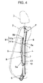
- Figure 4 is a side view showing details of the seatback frame shown in Figure 3;
- Figure 5 is an explanatory side view showing deflection of the seatback frame;
- Figure 6 a front view of a seatback frame structure in accordance with another preferred embodiment of the present invention;
- Figure 7 a side view of the seatback frame structure shown in Figure 6;
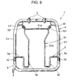
- Figure 8 a front view of a seatback frame structure in accordance with another preferred embodiment of the present invention;
- Figure 9 a side view of the seatback frame structure shown in Figure 8;
- Figure 10 a front view of a seatback frame structure in accordance with another preferred embodiment of the present invention;
- Figure 11 a side view of the seatback frame structure shown in Figure 10;
- Figure 12 a front view of a seatback frame structure in accordance with still another preferred embodiment of the present invention;
- Figure 13 a side view of the seatback frame structure shown in Figure 12;
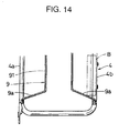
- Figure 14 a front view of a lower part of a seatback frame structure in which base frame sections are bent outward down; and
- Figure 15 a front view of a lower part of a seatback frame structure in which base frame sections are bent outward up.
-
- Referring to the drawings in detail, in particular to Figures 1 to 4 showing a vehicle seat S with a seatback in accordance with a preferred embodiment of the present invention, the vehicle seat S comprises a
seat cushion 1, aseatback 2 and ahead rest 3. Theseatback 2, against which a person P sitting on the vehicle seat S leans on, has aseatback frame 4 made from a pipe installed therein which is configured so as to provide the seatback with a required structural stiffness. Theseatback frame 4 has oppositeside frame sections seatback 2, theseatback frame 4, which is made of a single pipe member, has a configuration forming theside sections lower section 4d and upper sections 4c at which theseatback frame 4 is connected. Each upper section 4c is provided with amount 5 welded or otherwise secured thereto for receiving ahead rest pole 3a extending from thehead rest 3. Theseatback frame 4 is provided with abracket 6 welded or otherwise secured to lower end of one of theside sections left side section 4a next to a passenger seat (not shown) in this embodiment, for connecting theseatback 2 to theseat cushion 1 so as to allow theseatback 2 to turn relatively to theseat cushion 1. Theseatback frame 4 is further provided with anattachment 7 secured to the middle part of another side section, namely theright side section 4b next to a door, for attaching a side air bag unit B. A lower orprimary wire frame 9 and an upper orsubsidiary wire frame 8 are laid between theside sections subsidiary wire frame 8 is welded or otherwise secured to theopposite side sections 4b of theseatback frame 4 at an approximate average height of shoulder blades and deformed downward back fromopposite ends 8b so as to form amiddle section 8a extending along a specified horizontal length. Theprimary wire frame 9 comprises three sections, namely oppositehorizontal base sections 9a extending from the sidevertical sections back support section 91 extending upward in front of and across over thehorizontal middle section 8a of thesubsidiary wire frame 8. Theback support section 91 comprisesvertical sections 91b extending from the oppositehorizontal base sections 9a, respectively, to the average height of shoulder blades and ahorizontal top section 91a extending between thevertical sections 91b. Each of thevertical section 91b at its upper part is slightly deformed backward and shaped so as to extend along the backbone of a person P. Each of thevertical section 91b at its free end is bent downward at a right angle so as to be inserted and fixed in acylindrical support 10 which is welded or otherwise secured to the sidevertical section seatback frame 4. Theprimary wire frame 9 is configured to have a distance of approximately 50 to 150 mm between the oppositevertical sections 91b. If the distance between the oppositevertical sections 91b is less than approximately 50 mm, theback support sections 91 of theprimary wire frame 9 are positioned correspondingly to dendrites at opposite sides of the backbone of a person P sitting on the vehicle seat S which are sensitive to alien substances, so as to cause an enhanced feeling of alien substance at the back of the person P. On the other hand, if the distance between the oppositevertical sections 91b is greater than approximately 150 mm, theprimary wire frame 9 provides the person P with a feeling of uncomfortable support at the back. - According to the seatback frame structure F thus configured, when a person P sits on the vehicle seat S, the
seatback frame 4 causes a deformation such as shown in Figure 5 which provides the person with a comfortable sitting feeling. Specifically, when a person P sits on the vehicle seat S, theback support section 91 of theprimary wire frame 9 elastically deforms so as to incline backward about thehorizontal base sections 9a as a supporting point until theback support section 91 at its upper part is stopped by thehorizontal middle section 8a of thesubsidiary wire frame 8 and held in the inclined position as shown by a double-dot broken line in Figure 5. In other words, thesubsidiary wire frame 8 is operative to restrict backward deflection of theprimary wire frame 9 and is referred to as a deflection restricting member. By means of the deformation of theback support section 91 in this fashion, theprimary wire frame 9 continuously supports over the back of the person P and co-operates with thesubsidiary wire frame 8 so as to securely support the shoulder blade of the person P in a wide extent at opposite sides thereof, which improves the continuity of support of theseatback 2, secures supporting rigidity of theseatback 2 against the upper half of the body of the person P, and eliminates a feeling of alien substance at the back of the person P. Furthermore, theprimary wire frame 9 which extends from the sidevertical sections seatback frame 4 at a height of the of lumbar vertebra of the person P is hard to deform backward even when receiving a load from the person P, so as to securely support the lumbar of the person P. - As described above, the
seatback 2 having the seatback frame structure F installed therein elastically deforms backward at a part corresponding in position to the shoulder blade of a person P sitting on theseat 2 with an effect of providing the person P with a feeling of backward movement and securely supports the person P at his or her lumbar without exerting an influence of the deformation of theback support section 91 on the person P along his or her lumbar vertebra, so as to support the back of the person P along the S-shaped backbone. The seatback frame structure F which includes thesubsidiary wire frame 8 and theprimary wire frame 9 only other than theseatback frame 4 meets a demand for light-weight and adaptability to automatic assembling and provides a large space for installing a side air bag unit. In the case of a reclining seat, the seatback reclined horizontally is prevented from damage even when it is ridden thereon by a person because the inverselyU-shaped support section 91 strictly causes only a limited backward deformation. - Referring to Figures 6 and 7 show a seatback frame structure F in accordance with another embodiment of the present invention which has a
primary wire frame 9 different from that shown in Figures 3 and 4. As shown, theprimary wire frame 9 has a U-shaped lowerback support section 92 extending to a position corresponding to a coccyx of a person P sitting on from and between eachhorizontal base section 9a and an inversely U-shaped upperback support section 91. The lowerback support section 92 comprises avertical section 92c extending from ahorizontal base section 9a, avertical section 92b extending from, or forming part of, thevertical section 91b of the upperback support section 91 and ahorizontal section 92a extending thevertical sections vertical section 91b of the upperback support section 91 and thevertical section 92b of the lowerback support section 92 form a swelling 30, namely a lumbar support section, directed forward at their juncture which is in a vertical position corresponding to a lumbar vertebra of the person P siting on as shown in Figure 7. - According to the seatback frame structure F thus configured, in addition to the same effect as the
seatback 2 shown in Figures 3 and 4, the seatback with the seatback structure F installed therein supports the back of a person P at opposite sides of the backbone from the shoulder blade to part near the coccyx without a break, which eliminates a feeling of alien substrate at the back. Furthermore, theseatback 2 prevents the person P sitting on the vehicle seat S from getting pore sitting posture due to a backward positional change of the buttocks of the person P on theseat cushion 3. The lumbar support section 30 which is formed between and swelled forward from the upperback support section 91 and the lowerback support section 92 certainly support the lumbar of the person P sitting on even when the upperback support section 91 and the lowerback support section 92 elastically deform backward due to the person's weight. Theprimary wire frame 9 increasingly vary the seatback stiffness from the lower part to the upper part, so as to provide easily the person P sitting on the seat with appropriate siting posture and realise a low cost seat. - Referring to Figures 8 and 9 show another seatback frame structure F which has a pair of tension coil springs 101 in place of the
subsidiary wire frame 8 as a deflection restricting member. As shown, the seatback frame structure F has ansubsidiary wire frame 9 which comprises an inversely U-shaped upperback support section 91 and U-shaped lowerback support sections 92. The upperback support section 91 comprisesvertical sections 91b extending from lowerback support sections 92, respectively, and a horizontaltop section 91a extending between tops of thevertical sections 91b and are configured so to provide a wide space at its upper part so as to securely support the shoulder blade of the person P in a wide extent even though there is no upper wire support provided therein. The tension springs 101 are mounted between upper corners of the upperback support section 91 andcorner brackets 4d secured to upper corners of the upperback support section 91. - According to the seatback frame structure F thus configured, although the
seatback 2 needs a little increased number of parts, it provides almost the same results as those described above. Furthermore, thetension spring 101 for suspending the upperback support section 91 from theseatback frame 4 is replaced with another tension spring having a different spring tension so as to change backward deflection of the upperback support section 91, which is always desirable to provide theseatback 2 meeting a demand of a person P who sits on the vehicle seat S. - Referring to Figures 10 and 11 show a seatback frame structure F in accordance with another embodiment of the present invention which has a wave-formed
wire spring 110 as a deflection restricting member in place of thesubsidiary wire frame 8. As shown, the wave-formedwire spring 110 is secured at opposite ends to oppositeside frame sections seatback frame 4, respectively. An upperback support section 91 atvertical sections 91b is secured to the wave-formedwire spring 110. Theupper support section 91, which has just the same configuration as that of the seatback frame F shown in Figure 6 and 7, co-operates with the wave-formedwire spring 110 to support the upper back of a person P sitting on the vehicle seat S. - According to the seatback frame structure F thus configured, the
seatback 2 provides the same results as those previously described, besides theseatback 2 meeting a demand of a person P who sits on the vehicle seat S can be provided by replacing the wave-formedwire spring 110 with one having a different spring strength so as to change backward deflection of the upperback support section 91. The wave-formedwire spring 110 does not need a space thick as much as the coil tension springs 101 shown in Figures 8 and 9, so that theseatback 2 can be thin. - Referring to Figures 12 and 13 show a seatback frame structure F in accordance with still another embodiment of the present invention in which a
primary wire frame 9 is connected to ansubsidiary wire frame 8 so as to provide theprimary wire frame 9 with a froward tension in a state where no person sits on a vehicle seat S with an effect of increasing stiffness of theprimary wire frame 9 against backward deflection and decreasing backward deflection of theprimary wire frame 9. Specifically, theprimary wire frame 9 at its horizontaltop section 91a is coupled to amiddle section 8a of thesubsidiary wire frame 8 by means of an elasticity exerting member, for example acoupler 120 such as made of an unwoven fabric that is hard to expand and causes less frictional sounds. Theprimary wire frame 9 is installed to aseatback frame 4 with a slight forward deflection as shown by a double-dotted broken line in Figure 13 before it is coupled to thesubsidiary wire frame 8. When coupling theprimary wire frame 9 to thesubsidiary wire frame 8, theprimary wire frame 9 is pulled back and then coupled to thesubsidiary wire frame 8 by theunwoven fabric coupler 120, so as to be provided with forward elasticity. As a result, theprimary wire frame 9 is provided with increased stiffness against backward deflection during supporting the back of the person P. - According to the seatback frame structure F thus configured, the
seatback 2 provides the same results as those shown in Figures 3 to 5 and Figures 6 and 7. Furthermore, because theprimary wire frame 9 is pre-tensioned forward, the upper part of theseatback 2 is provided with ensured stiffness against a load applied thereto without providing theprimary wire frame 9 with increased stiffness. Utilising theunwoven fabric coupler 120 in place of the tension springs 101 or the wave-formedwire spring 110 prevents the upperback support section 91 from abutting against thesubsidiary wire frame 8 and causing noises due to friction with thesubsidiary wire frame 8. - The
primary wire frame 9 may be configured in fitting structure as shown in Figure 14 or 15. - As shown in Figure 14, a
primary wire frame 9 has aback support section 91 which comprises oppositevertical sections 91 extending fromopposite base sections 9a, respectively. Eachbase section 9a extends outward down from thevertical section 91 so as to provide a broad space on an side of eachside frame section 4a, which is desirable for increasing the degree of freedom of laying out a side air bag unit B. - As shown in Figure 15, a
primary wire frame 9 has aback support section 91 extending near a position corresponding to a coccyx of a person P sitting on the seat S which comprises oppositevertical sections 91 extending fromopposite base sections 9a extending outward up, respectively. Aseatback 2 having theprimary wire frame 9 thus configured provides support of the back of a person sitting on the seat from the near coccyx position to the shoulder blade even though it is not provided with a lower back support section like those shown in Figure 6, 8, 10 or 12. While a person P leans on theseatback 2, theprimary wire frame 9 deforms continuously from its lower part to its upper part, so that theseatback 2 at its middle section can support the back of the person P continuously to the near coccyx position. Furthermore, theseatback 2 at its opposite sides increases supporting rigidity against the lumbar of the person by means of theinclined base sections 9a. - The seatback frame is not limited to those of the preferred embodiments and may be modified and constructed by a single wire frame as long as comprising an lower back support section and base sections that work as a lumbar support. Further, the seatback may be utilised for seats other than a vehicle seat.
Claims (11)
- A seatback frame structure (F) having a generally rectangular seatback frame (4) which comprises opposite side frame sections (4a) extending vertically along opposite sides of a seatback (2) of a seat (S) and which is installed in said seatback (2), characterised by:
a wire frame (9) comprising a pair of base frame sections (9a) extending between and secured to lower parts of said opposite side frame sections (4a), respectively, and an upward extending support frame section (91) extending upward from said base frame sections (9a) and elastically deflectable backward with respect to said base frame sections (9a) . - A seatback frame structure (F) as defined in claim 1, wherein said wire frame (9) further comprises downward extending support frame sections (92) disposed between said base frame sections (9a) and said upward extending support frame section (91), respectively, and extending downward from said base frame sections (9a) and elastically deflectable backward with respect to said base frame sections (9a).
- A seatback frame structure (F) as defined in claim 1 or 2, wherein said base frame sections (9a) extend at a height corresponding to a lumbar vertebra of a person (P) who sits on the seat (S) and said upward extending support frame section (91) extends upward from said base frame sections (9a) to a height corresponding to shoulder blades of the person (P).
- A seatback frame structure (F) as defined in any one of claims 1 to 3, wherein said wire frame (9) further comprises downward extending support frame sections (92) disposed between said base frame sections (9a) and said upward extending support frame section (91), respectively, so as to extend downward to said height corresponding to said lumbar vertebra from said base frame sections (9a) and elastically deflectable backward with respect to said base frame sections (9a).
- A seatback frame structure (F) as defined in any one of claims 1 to 4, and further comprising a deflection restricting member (8, 101, 110) operative to restrict said wire frame (9) to a specified backward deflection.
- A seatback frame structure (F) as defined in claim 5, wherein said deflection restricting member (8) is disposed behind said upward extending support frame section (91) of said wire frame (9) and comprises a subsidiary wire frame (8) extending between and secured to upper parts of said opposite side frame sections (4a), respectively, so as to cross over said upward extending support frame section (91) of said wire frame (9).
- A seatback frame structure (F) as defined in claim 5, wherein said deflection restricting member (101, 110) comprises an elastic member operative to suspend said upward extending support frame section (91) from said generally rectangular seatback frame (4).
- A seatback frame structure (F) as defined in any one of claims 1 to 7, wherein said base frame section (9a) extends horizontally.
- A seatback frame structure (F) as defined in any one of claims 1-8, and further comprising elasticity exerting member (120) operative to provide said wire frame (9) with forward elasticity and to allow said upward extending support frame section (91) to deflect only backward.
- A seatback frame structure (F) as defined in claim 9, wherein said elasticity exerting member (120) fixedly couples said wire frame (9) at said upward extending support frame section (91) to said generally rectangular seatback frame (4).
- A seatback frame structure (F) as defined in claim 2 or 4, wherein said wire frame (9) is configured so as to form a swelling (93) between said upward extending support frame section (91) and said downward extending support section (92), said swelling (93) being directed forward at a height corresponding to a lumbar vertebra of a person (P) who sits on the seat.
Applications Claiming Priority (2)
| Application Number | Priority Date | Filing Date | Title |
|---|---|---|---|
| JP16504799 | 1999-06-11 | ||
| JP16504799A JP4182592B2 (en) | 1999-06-11 | 1999-06-11 | Seat back structure |
Publications (3)
| Publication Number | Publication Date |
|---|---|
| EP1059196A2 true EP1059196A2 (en) | 2000-12-13 |
| EP1059196A3 EP1059196A3 (en) | 2003-08-20 |
| EP1059196B1 EP1059196B1 (en) | 2007-04-04 |
Family
ID=15804836
Family Applications (1)
| Application Number | Title | Priority Date | Filing Date |
|---|---|---|---|
| EP00304888A Expired - Lifetime EP1059196B1 (en) | 1999-06-11 | 2000-06-09 | Frame structure for a seatback of a seat |
Country Status (4)
| Country | Link |
|---|---|
| US (1) | US6371561B1 (en) |
| EP (1) | EP1059196B1 (en) |
| JP (1) | JP4182592B2 (en) |
| DE (1) | DE60034176T2 (en) |
Cited By (1)
| Publication number | Priority date | Publication date | Assignee | Title |
|---|---|---|---|---|
| CN102700445A (en) * | 2012-05-19 | 2012-10-03 | 东莞市凌锐汽车零部件有限公司 | Electric seat lumbar support |
Families Citing this family (11)
| Publication number | Priority date | Publication date | Assignee | Title |
|---|---|---|---|---|
| DE202005001624U1 (en) * | 2005-02-02 | 2005-04-07 | Schukra Geraetebau Ag Berndorf | Lordosis support for a seat especially in a motor vehicle has two long sections with fingers of plastic sections extending across between and beyond them |
| US7284800B2 (en) * | 2005-12-30 | 2007-10-23 | Tachi-S Co., Ltd. | Seat back frame for automotive seat |
| JP4952306B2 (en) * | 2007-03-07 | 2012-06-13 | トヨタ紡織株式会社 | Seat back |
| US7527334B2 (en) * | 2007-06-18 | 2009-05-05 | Ford Global Technologies, Llc | Automotive seat reclining system |
| KR100999143B1 (en) * | 2008-04-21 | 2010-12-08 | 현대자동차주식회사 | Rear seatback strength reinforcement mechanism |
| DE102008061750A1 (en) | 2008-12-12 | 2010-06-17 | GM Global Technology Operations, Inc., Detroit | Supporting frame for backrest of motor vehicle seat, has two crosspieces, which are connected together over upper cross stud, where crosspieces are formed in S-shape manner in side view |
| DE102009014335A1 (en) * | 2009-03-21 | 2010-09-23 | Dr. Ing. H.C. F. Porsche Aktiengesellschaft | vehicle seat |
| DE102010010188B4 (en) * | 2010-03-01 | 2011-11-10 | Keiper Gmbh & Co. Kg | Vehicle seat, in particular motor vehicle seat |
| US9738194B2 (en) * | 2013-04-08 | 2017-08-22 | Ts Tech Co., Ltd. | Vehicle seat and seat frame for same |
| US10556529B2 (en) | 2013-10-07 | 2020-02-11 | Adient Luxembourg Holding S.a.r.l. | Seat structure |
| JP6863234B2 (en) * | 2017-10-31 | 2021-04-21 | トヨタ自動車株式会社 | Vehicle seat |
Citations (1)
| Publication number | Priority date | Publication date | Assignee | Title |
|---|---|---|---|---|
| JPH1085079A (en) | 1996-09-19 | 1998-04-07 | Mazda Motor Corp | Seat back structure |
Family Cites Families (11)
| Publication number | Priority date | Publication date | Assignee | Title |
|---|---|---|---|---|
| US4725095A (en) * | 1986-07-11 | 1988-02-16 | Johnson Service Company | Vehicle seat with mechanical lumbar support having two degrees of freedom |
| US5101811A (en) * | 1989-09-25 | 1992-04-07 | Sumner Brunswick | Fitted seating apparatus and manufacture |
| GB9209229D0 (en) * | 1992-04-29 | 1992-06-17 | Youndflex S A | Improvements in and relating to seat arrangements providing adjustable lumbar support |
| JPH07257248A (en) * | 1994-03-18 | 1995-10-09 | Aisin Seiki Co Ltd | Folded seat for vehicle |
| US5509716A (en) * | 1994-11-08 | 1996-04-23 | General Motors Corporation | Vehicle seat with perimeter frame and pelvic catcher |
| JPH0910066A (en) * | 1995-06-27 | 1997-01-14 | Araco Corp | Lumber support device for vehicle seats |
| JP3564809B2 (en) * | 1995-08-08 | 2004-09-15 | アイシン精機株式会社 | Lumber support device |
| JP3397952B2 (en) * | 1995-09-18 | 2003-04-21 | デルタ工業株式会社 | Lumbar support structure for automotive seat back |
| US5697670A (en) * | 1996-11-12 | 1997-12-16 | Hoover Universal, Inc. | Vehicle seat |
| DE19800869C1 (en) * | 1998-01-13 | 1999-05-12 | Faure Bertrand Sitztech Gmbh | Spring cushion for motor vehicle |
| US6186594B1 (en) * | 1998-04-07 | 2001-02-13 | Corporation De L'ecole Polytechnique | Flexible contour wheelchair backrest |
-
1999
- 1999-06-11 JP JP16504799A patent/JP4182592B2/en not_active Expired - Fee Related
-
2000
- 2000-06-09 EP EP00304888A patent/EP1059196B1/en not_active Expired - Lifetime
- 2000-06-09 DE DE60034176T patent/DE60034176T2/en not_active Expired - Lifetime
- 2000-06-09 US US09/590,134 patent/US6371561B1/en not_active Expired - Lifetime
Patent Citations (1)
| Publication number | Priority date | Publication date | Assignee | Title |
|---|---|---|---|---|
| JPH1085079A (en) | 1996-09-19 | 1998-04-07 | Mazda Motor Corp | Seat back structure |
Cited By (1)
| Publication number | Priority date | Publication date | Assignee | Title |
|---|---|---|---|---|
| CN102700445A (en) * | 2012-05-19 | 2012-10-03 | 东莞市凌锐汽车零部件有限公司 | Electric seat lumbar support |
Also Published As
| Publication number | Publication date |
|---|---|
| JP2000350635A (en) | 2000-12-19 |
| EP1059196B1 (en) | 2007-04-04 |
| DE60034176D1 (en) | 2007-05-16 |
| EP1059196A3 (en) | 2003-08-20 |
| US6371561B1 (en) | 2002-04-16 |
| DE60034176T2 (en) | 2007-12-20 |
| JP4182592B2 (en) | 2008-11-19 |
Similar Documents
| Publication | Publication Date | Title |
|---|---|---|
| JP5365167B2 (en) | Vehicle seat cushion | |
| US7290837B2 (en) | Cushion plate for vehicle seat | |
| US9073466B2 (en) | Vehicle seat | |
| JP7469686B2 (en) | Sheet | |
| US7926872B2 (en) | Vehicle seat | |
| CN1822781B (en) | Comfort surface for seating | |
| CN103889273B (en) | Seats, especially office chairs | |
| EP1059196B1 (en) | Frame structure for a seatback of a seat | |
| CN105593058A (en) | seat structure | |
| JP2009101137A (en) | Seat backs for vehicular seats | |
| JP5561398B2 (en) | Vehicle seat cushion | |
| JP3008492B2 (en) | Seat device | |
| JP2002028044A (en) | Seat structure | |
| JP2000175761A (en) | Vehicle seat cushion | |
| JP3397952B2 (en) | Lumbar support structure for automotive seat back | |
| CN214548396U (en) | Main pipe chair and chair back structure thereof | |
| JP6825970B2 (en) | Load-bearing members for chairs and chairs | |
| JP7635662B2 (en) | Seat device | |
| JP7832865B2 (en) | Back support device and vehicle seat | |
| CN217547602U (en) | Chair | |
| CN221635366U (en) | Chair back structure applied to office chair | |
| JPH0716361Y2 (en) | Seat cushion structure for vehicle seats | |
| JP3102864U (en) | Half-cut cushion sheet | |
| JP2589107Y2 (en) | Vehicle seat | |
| JP2024023124A (en) | vehicle seat |
Legal Events
| Date | Code | Title | Description |
|---|---|---|---|
| PUAI | Public reference made under article 153(3) epc to a published international application that has entered the european phase |
Free format text: ORIGINAL CODE: 0009012 |
|
| AK | Designated contracting states |
Kind code of ref document: A2 Designated state(s): AT BE CH CY DE DK ES FI FR GB GR IE IT LI LU MC NL PT SE |
|
| AX | Request for extension of the european patent |
Free format text: AL;LT;LV;MK;RO;SI |
|
| PUAL | Search report despatched |
Free format text: ORIGINAL CODE: 0009013 |
|
| AK | Designated contracting states |
Designated state(s): AT BE CH CY DE DK ES FI FR GB GR IE IT LI LU MC NL PT SE |
|
| AX | Request for extension of the european patent |
Extension state: AL LT LV MK RO SI |
|
| RIC1 | Information provided on ipc code assigned before grant |
Ipc: 7A 47C 7/46 B Ipc: 7B 60N 2/64 A Ipc: 7B 60N 2/66 B Ipc: 7B 60N 2/70 B |
|
| 17P | Request for examination filed |
Effective date: 20031223 |
|
| AKX | Designation fees paid |
Designated state(s): DE ES FR GB IT |
|
| GRAP | Despatch of communication of intention to grant a patent |
Free format text: ORIGINAL CODE: EPIDOSNIGR1 |
|
| GRAS | Grant fee paid |
Free format text: ORIGINAL CODE: EPIDOSNIGR3 |
|
| GRAA | (expected) grant |
Free format text: ORIGINAL CODE: 0009210 |
|
| AK | Designated contracting states |
Kind code of ref document: B1 Designated state(s): DE ES FR GB IT |
|
| REG | Reference to a national code |
Ref country code: GB Ref legal event code: FG4D |
|
| REF | Corresponds to: |
Ref document number: 60034176 Country of ref document: DE Date of ref document: 20070516 Kind code of ref document: P |
|
| PG25 | Lapsed in a contracting state [announced via postgrant information from national office to epo] |
Ref country code: ES Free format text: LAPSE BECAUSE OF FAILURE TO SUBMIT A TRANSLATION OF THE DESCRIPTION OR TO PAY THE FEE WITHIN THE PRESCRIBED TIME-LIMIT Effective date: 20070715 |
|
| EN | Fr: translation not filed | ||
| PLBE | No opposition filed within time limit |
Free format text: ORIGINAL CODE: 0009261 |
|
| STAA | Information on the status of an ep patent application or granted ep patent |
Free format text: STATUS: NO OPPOSITION FILED WITHIN TIME LIMIT |
|
| 26N | No opposition filed |
Effective date: 20080107 |
|
| GBPC | Gb: european patent ceased through non-payment of renewal fee |
Effective date: 20070704 |
|
| PG25 | Lapsed in a contracting state [announced via postgrant information from national office to epo] |
Ref country code: IT Free format text: LAPSE BECAUSE OF FAILURE TO SUBMIT A TRANSLATION OF THE DESCRIPTION OR TO PAY THE FEE WITHIN THE PRESCRIBED TIME-LIMIT Effective date: 20070404 Ref country code: FR Free format text: LAPSE BECAUSE OF FAILURE TO SUBMIT A TRANSLATION OF THE DESCRIPTION OR TO PAY THE FEE WITHIN THE PRESCRIBED TIME-LIMIT Effective date: 20071130 |
|
| PG25 | Lapsed in a contracting state [announced via postgrant information from national office to epo] |
Ref country code: GB Free format text: LAPSE BECAUSE OF NON-PAYMENT OF DUE FEES Effective date: 20070704 |
|
| PG25 | Lapsed in a contracting state [announced via postgrant information from national office to epo] |
Ref country code: FR Free format text: LAPSE BECAUSE OF FAILURE TO SUBMIT A TRANSLATION OF THE DESCRIPTION OR TO PAY THE FEE WITHIN THE PRESCRIBED TIME-LIMIT Effective date: 20070404 |
|
| PGFP | Annual fee paid to national office [announced via postgrant information from national office to epo] |
Ref country code: DE Payment date: 20150602 Year of fee payment: 16 |
|
| REG | Reference to a national code |
Ref country code: DE Ref legal event code: R119 Ref document number: 60034176 Country of ref document: DE |
|
| PG25 | Lapsed in a contracting state [announced via postgrant information from national office to epo] |
Ref country code: DE Free format text: LAPSE BECAUSE OF NON-PAYMENT OF DUE FEES Effective date: 20170103 |