EP1058487A1 - System for and method of operating a discharge lamp - Google Patents
System for and method of operating a discharge lamp Download PDFInfo
- Publication number
- EP1058487A1 EP1058487A1 EP00103112A EP00103112A EP1058487A1 EP 1058487 A1 EP1058487 A1 EP 1058487A1 EP 00103112 A EP00103112 A EP 00103112A EP 00103112 A EP00103112 A EP 00103112A EP 1058487 A1 EP1058487 A1 EP 1058487A1
- Authority
- EP
- European Patent Office
- Prior art keywords
- discharge lamp
- arc
- lamp
- power
- operating
- Prior art date
- Legal status (The legal status is an assumption and is not a legal conclusion. Google has not performed a legal analysis and makes no representation as to the accuracy of the status listed.)
- Granted
Links
- 238000000034 method Methods 0.000 title claims abstract description 17
- 238000005452 bending Methods 0.000 claims abstract description 16
- 230000001965 increasing effect Effects 0.000 claims abstract description 9
- 230000000694 effects Effects 0.000 claims description 2
- 239000003990 capacitor Substances 0.000 description 4
- 230000000368 destabilizing effect Effects 0.000 description 3
- 238000010586 diagram Methods 0.000 description 3
- 230000000087 stabilizing effect Effects 0.000 description 3
- DGAQECJNVWCQMB-PUAWFVPOSA-M Ilexoside XXIX Chemical compound C[C@@H]1CC[C@@]2(CC[C@@]3(C(=CC[C@H]4[C@]3(CC[C@@H]5[C@@]4(CC[C@@H](C5(C)C)OS(=O)(=O)[O-])C)C)[C@@H]2[C@]1(C)O)C)C(=O)O[C@H]6[C@@H]([C@H]([C@@H]([C@H](O6)CO)O)O)O.[Na+] DGAQECJNVWCQMB-PUAWFVPOSA-M 0.000 description 2
- 230000008878 coupling Effects 0.000 description 2
- 238000010168 coupling process Methods 0.000 description 2
- 238000005859 coupling reaction Methods 0.000 description 2
- 230000001939 inductive effect Effects 0.000 description 2
- QSHDDOUJBYECFT-UHFFFAOYSA-N mercury Chemical compound [Hg] QSHDDOUJBYECFT-UHFFFAOYSA-N 0.000 description 2
- 229910001507 metal halide Inorganic materials 0.000 description 2
- 150000005309 metal halides Chemical class 0.000 description 2
- 229910052708 sodium Inorganic materials 0.000 description 2
- 239000011734 sodium Substances 0.000 description 2
- 230000006641 stabilisation Effects 0.000 description 2
- 238000011105 stabilization Methods 0.000 description 2
- 101001080597 Spinacia oleracea 50S ribosomal protein 5 alpha, chloroplastic Proteins 0.000 description 1
- 238000007792 addition Methods 0.000 description 1
- 239000000919 ceramic Substances 0.000 description 1
- 230000005484 gravity Effects 0.000 description 1
- 238000002347 injection Methods 0.000 description 1
- 239000007924 injection Substances 0.000 description 1
- 229910052753 mercury Inorganic materials 0.000 description 1
- 239000000203 mixture Substances 0.000 description 1
- 230000000737 periodic effect Effects 0.000 description 1
Images


Classifications
-
- H—ELECTRICITY
- H05—ELECTRIC TECHNIQUES NOT OTHERWISE PROVIDED FOR
- H05B—ELECTRIC HEATING; ELECTRIC LIGHT SOURCES NOT OTHERWISE PROVIDED FOR; CIRCUIT ARRANGEMENTS FOR ELECTRIC LIGHT SOURCES, IN GENERAL
- H05B41/00—Circuit arrangements or apparatus for igniting or operating discharge lamps
- H05B41/14—Circuit arrangements
- H05B41/36—Controlling
- H05B41/38—Controlling the intensity of light
-
- H—ELECTRICITY
- H05—ELECTRIC TECHNIQUES NOT OTHERWISE PROVIDED FOR
- H05B—ELECTRIC HEATING; ELECTRIC LIGHT SOURCES NOT OTHERWISE PROVIDED FOR; CIRCUIT ARRANGEMENTS FOR ELECTRIC LIGHT SOURCES, IN GENERAL
- H05B41/00—Circuit arrangements or apparatus for igniting or operating discharge lamps
- H05B41/14—Circuit arrangements
- H05B41/26—Circuit arrangements in which the lamp is fed by power derived from DC by means of a converter, e.g. by high-voltage DC
- H05B41/28—Circuit arrangements in which the lamp is fed by power derived from DC by means of a converter, e.g. by high-voltage DC using static converters
- H05B41/288—Circuit arrangements in which the lamp is fed by power derived from DC by means of a converter, e.g. by high-voltage DC using static converters with semiconductor devices and specially adapted for lamps without preheating electrodes, e.g. for high-intensity discharge lamps, high-pressure mercury or sodium lamps or low-pressure sodium lamps
- H05B41/2881—Load circuits; Control thereof
- H05B41/2882—Load circuits; Control thereof the control resulting from an action on the static converter
- H05B41/2883—Load circuits; Control thereof the control resulting from an action on the static converter the controlled element being a DC/AC converter in the final stage, e.g. by harmonic mode starting
Definitions
- the present invention relates to a system for and method of operating a discharge lamp, and more particularly, to increasing the lamp voltage and power by bending the arc in an arc tube of a discharge lamp to increase the length of the arc.
- a typical High Intensity Discharge (HID) lamp has a fixed lamp voltage load. Under some circumstances, it is desired to deliver to the lamp more power than normal. For example, in some lamp applications it is desired to provide fast lamp warm-up.
- the amount of power delivered to an HID lamp is the product of the lamp voltage and the current supplied by the ballast.
- the current available from a conventional electronic ballast is typically limited by its current carrying switching components. Therefore, using such a current limited ballast with a conventional fixed lamp voltage load, it has not been possible heretofore to supply more power to the lamp.
- the current supplied by the ballast can be increased by providing higher current switching components, higher current switching components are more expensive than conventional current limited ballasts.
- the present invention increases lamp voltage, using a conventional current limited ballast, by bending the arc in the arc tube to increase the length of the arc.
- arc length can be increased by injecting acoustic frequencies into the waveform of the power supplied to the lamp to bend the arc.
- Another object of the present invention is to obviate the disadvantages of the prior art by providing an improved method of and system for increasing lamp voltage using a current limited ballast.
- Yet another object of the present invention is to provide an improved method of and system for operating a discharge lamp by supplying more power to a fixed voltage lamp load.
- a further object of the present invention is to use acoustic frequencies to increase power input when operating a discharge lamp.
- a discharge lamp is supplied with an input waveform to power the lamp, and the arc formed within the discharge lamp is bent to lengthen the arc and thereby increase lamp power.
- acoustic frequencies are injected into the power waveform supplied to the discharge lamp to bend the arc and thereby increase lamp power.
- FIG. 1 illustrates a system 10 in accordance with one embodiment of the present invention for the operation of a discharge lamp 12.
- the system 10 is provided for pulse-exciting a high intensity discharge lamp 12 in a manner which will bend the arc of the arc tube 14 in the lamp 12 to increase arc length thereby increasing lamp voltage and power.
- system 10 includes a function generator and power amplifier combination.
- a function generator 16 is provided coupled to a power amplifier 18.
- a typical function generator 16 which can be employed is a Model No. F34, manufactured by IEC.
- a typical power amplifier 18 which can be used is a Model No. 1140LA, manufactured by ENI.
- the system 10 includes a dc power supply and resistor ballast combination.
- dc power supply 20 is coupled to a resistor 22 providing a series dc power supply and resistor ballast combination.
- a typical dc power supply 20 which can be used is a Model No. HP6035A, manufactured by Hewlett Packard.
- the resistor 22 is a conventional 25 Ohm non-inductive power resistor.
- a typical resistor 22 which can be used is a Model No. Pecos TC100PA10R00J, manufactured by Ohmite.
- the output of the ballast combination is capacitively coupled to the output of the function generator/power amplifier combination to provide a dc voltage which is fed to an H-bridge commutator 24.
- the capacitive coupling is provided by a resistor 26 and capacitor 28.
- the resistor 26 is a conventional 30 Ohm non-inductive power resistor.
- a typical resistor 26 which can be used is a Model No. Pecos TC100PA10R00J, manufactured by Ohmite.
- the capacitor 28 is a conventional 1 ⁇ F capacitor.
- a typical capacitor 28 which can be used is a Model No. 1 ⁇ F/K630V, manufactured by Sprague.
- the H-bridge commutator 24 is operatively coupled to the lamp 12 through a conventional in-rush limiting resistor 30.
- a typical resistor 30 which can be used is a Model No. CL40, manufactured by Panasonic.
- a pulse generator 32 is coupled to the H-bridge commutator 24 for setting the timing of the H-bridge commutator.
- a typical pulse generator 32 which can be used is a Model No. DG535, manufactured by Stanford Research.
- the system 10 provides one embodiment of the present invention useful in controlling a lamp system by (a) supplying a discharge lamp with an input waveform to power the discharge lamp, and (b) bending the arc within the discharge lamp to increase arc length to increase lamp power.
- bending of the arc in arc tube 14 is effected by injecting acoustic frequencies into the power waveform supplied to the discharge lamp to lengthen the arc as discussed hereinafter.
- the function generator 16 is tuned to low acoustic frequencies.
- the specific low frequencies which cause the increased lamp voltage will vary depending upon lamp features such as the dimensions and geometry of the arc tube and the temperature and composition of the enclosed fill. In other words, the frequencies will vary from lamp to lamp as one or more of these features vary.
- acoustic frequencies may range between about 1kHz for general lighting-type lamps to about 200 kHz for lamps such as automobile head lamps.
- the arc may be caused to bend to increase arc length and lamp voltage in accordance with the present invention by imposing the particular acoustic frequency components in the power waveform applied to the lamp.
- the function generator 16 is tuned to low acoustic frequencies to excite the destabilizing longitudinal mode of the arc in the arc tube 14 of the discharge lamp 12.
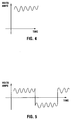
- a ripply dc voltage as illustrated in FIG. 4 will be provided at an input of the H-bridge commutator 24 by capacitively coupling the power amplified acoustic waveform provided by the tuned function generator 16 and power amplifier 18 to the output of the ballast combination 20, 22.
- the H-bridge commutator 24 will produce an acoustically modulated square wave ballast waveform as illustrated in FIG. 5 which will be fed to the lamp 12 through the resistor 30 which provides the conventional in-rush limit.
- FIGS. 2A and 2B An example of the H-bridge commutator 24 is illustrated in FIGS. 2A and 2B (the component values for FIGS. 2A and 2B are listed in Table I).
- FIG. 3 An example of a dc circuit supply for such commutator is illustrated in FIG. 3 (the component values for FIG. 3 are listed in Table II).
- Lamp 12 includes a 400 Watt arc tube 14. Such a lamp requires 3 amps to warm-up to full operation.
- the ballast illustrated in FIG. 1 was powered to 2.5 amps in a conventional manner using the dc power supply 20. Although it was possible to ignite the lamp 12, 2.5 amps was not sufficient for the lamp to operate in a satisfactory manner. In particular, at 2.5 amps the lamp voltage would only reach 35 volts, thereby providing only 75 watts into the lamp. In operating the lamp in this manner, the lamp would not warm up enough to come up to full power.
- the function generator 16 was then tuned to sweep from 8.5 kHz to 12 kHz, and the current limit was set to 2 amps. Operating in this manner, the destabilizing mode of the arc in the arc tube 14 was excited. The arc snaked and was visibly bent to such an extent that it actually bowed out to the wall of the arc tube. Lamp voltage increased to 75 volts, the actual lamp current being measured at 2.2 amps. The additional 0.2 amps current was due to the power amplifier 18.
- the 400 Watt lamp 12 was started and operated at full power using a ballast powered by the dc power supply 20 which was limited to 2 amps. This could not be accomplished when it was attempted to operate the lamp 12 in a conventional manner at 2.5 amps.
- the present invention is particularly applicable to HID lamps having electronic ballast systems, and electronic additions to magnetic ballast systems, including, without limitation, high pressure sodium, mercury and metal halide lamps, having low to high wattage.
- bending of the arc in the arc tube to increase length of the arc and therefore lamp power may be accomplished by, without limitation, the use of magnetic fields, the use of additional electrodes and the like.
- an arc tube having a size and geometry which will accommodate sufficient arc bending caused by natural convection in the lamp during start up may be provided in combination with conventional means to subsequently straighten the arc when the lamp is at full power.
Landscapes
- Engineering & Computer Science (AREA)
- Power Engineering (AREA)
- Circuit Arrangements For Discharge Lamps (AREA)
- Sorption Type Refrigeration Machines (AREA)
Abstract
Description
- The present invention relates to a system for and method of operating a discharge lamp, and more particularly, to increasing the lamp voltage and power by bending the arc in an arc tube of a discharge lamp to increase the length of the arc.
- Generally, a typical High Intensity Discharge (HID) lamp has a fixed lamp voltage load. Under some circumstances, it is desired to deliver to the lamp more power than normal. For example, in some lamp applications it is desired to provide fast lamp warm-up. The amount of power delivered to an HID lamp is the product of the lamp voltage and the current supplied by the ballast. The current available from a conventional electronic ballast is typically limited by its current carrying switching components. Therefore, using such a current limited ballast with a conventional fixed lamp voltage load, it has not been possible heretofore to supply more power to the lamp. Although the current supplied by the ballast can be increased by providing higher current switching components, higher current switching components are more expensive than conventional current limited ballasts. The present invention increases lamp voltage, using a conventional current limited ballast, by bending the arc in the arc tube to increase the length of the arc. For example, arc length can be increased by injecting acoustic frequencies into the waveform of the power supplied to the lamp to bend the arc.
- Bending the arc to increase its length is contrary to conventional treatment of the arc in an arc tube of a discharge lamp. In particular, in conventional lamp applications provided heretofore, whenever efforts have been made to influence the arc, such efforts have involved straightening or otherwise stabilizing and centering the arc. For example, U.S. patent no. 5,134,345 issued on 28 July 1992 to El-Hamamsy et al. illustrates a method of detecting arc instabilities in an HID lamp and changing the drive frequencies that cause them thereby avoiding acoustic frequencies that cause destabilizing phenomena.
- In U.S. patent no. 5,306,987 issued on 26 April 1994 to Dakin et al. reference is made to stabilization of HID lamps by modulating the drive signal with acoustic resonant band frequencies. A similar method of centering the arc in discharge lamps is illustrated in U.S. patent no. 5,198,727 which issued on 30 March 1993 to Allen et al.. This patent illustrates centering the arc by the "acoustic perturbations" induced by the frequency of the drive signals. Such acoustic perturbations compel the gas or vapor movement patterns within the arc tube to counter the gravity-induced convection.
- U.S. patent no. 5,684,367 which issued on 4 November 1997 to Moskowitz et al. illustrates a system for and method of operating a discharge lamp, and in particular, of stabilizing and controlling the characteristics of discharge lamps by amplitude-modulating the input AC power wave with a periodic waveform and/or pulse wave to control stabilization and color characteristics. This patent is commonly owned with the instant application and is incorporated herein by reference.
- In U.S. patent no. 5,047,695 which issued on 10 September 1991 to Allen et al., a method and ballast circuit is illustrated for operating fluorescent, mercury vapor, sodium and metal halide lamps in a DC mode. Power modulation for creating acoustic pressure waves for arc straightening is referred to in this patent. The lamp illustrated therein is operated with a selectable amount of ripple imposed to provide for acoustically straightening the arc between the lamp electrodes. A related patent is the aforementioned 5,198,727 patent.
- All of the foregoing patents relate to straightening or otherwise stabilizing and centering the arc in an arc tube in a discharge lamp. In contrast, the present inventors have developed a new method and system for operating a discharge lamp wherein more power may be supplied to a fixed lamp voltage load by bending the arc to increase the arc length and therefor the lamp voltage. None of the foregoing references illustrate this feature. Bending of the arc to increase arc length may be effected, for example, using acoustic frequencies, and in particular by exciting particular acoustic resonances in the gas in the arc tube thereby causing the arc to bend.
- It is an object of the present invention to provide an improved method of and system for operating a discharge lamp.
- Another object of the present invention is to obviate the disadvantages of the prior art by providing an improved method of and system for increasing lamp voltage using a current limited ballast.
- Yet another object of the present invention is to provide an improved method of and system for operating a discharge lamp by supplying more power to a fixed voltage lamp load.
- A further object of the present invention is to use acoustic frequencies to increase power input when operating a discharge lamp.
- It is still another object of the present invention to achieve the foregoing objectives using a smaller and less costly electronic ballast.
- This invention achieves these and other objects by providing a system and a method useful in the operation of a discharge lamp. In particular, a discharge lamp is supplied with an input waveform to power the lamp, and the arc formed within the discharge lamp is bent to lengthen the arc and thereby increase lamp power. In one embodiment, acoustic frequencies are injected into the power waveform supplied to the discharge lamp to bend the arc and thereby increase lamp power.
- This invention may be clearly understood by reference to the attached drawings in which:
- FIG. 1 is a circuit diagram of one embodiment of the present invention;
- FIGS. 2A and 2B are a circuit diagram of an H-bridge commutator useful in the present invention;
- FIG. 3 is a circuit diagram of a dc circuit supply of the H-bridge commutator of FIGS. 2A and 2B;
- FIG. 4 is a graph illustrating a ripply d.c. voltage formed in one embodiment of the present invention; and
- FIG. 5 is a graph illustrating an acoustically modulated square wave ballast waveform formed in one embodiment of the present invention.
-
- For a better understanding of the present invention, together with other and further objects, advantages and capabilities thereof, reference is made to the following disclosure and appended claims taken in conjunction with the above-described drawings.
- Referring to the drawings, FIG. 1 illustrates a
system 10 in accordance with one embodiment of the present invention for the operation of adischarge lamp 12. Thesystem 10 is provided for pulse-exciting a highintensity discharge lamp 12 in a manner which will bend the arc of thearc tube 14 in thelamp 12 to increase arc length thereby increasing lamp voltage and power. To this end,system 10 includes a function generator and power amplifier combination. In particular, afunction generator 16 is provided coupled to apower amplifier 18. Atypical function generator 16 which can be employed is a Model No. F34, manufactured by IEC. Atypical power amplifier 18 which can be used is a Model No. 1140LA, manufactured by ENI. - The
system 10 includes a dc power supply and resistor ballast combination. In particular,dc power supply 20 is coupled to aresistor 22 providing a series dc power supply and resistor ballast combination. A typicaldc power supply 20 which can be used is a Model No. HP6035A, manufactured by Hewlett Packard. Theresistor 22 is a conventional 25 Ohm non-inductive power resistor. Atypical resistor 22 which can be used is a Model No. Pecos TC100PA10R00J, manufactured by Ohmite. The output of the ballast combination is capacitively coupled to the output of the function generator/power amplifier combination to provide a dc voltage which is fed to an H-bridge commutator 24. The capacitive coupling is provided by aresistor 26 andcapacitor 28. Theresistor 26 is a conventional 30 Ohm non-inductive power resistor. Atypical resistor 26 which can be used is a Model No. Pecos TC100PA10R00J, manufactured by Ohmite. Thecapacitor 28 is a conventional 1 µF capacitor. Atypical capacitor 28 which can be used is a Model No. 1µF/K630V, manufactured by Sprague. - The H-
bridge commutator 24 is operatively coupled to thelamp 12 through a conventional in-rush limiting resistor 30. Atypical resistor 30 which can be used is a Model No. CL40, manufactured by Panasonic. Apulse generator 32 is coupled to the H-bridge commutator 24 for setting the timing of the H-bridge commutator. Atypical pulse generator 32 which can be used is a Model No. DG535, manufactured by Stanford Research. - The
system 10 provides one embodiment of the present invention useful in controlling a lamp system by (a) supplying a discharge lamp with an input waveform to power the discharge lamp, and (b) bending the arc within the discharge lamp to increase arc length to increase lamp power. In the embodiment illustrated in FIG. 1, bending of the arc inarc tube 14 is effected by injecting acoustic frequencies into the power waveform supplied to the discharge lamp to lengthen the arc as discussed hereinafter. - In considering the operation of the system illustrated in FIG. 1, in order to inject acoustic frequencies into the power waveform supplied to the
discharge lamp 12, thefunction generator 16 is tuned to low acoustic frequencies. The specific low frequencies which cause the increased lamp voltage will vary depending upon lamp features such as the dimensions and geometry of the arc tube and the temperature and composition of the enclosed fill. In other words, the frequencies will vary from lamp to lamp as one or more of these features vary. For example, acoustic frequencies may range between about 1kHz for general lighting-type lamps to about 200 kHz for lamps such as automobile head lamps. Regardless of the specifics of the lamp features, however, the arc may be caused to bend to increase arc length and lamp voltage in accordance with the present invention by imposing the particular acoustic frequency components in the power waveform applied to the lamp. - In considering the embodiment illustrated in FIG. 1, the
function generator 16 is tuned to low acoustic frequencies to excite the destabilizing longitudinal mode of the arc in thearc tube 14 of thedischarge lamp 12. To this end, a ripply dc voltage as illustrated in FIG. 4 will be provided at an input of the H-bridge commutator 24 by capacitively coupling the power amplified acoustic waveform provided by thetuned function generator 16 andpower amplifier 18 to the output of theballast combination bridge commutator 24 will produce an acoustically modulated square wave ballast waveform as illustrated in FIG. 5 which will be fed to thelamp 12 through theresistor 30 which provides the conventional in-rush limit. Injection of acoustic frequencies effects exciting acoustic resonances in gas in thearc tube 14 of thedischarge lamp 12 which causes the arc to bend and thereby become lengthened causing the lamp voltage to increase. An example of the H-bridge commutator 24 is illustrated in FIGS. 2A and 2B (the component values for FIGS. 2A and 2B are listed in Table I). An example of a dc circuit supply for such commutator is illustrated in FIG. 3 (the component values for FIG. 3 are listed in Table II).R1 240 ohms R2 100 ohms R3 1000 ohms R4 10 ohms R5 110 ohms, 2 watts D1 and D2 MUR 8100 D3 18 volt zener BR1 RS404L VR1 Varistor 420L20 C1 100 µF 50V C2 100 pf C3 0.1 µf ceramic Q1 IRGPH40F (IGBT) U1 HP3101 F1 5 amps F2 2 amps C1 0.47 µf, 200 VAC C2 270 µf, 200 VDC D1 1N4006 - The system illustrated in FIG. 1, including the specific components described above, was coupled to a conventional Model No. M400/U HID
lamp 12 manufactured by OSRAM SYLVANIA Inc..Lamp 12 includes a 400Watt arc tube 14. Such a lamp requires 3 amps to warm-up to full operation. The ballast illustrated in FIG. 1 was powered to 2.5 amps in a conventional manner using thedc power supply 20. Although it was possible to ignite thelamp 12, 2.5 amps was not sufficient for the lamp to operate in a satisfactory manner. In particular, at 2.5 amps the lamp voltage would only reach 35 volts, thereby providing only 75 watts into the lamp. In operating the lamp in this manner, the lamp would not warm up enough to come up to full power. - The
function generator 16 was then tuned to sweep from 8.5 kHz to 12 kHz, and the current limit was set to 2 amps. Operating in this manner, the destabilizing mode of the arc in thearc tube 14 was excited. The arc snaked and was visibly bent to such an extent that it actually bowed out to the wall of the arc tube. Lamp voltage increased to 75 volts, the actual lamp current being measured at 2.2 amps. The additional 0.2 amps current was due to thepower amplifier 18. - In summary, by tuning the function generator to sweep at lower acoustic frequencies from 8.5 kHz to 12 kHz, the 400
Watt lamp 12 was started and operated at full power using a ballast powered by thedc power supply 20 which was limited to 2 amps. This could not be accomplished when it was attempted to operate thelamp 12 in a conventional manner at 2.5 amps. - Noted below in Table III are examples of various other OSRAM SYLVANIA Inc. lamps and the acoustic frequency range, in kHz, which will provide the lower acoustic frequency sweep required to bend the arc of each respective lamp arc tube to provide the increase in arc length to start and operate each lamp at full power:
Lamp Watts Lower Frequency Upper Frequency M100/U/MED 100 15 24 M175/U 175 12.5 19 M250/U 250 10 18 M400/U 400 8.5 15 - The foregoing are but some examples, and the particular acoustic frequencies used in any specific lamp application for bending the arc to increase arc length and lamp power will depend upon the characteristics of the lamp.
- The present invention is particularly applicable to HID lamps having electronic ballast systems, and electronic additions to magnetic ballast systems, including, without limitation, high pressure sodium, mercury and metal halide lamps, having low to high wattage.
- Although the present invention has been described herein with respect to operation of an HID lamp wherein the arc is bent by using acoustic frequencies, other embodiments are possible. For example, bending of the arc in the arc tube to increase length of the arc and therefore lamp power may be accomplished by, without limitation, the use of magnetic fields, the use of additional electrodes and the like. In a further example, an arc tube having a size and geometry which will accommodate sufficient arc bending caused by natural convection in the lamp during start up may be provided in combination with conventional means to subsequently straighten the arc when the lamp is at full power.
- The embodiments which have been described herein are but some of several which utilize this invention and are set forth here by way of illustration but not of limitation. It is apparent that many other embodiments which will be readily apparent to those skilled in the art may be made without departing materially from the spirit and scope of this invention.
Claims (11)
- A method of operating a discharge lamp which comprises the steps of:supplying a discharge lamp with an input waveform to power said discharge lamp; andbending an arc within said discharge lamp thereby increasing the length of said arc to increase power of said discharge lamp.
- The method of operating a discharge lamp in accordance with claim 1 wherein said bending step comprises injecting acoustic frequencies into a waveform of the power supplied to said discharge lamp to bend said arc.
- The method of operating a discharge lamp in accordance with claim 2 wherein said injecting acoustic frequencies effects exciting acoustic resonances in gas in an arc tube of said discharge lamp.
- The method of operating a discharge lamp in accordance with claim 2 wherein said lamp system comprises a function generator and said injecting acoustic frequencies comprises tuning said function generator to a low acoustic frequency.
- The method of operating a discharge lamp in accordance with claim 4 wherein said low acoustic frequency is about 1 to 200 kHz.
- A system for the operation of a discharge lamp, comprising:means for supplying a discharge lamp with an input waveform to power said discharge lamp; andmeans operatively connected to said supplying means for bending an arc formed within said discharge lamp to increase the length of said arc to increase power of said discharge lamp.
- The system for the operation of a discharge lamp of claim 6 wherein said bending means comprises means for injecting acoustic frequencies into a waveform of the power supplied to said discharge lamp to bend said arc.
- The system for the operation of a discharge lamp of claim 7 wherein said injecting means comprises a function generator.
- A system for the operation of a discharge lamp, comprising:a function generator and power amplifier combination having a first output and adapted to provide a power amplified acoustic waveform at said first output;a d.c. power supply and resistor ballast combination having a second output, said second output being capacitively coupled to said first output to provide a ripply d.c. voltage; andan H-bridge commutator operatively connectable to a discharge lamp and having an input connected to said ripply d.c. voltage, said H-bridge commutator adapted to provide an acoustically modulated square wave ballast waveform output in response to said ripply d.c. voltage.
- The system for the operation of a discharge lamp of claim 9 further comprising an in-rush limiting resistor coupled between said H-bridge commutator and said discharge lamp.
- The system for the operation of a discharge lamp of claim 9 further comprising a pulse generator coupled to said H-bridge commutator.
Applications Claiming Priority (2)
| Application Number | Priority Date | Filing Date | Title |
|---|---|---|---|
| US316829 | 1999-05-21 | ||
| US09/316,829 US6229269B1 (en) | 1999-05-21 | 1999-05-21 | System for and method of operating a discharge lamp |
Publications (2)
| Publication Number | Publication Date |
|---|---|
| EP1058487A1 true EP1058487A1 (en) | 2000-12-06 |
| EP1058487B1 EP1058487B1 (en) | 2002-08-28 |
Family
ID=23230873
Family Applications (1)
| Application Number | Title | Priority Date | Filing Date |
|---|---|---|---|
| EP00103112A Expired - Lifetime EP1058487B1 (en) | 1999-05-21 | 2000-02-16 | System for and method of operating a discharge lamp |
Country Status (6)
| Country | Link |
|---|---|
| US (1) | US6229269B1 (en) |
| EP (1) | EP1058487B1 (en) |
| JP (1) | JP2000357592A (en) |
| AT (1) | ATE223141T1 (en) |
| CA (1) | CA2297415A1 (en) |
| DE (1) | DE60000362T2 (en) |
Cited By (2)
| Publication number | Priority date | Publication date | Assignee | Title |
|---|---|---|---|---|
| WO2003034793A1 (en) * | 2001-10-18 | 2003-04-24 | Koninklijke Philips Electronics N.V. | Circuit arrangement for operating a discharge lamp |
| WO2003055279A1 (en) * | 2001-12-21 | 2003-07-03 | Koninklijke Philips Electronics N.V. | Reducing vertical segregation in a hid lamp operated at vhf frequencies |
Families Citing this family (5)
| Publication number | Priority date | Publication date | Assignee | Title |
|---|---|---|---|---|
| US6476566B2 (en) | 2000-12-27 | 2002-11-05 | Infocus Systems, Inc. | Method and apparatus for canceling ripple current in a lamp |
| US6483259B1 (en) * | 2001-06-12 | 2002-11-19 | Koninklijke Phillips Electronics N.V. | Method and apparatus for determining power frequencies that cause arc instabilities in discharge lamps |
| US7633237B2 (en) * | 2007-09-25 | 2009-12-15 | Osram Sylvania Inc. | Fast run-up of metal halide lamp by power modulation at acoustic resonance frequency |
| US7589477B2 (en) * | 2007-09-25 | 2009-09-15 | Osram Sylvania Inc. | Control method and ballast for run-up of metal halide lamp |
| WO2010097995A1 (en) * | 2009-02-25 | 2010-09-02 | シャープ株式会社 | Illumination device, display device and television reception device |
Citations (3)
| Publication number | Priority date | Publication date | Assignee | Title |
|---|---|---|---|---|
| US4724361A (en) * | 1984-12-14 | 1988-02-09 | Matsushita Electric Works, Ltd. | High pressure discharge lamp |
| EP0291223A1 (en) * | 1987-05-12 | 1988-11-17 | THORN EMI plc | Power supply |
| US5121034A (en) * | 1989-03-08 | 1992-06-09 | General Electric Company | Acoustic resonance operation of xenon-metal halide lamps |
Family Cites Families (29)
| Publication number | Priority date | Publication date | Assignee | Title |
|---|---|---|---|---|
| JP3189602B2 (en) * | 1994-11-25 | 2001-07-16 | 松下電器産業株式会社 | Discharge lamp lighting device |
| US4492898A (en) | 1982-07-26 | 1985-01-08 | Gte Laboratories Incorporated | Mercury-free discharge lamp |
| US4480213A (en) | 1982-07-26 | 1984-10-30 | Gte Laboratories Incorporated | Compact mercury-free fluorescent lamp |
| US4647821A (en) | 1984-09-04 | 1987-03-03 | Gte Laboratories Incorporated | Compact mercury-free fluorescent lamp |
| US4636692A (en) | 1984-09-04 | 1987-01-13 | Gte Laboratories Incorporated | Mercury-free discharge lamp |
| US4850918A (en) | 1987-12-18 | 1989-07-25 | Gte Products Corporation | Pulsed metal halide source |
| EP0439861A1 (en) | 1990-01-29 | 1991-08-07 | Koninklijke Philips Electronics N.V. | Circuit arrangement |
| US5198727A (en) | 1990-02-20 | 1993-03-30 | General Electric Company | Acoustic resonance operation of xenon-metal halide lamps on unidirectional current |
| US5047695A (en) | 1990-02-20 | 1991-09-10 | General Electric Company | Direct current (DC) acoustic operation of xenon-metal halide lamps using high-frequency ripple |
| JPH04303549A (en) | 1991-03-30 | 1992-10-27 | Toshiba Lighting & Technol Corp | High frequency lighting type discharge lamp |
| DE4123187A1 (en) | 1991-07-12 | 1993-01-14 | Tridonic Bauelemente | CONTROL UNIT FOR THE PULSE OPERATION OF GAS DISCHARGE LAMPS |
| JPH0766867B2 (en) * | 1991-08-21 | 1995-07-19 | 株式会社光洋 | Variable frequency stabilization circuit for lighting discharge lamps |
| US5134345A (en) | 1991-10-31 | 1992-07-28 | General Electric Company | Feedback system for stabilizing the arc discharge of a high intensity discharge lamp |
| US5479072A (en) | 1991-11-12 | 1995-12-26 | General Electric Company | Low mercury arc discharge lamp containing neodymium |
| US5394057A (en) | 1992-08-07 | 1995-02-28 | General Electric Company | Protective metal silicate coating for a metal halide arc discharge lamp |
| US5363015A (en) | 1992-08-10 | 1994-11-08 | General Electric Company | Low mercury arc discharge lamp containing praseodymium |
| DE4301256A1 (en) | 1993-01-19 | 1994-07-21 | Patent Treuhand Ges Fuer Elektrische Gluehlampen Mbh | Method and circuit arrangement for setting different color temperatures in a sodium high-pressure discharge lamp |
| US5306987A (en) | 1993-03-11 | 1994-04-26 | General Electric Company | Acoustic resonance arc stabilization arrangement in a discharge lamp |
| DE4317368A1 (en) | 1993-05-25 | 1994-12-01 | Patent Treuhand Ges Fuer Elektrische Gluehlampen Mbh | Method for operating a high-pressure discharge lamp |
| US5666031A (en) | 1994-03-16 | 1997-09-09 | Osram Sylvania Inc. | Neon gas discharge lamp and method of pulsed operation |
| US5565741A (en) | 1994-03-16 | 1996-10-15 | Osram Sylvania Inc. | Method of operating a neon discharge lamp particularly useful on a vehicle |
| US5523655A (en) | 1994-08-31 | 1996-06-04 | Osram Sylvania Inc. | Neon fluorescent lamp and method of operating |
| US5508592A (en) * | 1994-12-21 | 1996-04-16 | Osram Sylvania Inc. | Method for deflecting the arc of an electrodeless hid lamp |
| DE59510867D1 (en) | 1995-05-23 | 2004-04-08 | Praezisa Ind Elektronik | Method and device for operating a high-pressure discharge lamp |
| US5592052A (en) * | 1995-06-13 | 1997-01-07 | Matsushita Electric Works R&D Laboratory | Variable color temperature fluorescent lamp |
| JPH09117150A (en) * | 1995-10-13 | 1997-05-02 | Matsushita Electric Works Ltd | Power supply |
| US5684367A (en) | 1996-01-16 | 1997-11-04 | Osram Sylvania Inc. | Color control and arc stabilization for high-intensity, discharge lamps |
| JPH09260071A (en) * | 1996-03-22 | 1997-10-03 | Matsushita Electric Ind Co Ltd | Discharge lamp lighting device |
| JP3201981B2 (en) * | 1996-08-22 | 2001-08-27 | 松下電器産業株式会社 | Discharge lamp lighting device and method |
-
1999
- 1999-05-21 US US09/316,829 patent/US6229269B1/en not_active Expired - Lifetime
-
2000
- 2000-01-28 CA CA002297415A patent/CA2297415A1/en not_active Abandoned
- 2000-02-16 AT AT00103112T patent/ATE223141T1/en not_active IP Right Cessation
- 2000-02-16 EP EP00103112A patent/EP1058487B1/en not_active Expired - Lifetime
- 2000-02-16 DE DE60000362T patent/DE60000362T2/en not_active Expired - Lifetime
- 2000-05-19 JP JP2000148422A patent/JP2000357592A/en active Pending
Patent Citations (3)
| Publication number | Priority date | Publication date | Assignee | Title |
|---|---|---|---|---|
| US4724361A (en) * | 1984-12-14 | 1988-02-09 | Matsushita Electric Works, Ltd. | High pressure discharge lamp |
| EP0291223A1 (en) * | 1987-05-12 | 1988-11-17 | THORN EMI plc | Power supply |
| US5121034A (en) * | 1989-03-08 | 1992-06-09 | General Electric Company | Acoustic resonance operation of xenon-metal halide lamps |
Cited By (2)
| Publication number | Priority date | Publication date | Assignee | Title |
|---|---|---|---|---|
| WO2003034793A1 (en) * | 2001-10-18 | 2003-04-24 | Koninklijke Philips Electronics N.V. | Circuit arrangement for operating a discharge lamp |
| WO2003055279A1 (en) * | 2001-12-21 | 2003-07-03 | Koninklijke Philips Electronics N.V. | Reducing vertical segregation in a hid lamp operated at vhf frequencies |
Also Published As
| Publication number | Publication date |
|---|---|
| US6229269B1 (en) | 2001-05-08 |
| CA2297415A1 (en) | 2000-11-21 |
| DE60000362T2 (en) | 2003-01-23 |
| ATE223141T1 (en) | 2002-09-15 |
| JP2000357592A (en) | 2000-12-26 |
| EP1058487B1 (en) | 2002-08-28 |
| DE60000362D1 (en) | 2002-10-02 |
Similar Documents
| Publication | Publication Date | Title |
|---|---|---|
| KR100671524B1 (en) | Dimmable Electronic Ballast for High Brightness Discharge Lamps | |
| US6144172A (en) | Method and driving circuit for HID lamp electronic ballast | |
| US7772783B2 (en) | Dimmable electronic ballast for electrodeless discharge lamp and luminaire | |
| US7728528B2 (en) | Electronic ballast with preheating and dimming control | |
| KR20040021683A (en) | Reducing color segregation in hid lamps | |
| US6791281B2 (en) | High pressure discharge lamp lighting apparatus and luminaire using thereof | |
| EP1058487B1 (en) | System for and method of operating a discharge lamp | |
| CN100571480C (en) | Circuit arrangement for operating high-pressure discharge lamps | |
| US6157142A (en) | Hid ballast circuit with arc stabilization | |
| CN1726744A (en) | Improved high frequency electronic ballast | |
| CN1613276B (en) | Half bridge and method of operating the half bridge | |
| CN102379162B (en) | Circuit arrangement and method for operating a high-pressure discharge lamp | |
| EP1045620A2 (en) | System for and method of operating a mercury free discharge lamp | |
| CN101926230A (en) | Electronic ballast and method for operating at least one light source | |
| US8018181B2 (en) | Method and apparatus for achieving inherent ignition voltage in operation of a high intensity discharge lamp | |
| CN1572125A (en) | Circuit arrangement for operating a discharge lamp | |
| JPH11102790A (en) | Discharge lamp lighting device | |
| WO2006076103A2 (en) | Resonant circuit for halogen lighting | |
| US6104145A (en) | Method of DC operation of a discharge lamp with ARC stabilization | |
| CN1780519B (en) | Striation control for current fed electronic ballast | |
| RU2354085C2 (en) | Illuminating device and method of using it | |
| JP3915312B2 (en) | Power supply device for dielectric barrier discharge lamp | |
| JP4186789B2 (en) | Electrodeless discharge lamp lighting device | |
| JPH10106785A (en) | Discharge lamp lighting device | |
| Morais et al. | HPS electronic ballast with modulation index control |
Legal Events
| Date | Code | Title | Description |
|---|---|---|---|
| PUAI | Public reference made under article 153(3) epc to a published international application that has entered the european phase |
Free format text: ORIGINAL CODE: 0009012 |
|
| AK | Designated contracting states |
Kind code of ref document: A1 Designated state(s): AT BE CH CY DE DK ES FI FR GB GR IE IT LI LU MC NL PT SE |
|
| AX | Request for extension of the european patent |
Free format text: AL;LT;LV;MK;RO;SI |
|
| 17P | Request for examination filed |
Effective date: 20010122 |
|
| 17Q | First examination report despatched |
Effective date: 20010409 |
|
| AKX | Designation fees paid |
Free format text: AT BE CH CY DE DK ES FI FR GB GR IE IT LI LU MC NL PT SE |
|
| GRAG | Despatch of communication of intention to grant |
Free format text: ORIGINAL CODE: EPIDOS AGRA |
|
| GRAG | Despatch of communication of intention to grant |
Free format text: ORIGINAL CODE: EPIDOS AGRA |
|
| GRAH | Despatch of communication of intention to grant a patent |
Free format text: ORIGINAL CODE: EPIDOS IGRA |
|
| GRAH | Despatch of communication of intention to grant a patent |
Free format text: ORIGINAL CODE: EPIDOS IGRA |
|
| GRAA | (expected) grant |
Free format text: ORIGINAL CODE: 0009210 |
|
| AK | Designated contracting states |
Kind code of ref document: B1 Designated state(s): AT BE CH CY DE DK ES FI FR GB GR IE IT LI LU MC NL PT SE |
|
| PG25 | Lapsed in a contracting state [announced via postgrant information from national office to epo] |
Ref country code: GR Free format text: LAPSE BECAUSE OF FAILURE TO SUBMIT A TRANSLATION OF THE DESCRIPTION OR TO PAY THE FEE WITHIN THE PRESCRIBED TIME-LIMIT Effective date: 20020828 |
|
| REF | Corresponds to: |
Ref document number: 223141 Country of ref document: AT Date of ref document: 20020915 Kind code of ref document: T |
|
| REG | Reference to a national code |
Ref country code: GB Ref legal event code: FG4D |
|
| REG | Reference to a national code |
Ref country code: CH Ref legal event code: EP Ref country code: CH Ref legal event code: NV Representative=s name: SIEMENS SCHWEIZ AG |
|
| REF | Corresponds to: |
Ref document number: 60000362 Country of ref document: DE Date of ref document: 20021002 |
|
| REG | Reference to a national code |
Ref country code: IE Ref legal event code: FG4D |
|
| PG25 | Lapsed in a contracting state [announced via postgrant information from national office to epo] |
Ref country code: DK Free format text: LAPSE BECAUSE OF FAILURE TO SUBMIT A TRANSLATION OF THE DESCRIPTION OR TO PAY THE FEE WITHIN THE PRESCRIBED TIME-LIMIT Effective date: 20021128 |
|
| PG25 | Lapsed in a contracting state [announced via postgrant information from national office to epo] |
Ref country code: PT Free format text: LAPSE BECAUSE OF FAILURE TO SUBMIT A TRANSLATION OF THE DESCRIPTION OR TO PAY THE FEE WITHIN THE PRESCRIBED TIME-LIMIT Effective date: 20021211 |
|
| PG25 | Lapsed in a contracting state [announced via postgrant information from national office to epo] |
Ref country code: LU Free format text: LAPSE BECAUSE OF NON-PAYMENT OF DUE FEES Effective date: 20030216 Ref country code: CY Free format text: LAPSE BECAUSE OF FAILURE TO SUBMIT A TRANSLATION OF THE DESCRIPTION OR TO PAY THE FEE WITHIN THE PRESCRIBED TIME-LIMIT Effective date: 20030216 |
|
| PG25 | Lapsed in a contracting state [announced via postgrant information from national office to epo] |
Ref country code: IE Free format text: LAPSE BECAUSE OF NON-PAYMENT OF DUE FEES Effective date: 20030217 |
|
| PG25 | Lapsed in a contracting state [announced via postgrant information from national office to epo] |
Ref country code: ES Free format text: LAPSE BECAUSE OF FAILURE TO SUBMIT A TRANSLATION OF THE DESCRIPTION OR TO PAY THE FEE WITHIN THE PRESCRIBED TIME-LIMIT Effective date: 20030228 Ref country code: MC Free format text: LAPSE BECAUSE OF NON-PAYMENT OF DUE FEES Effective date: 20030228 |
|
| ET | Fr: translation filed | ||
| PLBE | No opposition filed within time limit |
Free format text: ORIGINAL CODE: 0009261 |
|
| STAA | Information on the status of an ep patent application or granted ep patent |
Free format text: STATUS: NO OPPOSITION FILED WITHIN TIME LIMIT |
|
| 26N | No opposition filed |
Effective date: 20030530 |
|
| REG | Reference to a national code |
Ref country code: IE Ref legal event code: MM4A |
|
| REG | Reference to a national code |
Ref country code: CH Ref legal event code: PCAR Free format text: SIEMENS SCHWEIZ AG;INTELLECTUAL PROPERTY FREILAGERSTRASSE 40;8047 ZUERICH (CH) |
|
| PGFP | Annual fee paid to national office [announced via postgrant information from national office to epo] |
Ref country code: AT Payment date: 20090115 Year of fee payment: 10 |
|
| PGFP | Annual fee paid to national office [announced via postgrant information from national office to epo] |
Ref country code: FI Payment date: 20090212 Year of fee payment: 10 |
|
| PGFP | Annual fee paid to national office [announced via postgrant information from national office to epo] |
Ref country code: SE Payment date: 20090212 Year of fee payment: 10 |
|
| PGFP | Annual fee paid to national office [announced via postgrant information from national office to epo] |
Ref country code: CH Payment date: 20090505 Year of fee payment: 10 |
|
| REG | Reference to a national code |
Ref country code: CH Ref legal event code: PL |
|
| EUG | Se: european patent has lapsed | ||
| PG25 | Lapsed in a contracting state [announced via postgrant information from national office to epo] |
Ref country code: CH Free format text: LAPSE BECAUSE OF NON-PAYMENT OF DUE FEES Effective date: 20100228 Ref country code: LI Free format text: LAPSE BECAUSE OF NON-PAYMENT OF DUE FEES Effective date: 20100228 |
|
| PG25 | Lapsed in a contracting state [announced via postgrant information from national office to epo] |
Ref country code: AT Free format text: LAPSE BECAUSE OF NON-PAYMENT OF DUE FEES Effective date: 20100216 Ref country code: FI Free format text: LAPSE BECAUSE OF NON-PAYMENT OF DUE FEES Effective date: 20100216 |
|
| PGRI | Patent reinstated in contracting state [announced from national office to epo] |
Ref country code: IT Effective date: 20110501 |
|
| PG25 | Lapsed in a contracting state [announced via postgrant information from national office to epo] |
Ref country code: IT Free format text: LAPSE BECAUSE OF NON-PAYMENT OF DUE FEES Effective date: 20110216 |
|
| PGFP | Annual fee paid to national office [announced via postgrant information from national office to epo] |
Ref country code: IT Payment date: 20120222 Year of fee payment: 13 |
|
| PG25 | Lapsed in a contracting state [announced via postgrant information from national office to epo] |
Ref country code: SE Free format text: LAPSE BECAUSE OF NON-PAYMENT OF DUE FEES Effective date: 20100217 |
|
| PGFP | Annual fee paid to national office [announced via postgrant information from national office to epo] |
Ref country code: FR Payment date: 20130301 Year of fee payment: 14 Ref country code: GB Payment date: 20130218 Year of fee payment: 14 |
|
| PGFP | Annual fee paid to national office [announced via postgrant information from national office to epo] |
Ref country code: NL Payment date: 20130219 Year of fee payment: 14 Ref country code: BE Payment date: 20130220 Year of fee payment: 14 |
|
| BERE | Be: lapsed |
Owner name: *OSRAM SYLVANIA INC. Effective date: 20140228 |
|
| REG | Reference to a national code |
Ref country code: NL Ref legal event code: V1 Effective date: 20140901 |
|
| GBPC | Gb: european patent ceased through non-payment of renewal fee |
Effective date: 20140216 |
|
| PG25 | Lapsed in a contracting state [announced via postgrant information from national office to epo] |
Ref country code: NL Free format text: LAPSE BECAUSE OF NON-PAYMENT OF DUE FEES Effective date: 20140901 |
|
| REG | Reference to a national code |
Ref country code: FR Ref legal event code: ST Effective date: 20141031 |
|
| PG25 | Lapsed in a contracting state [announced via postgrant information from national office to epo] |
Ref country code: FR Free format text: LAPSE BECAUSE OF NON-PAYMENT OF DUE FEES Effective date: 20140228 Ref country code: GB Free format text: LAPSE BECAUSE OF NON-PAYMENT OF DUE FEES Effective date: 20140216 Ref country code: BE Free format text: LAPSE BECAUSE OF NON-PAYMENT OF DUE FEES Effective date: 20140228 |
|
| PG25 | Lapsed in a contracting state [announced via postgrant information from national office to epo] |
Ref country code: IT Free format text: LAPSE BECAUSE OF NON-PAYMENT OF DUE FEES Effective date: 20140216 |
|
| PGFP | Annual fee paid to national office [announced via postgrant information from national office to epo] |
Ref country code: DE Payment date: 20180219 Year of fee payment: 19 |
|
| REG | Reference to a national code |
Ref country code: DE Ref legal event code: R119 Ref document number: 60000362 Country of ref document: DE |
|
| PG25 | Lapsed in a contracting state [announced via postgrant information from national office to epo] |
Ref country code: DE Free format text: LAPSE BECAUSE OF NON-PAYMENT OF DUE FEES Effective date: 20190903 |