EP1058403A1 - Procédé de gestion d'un reseau d'équipements - Google Patents
Procédé de gestion d'un reseau d'équipements Download PDFInfo
- Publication number
- EP1058403A1 EP1058403A1 EP00401359A EP00401359A EP1058403A1 EP 1058403 A1 EP1058403 A1 EP 1058403A1 EP 00401359 A EP00401359 A EP 00401359A EP 00401359 A EP00401359 A EP 00401359A EP 1058403 A1 EP1058403 A1 EP 1058403A1
- Authority
- EP
- European Patent Office
- Prior art keywords
- signal
- equipment
- message
- threshold
- destination
- Prior art date
- Legal status (The legal status is an assumption and is not a legal conclusion. Google has not performed a legal analysis and makes no representation as to the accuracy of the status listed.)
- Granted
Links
- 238000000034 method Methods 0.000 title claims abstract description 17
- 230000005540 biological transmission Effects 0.000 claims description 20
- 230000003321 amplification Effects 0.000 claims description 18
- 238000003199 nucleic acid amplification method Methods 0.000 claims description 18
- 238000012986 modification Methods 0.000 claims description 6
- 230000004048 modification Effects 0.000 claims description 6
- 238000005259 measurement Methods 0.000 claims description 3
- 238000010586 diagram Methods 0.000 description 11
- 238000007726 management method Methods 0.000 description 5
- 238000009434 installation Methods 0.000 description 3
- 238000004519 manufacturing process Methods 0.000 description 3
- 230000007423 decrease Effects 0.000 description 2
- 239000013307 optical fiber Substances 0.000 description 2
- 230000000630 rising effect Effects 0.000 description 2
- 229920006395 saturated elastomer Polymers 0.000 description 2
- 241001080024 Telles Species 0.000 description 1
- 238000012550 audit Methods 0.000 description 1
- 230000003247 decreasing effect Effects 0.000 description 1
- 230000007547 defect Effects 0.000 description 1
- 230000002950 deficient Effects 0.000 description 1
- 239000000284 extract Substances 0.000 description 1
- 238000001914 filtration Methods 0.000 description 1
- 238000009432 framing Methods 0.000 description 1
- 238000005286 illumination Methods 0.000 description 1
- 238000012423 maintenance Methods 0.000 description 1
- 230000000116 mitigating effect Effects 0.000 description 1
- 239000003607 modifier Substances 0.000 description 1
- 230000003287 optical effect Effects 0.000 description 1
- 230000008520 organization Effects 0.000 description 1
- 230000003449 preventive effect Effects 0.000 description 1
- 238000011084 recovery Methods 0.000 description 1
- 230000033764 rhythmic process Effects 0.000 description 1
Images

Classifications
-
- H—ELECTRICITY
- H04—ELECTRIC COMMUNICATION TECHNIQUE
- H04B—TRANSMISSION
- H04B3/00—Line transmission systems
- H04B3/02—Details
- H04B3/36—Repeater circuits
Definitions
- the present invention relates to a method for managing a equipment network.
- network of equipment is meant in thereafter a group of any equipment, linked together by any appropriate link, so as to exchange information messages, management messages and / or energy.
- Such equipment can be household appliances in the case of a home automation network, computers in the case a computer network, urban equipment (lampposts or others) connected to a command center, weather report, telephone repeaters, television, etc ...
- the means of connection can include a LAN type computer network (of the English "Local Area Network", or other, a network of coaxial cables, optical fibers, or others, or even the air or any other physical medium in the electromagnetic wave transmission (radio frequencies, optics, or others)
- the invention applies more particularly to networks not trivialized but it can also apply to networks trivialized.
- FIG. 1 there is shown the diagram of a network of equipment E1 to E6 connected in a ring and linked together and to specific equipment forming a CU management unit, by LT connecting means. Being a non-network the distance between two of the E1-E6 and CU devices is unknown.
- Messages sent by a given piece of equipment (hereinafter the destination equipment) to another piece of equipment (hereinafter the destination equipment) are sent in the form of a signal, for example a modulated electrical signal.
- a nominal power denoted U n
- U n is independent of the distance between the destination equipment and the destination equipment.
- the value of U n is further limited by considerations of economy of electrical consumption, or even by the capacities of the supply of the destination equipment, as well as by considerations linked to electromagnetic compatibility (one cannot legally issue a signal, whatever it is, with a very great power without respecting standards intended to protect the other electrical or electronic devices in operation in the same geographical area).
- a message sent for example by the equipment E3 to the equipment CU passes, say, by the equipment E2, E4 and E6.
- the signal power level decreases as the signal progresses in the network.
- it can be equal to 0.90xU n at the level of the equipment E2, to 0.60xU n at the level of the equipment E1, of 0.40xU n at the level of the equipment E6 and finally of 0 , 25xU n once it reaches the CU equipment.
- the signal strength level received by the equipment recipient may not be sufficient for decoding without error of this message.
- the message may have been scrambled before being received by the receiving equipment, taking into account electromagnetic or other disturbances on the means of connection.
- the amplification is selective in the sense that it is only carried out when necessary, i.e. when the power level of the signal received by a intermediate equipment given for transmission to the recipient equipment (if necessary via another intermediate equipment) is below a threshold.
- the invention aims to overcome this drawback of the state prior art.
- the invention proposes a method for managing a network of equipment connected by means of connection and of which at least some may be recipients and / or message recipients that a message from a equipment to other equipment in the form of a signal with a nominal power determined at the program, is modified to indicate, if necessary, that said signal was amplified by intermediate equipment, between the destination equipment and the equipment recipient, and through which this signal passes.
- signal quality is meant a signal quantity which is positively related to the integrity of the message data vis against noise.
- the message when it is received by the recipient equipment, the message includes an indication that a signal amplification has taken place since its emission by the destination equipment.
- This indication is also, indirectly, an indication that the message may to be corrupt, that is, to be tainted with errors.
- the recipient equipment is then able to manage this indication in any appropriate manner. In a classic case, the recipient equipment can request the equipment sender to resend the message at some point ulterior. Or it does not emit a usual message for acknowledgment of the message received, so that the equipment sender, by itself, will re-send the message to a later, which is the same thing.
- the conditions of transmission on the connecting means are likely to to have improved in the time interval between these two emissions (in particular the mitigation on the means of bond may have decreased), so it is possible that the signal thus emitted must not be amplified, or less often. The risk of message corruption will then be less tall.
- the invention also relates to a message sent in the form of a signal by equipment from one network to another network equipment, characterized in that it includes a word whose value indicates the number of times the signal has been amplified by an intermediary network equipment included between the destination equipment and the destination equipment.
- the equipment E1 to E6 are therefore lampposts and the equipment CU forming a management unit is a command center for lampposts.
- the E1-E6 lampposts and the CU control center are interconnected by LT connecting means such as coaxial or other cables. These means allow the exchange messages between the lampposts and the command center.
- the network is a ring network. Of course a star network or all another type of network is also possible.
- the command center sends messages to lampposts to control their lighting when at night falls and their non-illumination when day breaks.
- One or several ambient light sensors are arranged for this purpose, for example on the facade of the center of ordered.
- the street lamps emit messages to the management unit at certain times determined, for example to transmit preventive maintenance information. So if a floor lamp has a defective lamp, it issues a message to report this defect.
- the message first contains a START start bit which has the function of synchronizing a clock of the recipient equipment with the received message. It comprises then two useful data words DATA1 and DATA2, each on eight bits (i.e. one byte).
- the word DATA1 contains an identifier of the recipient equipment and / or the destination equipment, while the word DATA2 contains the transmitted data itself.
- the message includes a word INFO, for example on three bits, whose function is indicate, depending on its value, if and if applicable how many times the signal carrying the message has been amplified between its emission by the destination equipment and its reception by the receiving equipment.
- INFO for example on three bits, whose function is indicate, depending on its value, if and if applicable how many times the signal carrying the message has been amplified between its emission by the destination equipment and its reception by the receiving equipment.
- the message includes a CHECK control bit, which can in particular be a parity check bit, as well as a end of transmission STOP bit, which indicates the end of the message.
- Service bits such as START, CHECK and STOP framing the useful data words DATA1 and DATA2 are classics in digital transmissions.
- word INFO as defined above in its technical function, is characteristic of a message according to the invention.
- the abscissa axis represents the distance 1 between equipment E1-E6 and CU, following a route on the LT connecting means ( Figure 1) which connects this equipment.
- the ordinate axis represents the power level P of a signal transmitted on these link means LT.
- a message is sent by the equipment E3 at a given time to the control center CU, in the form of a signal passing successively through the equipment E2, E1 and E6 before reaching the destination equipment. CU.
- the message includes a word INFO having a zero binary value 000.
- the word INFO of the message is initially at zero.
- This binary message modulates a high frequency signal (a carrier) which is, on transmission, at a nominal power U n . In particular, it is preferably a frequency modulation.
- Each piece of equipment by which the signal passes comprises means for receiving the signal transmitted by the destination equipment (and having a nominal power U n on transmission), means for measuring data representative of the quality of the signal received, means to compare this data with a threshold S1, means for modifying the message in order to indicate that an amplification of the signal is carried out and means for amplifying the signal when the measured data is below this threshold, and means for transmitting to the recipient equipment the message thus modified in the form of an amplified signal, so that its power is again equal to U n .
- the measured data is all simply the power level of the received signal, i.e. the power of the carrier. Indeed, it is not questionable that the higher the signal strength received by a equipment is high, the less this signal is likely to have been corrupted when transmitting to this equipment. Such a data is therefore representative of the signal quality, in the sense indicated above.
- the equipment comprises means appropriate measures, taking into account the nature of the information to be measured. Such means are known in themselves and need not be described here.
- the means for measuring the power level of the received signal and the means for comparing it to the threshold S1 include a circuit composed of an amplifier whose output can saturate in depending on the level of the received signal (i.e. stay at a maximum value instead of linearly amplifying the signal input), followed by a comparator.
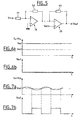
- a circuit is shown in the diagram in Figure 5.
- the amplifier includes an operational amplifier 10 mounted as an inverting amplifier with two resistors R1 and R2, the non-inverting input of the operational amplifier being connected to ground. Gv voltage gain of such amplifier is worth -R2 / R1. The output of this amplifier saturates at a determined value Vsat when the output reaches the value of the positive supply voltage of operational amplifier 10.
- the comparator comprises an operational amplifier 20 whose output can be coupled to its inverting input via a resistor R3 making it possible to introduce hysteresis, and whose non-inverting input receives a reference voltage Vref.
- the inverting input of the operational amplifier 20 is connected to the output of the operational amplifier 10, and its output delivers a signal Vout which can have a positive value or a zero value depending on the sign of the voltage Gv x Vin-Vref .
- the value of the signal Vref is lower than that of the saturation voltage Vsat of the amplifier.
- Operational amplifier 10 receives the signal as input received by the equipment, i.e. the modulated carrier, noted Wine in Figure 5. If applicable, the signal received is previously filtered using bandpass filtering and amplified with a determined (and known) gain, before being worn operational amplifier input.
- the equipment i.e. the modulated carrier, noted Wine in Figure 5.
- the signal received is previously filtered using bandpass filtering and amplified with a determined (and known) gain, before being worn operational amplifier input.
- FIG. 6a there is shown a timing diagram of the signal Gv x Vin at the output of the amplifier when the latter is saturated. This is the case when the received signal has a power level higher than the threshold S1. In this case, the signal Vout at the output of the comparator is constant and of zero value, as shown in the timing diagram of FIG. 6b.
- FIG 7a there is shown a timing diagram of the signal GvxVin at the amplifier output when it is not saturated. This is the case when the received signal has a level of power below threshold S1. In this case, the signal Vout at the output of the comparator oscillates between the zero value and the positive comparator output value, as shown in the timing diagram of Figure 7b.
- the gain Gv of the amplifier is calculated from so as to make the two cases above distinct, account given the chosen value of the threshold S1.
- the ratio between the time when the signal Vout is at the value zero and the time it is at the positive output value of the comparator varies according to the difference between the voltage Vref and the DC component of the voltage Vin. Put another way, the higher the DC component of the voltage Vin and the narrower the step width of the signal Vout, at constant period. In other words, the duty cycle of the signal Vout is lower as the component voltage Vin is high.
- the signal Vout can be operated in the sense that if it has voltage steps then it is that the power level of the signal received by the equipment is below the threshold S1 and therefore this signal must be amplified, but we also see that the duty cycle of the Vout signal gives an indication quantitative of the power level of the signal received in the since it is less than S1. This indication may advantageously be used in equipment, and this any suitable way.
- the means for measuring the power level of the received signal include digital means for measuring the duration of pulses delivered at the output of a recovery circuit rhythm.
- a circuit accepts the signal received by the equipment after demodulation and generates pulses rectangular in phase with the ripples of this signal. he it is therefore essentially a comparator circuit.
- the rising edges of these rectangular pulses are used to recover the timing of the received signal.
- Ways digital measurement of the duration of these pulses include a counter that starts on the rising edges of these pulses and that stops on their falling fronts. More the higher the final value of the counter, the higher the level of received signal strength is high. In other words, we compare this value to a determined reference value, taking into account of the chosen value of the threshold S1. If the final value of counter is less than this reference value is that the power level of the received signal is below the threshold S1 and therefore this signal must be amplified.
- the power P is less than the threshold S1. So the signal received by this equipment is amplified there, before being sent to the destination equipment CU (again via the equipment E6). The value of the power P of the signal then returns to the value U n of the nominal power at the level of the equipment E1. Before being sent in the form of an amplified signal, the message is modified at the level of the equipment E1, so as to indicate that an amplification has taken place. This can be done by incrementing the value of the word INFO by one, which then goes to 001 in binary notation.
- the same phenomenon is repeated at the level of the equipment E6, so that the message is again modified there to indicate that a new amplification takes place in this equipment.
- the value of the word INFO is for example incremented again by one unit, so that it goes to 010 in binary notation.
- the signal is emitted after amplification, that is to say with a power again equal to the nominal power U n . It is then received by the recipient equipment CU.
- the message is also modified to indicate which threshold value S1 was used by the intermediate equipment which amplifies the signal, and / or to identify said intermediate equipment. This is achieved by adding additional words in the message before it is issued by the intermediate equipment. Through example, to identify the intermediate equipment, it will added to the message a word containing the value of a number identification of this intermediate equipment.
- the invention has been described above only with reference to a nonlimiting example. It applies to networks of all type, commonplace or not, ring, star to another, as well equipment of all kinds, and means of any link (optical fibers, coaxial cables, link electromagnetic radiofrequency, microwave, or optical, etc ).
- equipment used in what precedes should be considered in its broadest sense.
- some of the network equipment can be functional equipment, i.e. having a function determined in a specific application (for example a floor lamp), while other equipment is only relays or repeaters, placed here and there in the network to breaking too far between two pieces of equipment functional.
Landscapes
- Engineering & Computer Science (AREA)
- Computer Networks & Wireless Communication (AREA)
- Signal Processing (AREA)
- Mobile Radio Communication Systems (AREA)
- Small-Scale Networks (AREA)
Abstract
Description
- d'une part les réseaux dits "banalisés" pour lesquels on connaít, lors de la réalisation et de la mise en place des équipements, la distance qui sépare deux équipements entre eux dans le réseau. Il s'agit par exemple d'un réseau de répétiteurs de ligne pour la transmission de signaux téléphoniques sur longue distance, dans lequel les répétiteurs sont distants les uns des autres d'une distance constante ou à peu près constante ;
- d'autre part les réseaux dits "non banalisés", pour lesquels la distance qui sépare deux équipements entre eux n'est pas définie à l'avance. Il s'agit par exemple d'un réseau d'équipements domestiques connectés en anneau dans une habitation, en sorte que le trajet des messages échangés, et donc a fortiori la distance parcourue par ces messages entre deux équipements, ne sont pas déterminés lors de la fabrication des équipements et/ou lors de l'installation du réseau.
- émission d'un message par l'équipement destinateur vers l'équipement destinataire, sous la forme d'un signal ayant une puissance nominale déterminée ;
- réception du signal par au moins un équipement intermédiaire du réseau, compris entre l'équipement destinateur et l'équipement destinataire ;
- mesure d'une donnée représentative de la qualité du signal reçu et comparaison de cette donnée à au moins un premier seuil ;
- lorsque la donnée mesurée est inférieure audit premier seuil, modification du message pour indiquer qu'une amplification est effectuée et amplification du signal ;
- émission du signal par l'équipement intermédiaire du réseau vers l'équipement destinataire.
- des moyens pour recevoir un signal émis par un équipement destinateur ayant une puissance nominale déterminée à l'émission ;
- des moyens pour mesurer une donnée représentative de la qualité du signal reçu ;
- des moyens pour comparer cette information à un premier seuil ;
- des moyens pour modifier un message porté par le signal de manière à indiquer qu'une amplification du signal est effectuée et des moyens pour amplifier le signal, lorsque la donnée mesurée est inférieure à ce premier seuil ;
- et des moyens pour émettre vers un équipement destinataire le message ainsi modifié sous forme d'un signal amplifié, en sorte que sa puissance est égale à la puissance nominale.
- à la figure 1, déjà analysée : le schéma d'un réseau d'équipements en anneau ;
- à la figure 2 : le format d'un message émis selon l'invention ;
- à la figure 3 : un graphique illustrant un premier mode de mise en oeuvre de l'invention ;
- à la figure 4 : un graphique illustrant un second mode de mise en oeuvre de l'invention ;
- à la figure 5 : le schéma d'un circuit compris dans un équipement selon l'invention ;
- aux figures 6a et 6b : des chronogrammes de signaux du circuit de la figure 5 dans un premier cas ;
- aux figures 7a et 7b : des chronogrammes de signaux du circuit de la figure 5 dans un second cas.
- si cette information est supérieure au seuil S1 (i.e., si P>S1), le signal est émis vers l'équipement destinataire sans être amplifié et sans que le message soit modifié ;
- si cette information est comprise entre le seuil S2 et le seuil S1 (i.e., si S2<P<S1), le signal est amplifié et émis vers l'équipement destinataire après modification du message pour indiquer qu'une telle amplification a lieu ;
- si cette information est inférieure au seuil S2 (i.e., si P<S2), alors le signal n'est pas émis.
Claims (8)
- Procédé de gestion d'un réseau d'équipements (E1-E6,CU) reliés par des moyens de liaison (LT) et dont certains au moins peuvent être destinateurs et/ou destinataires de messages, selon lequel un message émis par un équipement à destination d'un autre équipement sous la forme d'un signal ayant une puissance nominale (Un) déterminée à l'émission, est modifié pour indiquer, le cas échéant, que ledit signal a été amplifié par un équipement intermédiaire (E1,E6), compris entre l'équipement destinateur (E3) et l'équipement destinataire (CU), et par lequel ce signal transite.
- Procédé selon la revendication 1, caractérisé en ce qu'il comporte les étapes suivantes :émission d'un message (figure 2) par l'équipement destinateur (E3) vers l'équipement destinataire (CU), sous la forme d'un signal ayant une puissance nominale (Un) déterminée;réception du signal par au moins un équipement intermédiaire (E2,E1,E6) du réseau, compris entre l'équipement destinateur (E3) et l'équipement destinataire (CU);mesure d'une donnée (P) représentative de la qualité du signal reçu et comparaison de cette donnée (P) à au moins un premier seuil (S1) ;lorsque la donnée (P) mesurée est inférieure audit premier seuil (S1), modification du message (figure 2) pour indiquer qu'une amplification est effectuée, et amplification du signal ;émission du signal par l'équipement intermédiaire (E2,E1,E6) vers l'équipement destinataire (CU).
- Procédé selon la revendication 2, caractérisé en ce que l'étape de modification du message (figure 2) comprend l'incrémentation de la valeur d'un mot (INFO) dudit message.
- Procédé selon l'une des revendications 1 à 4, caractérisé en ce qu'il comporte en outre une étape de comparaison de la donnée (P) représentative de la qualité du signal à un second seuil (S2), le signal n'étant pas émis par l'équipement intermédiaire si cette information est inférieure audit second seuil (S2).
- Procédé selon l'une des revendications précédentes, caractérisé en ce que la donnée représentative du signal est le niveau de puissance du signal, ou le rapport S/N du niveau de puissance du signal sur le niveau de puissance du bruit, ou un taux d'erreur pour les données transmises.
- Procédé selon l'une quelconque des revendications précédentes, caractérisé en ce que le message est aussi modifié pour indiquer quelle valeur du premier seuil (S1) a été utilisée par l'équipement intermédiaire (E1,E6) qui amplifie le signal, et/ou pour identifier ledit équipement intermédiaire (E1,E6).
- Equipement pour la mise en oeuvre d'un procédé selon l'une des revendications précédentes , caractérisé en ce qu'il comporte :des moyens pour recevoir un signal émis par un équipement destinateur et ayant une puissance nominale (Un) à l'émission;des moyens pour mesurer une donnée (P) représentative de la qualité du signal reçu ;des moyens pour comparer cette information à un premier seuil (S1) ;des moyens pour modifier un message porté par le signal de manière à indiquer qu'une amplification du signal est effectuée et des moyens pour amplifier le signal, lorsque la donnée mesurée (P) est inférieure à ce premier seuil (S1) ;et des moyens pour émettre vers un équipement destinataire le message ainsi modifié sous forme d'un signal amplifié, en sorte que sa puissance est égale à la puissance nominale (Un).
- Message émis sous forme d'un signal par un équipement (E3) d'un réseau à destination d'un autre équipement (CU) du réseau, caractérisé en ce qu'il comporte un mot (INFO) dont la valeur indique le nombre de fois où le signal a été amplifié par un équipement intermédiaire (E1,E6) du réseau compris entre l'équipement destinateur (E3) et l'équipement destinataire (CU).
Applications Claiming Priority (2)
| Application Number | Priority Date | Filing Date | Title |
|---|---|---|---|
| FR9907110A FR2794587B1 (fr) | 1999-06-04 | 1999-06-04 | Procede de gestion d'un reseau d'equipements |
| FR9907110 | 1999-06-04 |
Publications (2)
| Publication Number | Publication Date |
|---|---|
| EP1058403A1 true EP1058403A1 (fr) | 2000-12-06 |
| EP1058403B1 EP1058403B1 (fr) | 2003-03-05 |
Family
ID=9546419
Family Applications (1)
| Application Number | Title | Priority Date | Filing Date |
|---|---|---|---|
| EP00401359A Expired - Lifetime EP1058403B1 (fr) | 1999-06-04 | 2000-05-18 | Procédé de gestion d'un reseau d'équipements |
Country Status (4)
| Country | Link |
|---|---|
| US (1) | US6356623B1 (fr) |
| EP (1) | EP1058403B1 (fr) |
| DE (1) | DE60001518T2 (fr) |
| FR (1) | FR2794587B1 (fr) |
Families Citing this family (2)
| Publication number | Priority date | Publication date | Assignee | Title |
|---|---|---|---|---|
| US6604205B1 (en) * | 2000-02-07 | 2003-08-05 | Hewlett-Packard Development Co., L.P. | System and method for state synchronization |
| AUPR850501A0 (en) * | 2001-10-29 | 2001-11-29 | Tagsys Australia Pty. Ltd. | Electronic label interrogation through incidental electromagnetic radiation |
Citations (3)
| Publication number | Priority date | Publication date | Assignee | Title |
|---|---|---|---|---|
| US4317010A (en) * | 1978-12-22 | 1982-02-23 | Fillot Jean Jacques Y | Remote monitoring system for remote locating and gain regulating of amplification circuits in data transmission line |
| US5408348A (en) * | 1993-03-16 | 1995-04-18 | Alcatel Cit | System for re-establishing the transmission quality of a link including amplifier equipments in the event of failure of one or more amplifier equipments |
| WO1997024858A2 (fr) * | 1995-12-29 | 1997-07-10 | Dsc Telecom L.P. | Systeme et procede d'amelioration des signaux vocaux |
Family Cites Families (3)
| Publication number | Priority date | Publication date | Assignee | Title |
|---|---|---|---|---|
| US6067458A (en) * | 1997-07-01 | 2000-05-23 | Qualcomm Incorporated | Method and apparatus for pre-transmission power control using lower rate for high rate communication |
| KR100228493B1 (ko) * | 1997-08-30 | 1999-11-01 | 윤종용 | 비대칭 디지털 가입자 라인 시스템에서 송출 전력제어방법 |
| US6226356B1 (en) * | 1998-06-12 | 2001-05-01 | Legerity Inc. | Method and apparatus for power regulation of digital data transmission |
-
1999
- 1999-06-04 FR FR9907110A patent/FR2794587B1/fr not_active Expired - Fee Related
-
2000
- 2000-05-18 DE DE60001518T patent/DE60001518T2/de not_active Expired - Lifetime
- 2000-05-18 EP EP00401359A patent/EP1058403B1/fr not_active Expired - Lifetime
- 2000-06-02 US US09/586,315 patent/US6356623B1/en not_active Expired - Lifetime
Patent Citations (3)
| Publication number | Priority date | Publication date | Assignee | Title |
|---|---|---|---|---|
| US4317010A (en) * | 1978-12-22 | 1982-02-23 | Fillot Jean Jacques Y | Remote monitoring system for remote locating and gain regulating of amplification circuits in data transmission line |
| US5408348A (en) * | 1993-03-16 | 1995-04-18 | Alcatel Cit | System for re-establishing the transmission quality of a link including amplifier equipments in the event of failure of one or more amplifier equipments |
| WO1997024858A2 (fr) * | 1995-12-29 | 1997-07-10 | Dsc Telecom L.P. | Systeme et procede d'amelioration des signaux vocaux |
Also Published As
| Publication number | Publication date |
|---|---|
| FR2794587B1 (fr) | 2002-09-20 |
| DE60001518D1 (de) | 2003-04-10 |
| FR2794587A1 (fr) | 2000-12-08 |
| DE60001518T2 (de) | 2003-12-24 |
| US6356623B1 (en) | 2002-03-12 |
| EP1058403B1 (fr) | 2003-03-05 |
Similar Documents
| Publication | Publication Date | Title |
|---|---|---|
| EP0912961B1 (fr) | Systeme et procede de transmission de messages, notamment pour la mise a jour de donnees enregistrees dans des etiquettes electroniques | |
| EP0053545B1 (fr) | Système de transmission d'informations à modulation directe de la lumière à liaison optique à bande passante étendue vers les fréquences basses et le continu | |
| FR2753589A1 (fr) | Relais pour systeme de radiocommunications | |
| EP0004815B1 (fr) | Système de transmission de signaux électriques à liaison optique et dispositif de contrôle automatique du gain d'une voie de réception connectée à cette liaison optique | |
| FR2623674A1 (fr) | Dispositif de transmission d'informations pour vehicule automobile et procede de mise en oeuvre d'un tel dispositif | |
| EP2756604A1 (fr) | Optimisation d'un systeme domotique utilisant un reseau local de courant porteur de ligne | |
| WO2016087725A1 (fr) | Dispositif électronique associé à un module photovoltaïque pour optimiser le débit d'une transmission bidirectionnelle de type vlc | |
| EP1058403B1 (fr) | Procédé de gestion d'un reseau d'équipements | |
| CA2093991C (fr) | Source d'impulsion optique et systeme de transmission optique a solitons comportant cette source | |
| EP3248305B1 (fr) | Commutateur éthernet pour réseau en fibre optique | |
| FR2882599A1 (fr) | Systeme de communication avec comptabilite croisee et trame de communication associee | |
| EP1160752B1 (fr) | Procédé de transmission sans fil à haute fréquence pour un dispositif de régulation de chauffage à commande à distance | |
| EP1005192A1 (fr) | Dispositif de cryptage quantique | |
| EP2805310A1 (fr) | Reveil a distance d'un equipement connecte a un reseau a liens multiples | |
| FR2928479A1 (fr) | Procede de communication entre un premier noeud et un deuxieme noeud d'une installation domotique | |
| WO2001058112A1 (fr) | Procede et dispositif pour l'attribution automatique d'adresses a une pluralite de modules interconnectes par un reseau de communication a topologie complexe | |
| FR2458961A1 (fr) | Procede de transmission de signaux binaires par un reseau etranger | |
| EP1612985B1 (fr) | Communication bidirectionelle | |
| EP3306834B1 (fr) | Véhicule ferroviaire comportant un dispositif de communication de données | |
| FR2702910A1 (fr) | Système pour rétablir la qualité de transmission d'une liaison incluant des équipements amplificateurs, en cas de défaillance d'un ou de plusieurs de ces équipements amplificateurs. | |
| EP4213413B1 (fr) | Dispositif récepteur, système, procédé de réception et méthode de communication par signal de lumière | |
| FR2727812A1 (fr) | Procede de transmission de donnees par courant porteur entre un emetteur et un ou plusieurs recepteurs d'un systeme domotique de transmission de donnees | |
| EP0253039A1 (fr) | Méthode et dispositif de protection contre les échos dans un modem | |
| EP3625930B1 (fr) | Procede et systeme de transmission serie de donnees | |
| FR2783656A1 (fr) | Dispositif et procede de communication a correction d'erreurs |
Legal Events
| Date | Code | Title | Description |
|---|---|---|---|
| PUAI | Public reference made under article 153(3) epc to a published international application that has entered the european phase |
Free format text: ORIGINAL CODE: 0009012 |
|
| AK | Designated contracting states |
Kind code of ref document: A1 Designated state(s): DE FR GB IT |
|
| AX | Request for extension of the european patent |
Free format text: AL;LT;LV;MK;RO;SI |
|
| 17P | Request for examination filed |
Effective date: 20010103 |
|
| AKX | Designation fees paid |
Free format text: DE FR GB IT |
|
| RAP1 | Party data changed (applicant data changed or rights of an application transferred) |
Owner name: STMICROELECTRONICS S.A. |
|
| 17Q | First examination report despatched |
Effective date: 20020402 |
|
| GRAH | Despatch of communication of intention to grant a patent |
Free format text: ORIGINAL CODE: EPIDOS IGRA |
|
| GRAH | Despatch of communication of intention to grant a patent |
Free format text: ORIGINAL CODE: EPIDOS IGRA |
|
| GRAA | (expected) grant |
Free format text: ORIGINAL CODE: 0009210 |
|
| AK | Designated contracting states |
Designated state(s): DE FR GB IT |
|
| REG | Reference to a national code |
Ref country code: GB Ref legal event code: FG4D Free format text: NOT ENGLISH |
|
| REF | Corresponds to: |
Ref document number: 60001518 Country of ref document: DE Date of ref document: 20030410 Kind code of ref document: P |
|
| GBT | Gb: translation of ep patent filed (gb section 77(6)(a)/1977) | ||
| PLBE | No opposition filed within time limit |
Free format text: ORIGINAL CODE: 0009261 |
|
| STAA | Information on the status of an ep patent application or granted ep patent |
Free format text: STATUS: NO OPPOSITION FILED WITHIN TIME LIMIT |
|
| 26N | No opposition filed |
Effective date: 20031208 |
|
| PG25 | Lapsed in a contracting state [announced via postgrant information from national office to epo] |
Ref country code: IT Free format text: LAPSE BECAUSE OF NON-PAYMENT OF DUE FEES Effective date: 20050518 |
|
| PGFP | Annual fee paid to national office [announced via postgrant information from national office to epo] |
Ref country code: FR Payment date: 20080530 Year of fee payment: 9 |
|
| PGFP | Annual fee paid to national office [announced via postgrant information from national office to epo] |
Ref country code: GB Payment date: 20080424 Year of fee payment: 9 |
|
| GBPC | Gb: european patent ceased through non-payment of renewal fee |
Effective date: 20090518 |
|
| REG | Reference to a national code |
Ref country code: FR Ref legal event code: ST Effective date: 20100129 |
|
| PG25 | Lapsed in a contracting state [announced via postgrant information from national office to epo] |
Ref country code: FR Free format text: LAPSE BECAUSE OF NON-PAYMENT OF DUE FEES Effective date: 20090602 |
|
| PGFP | Annual fee paid to national office [announced via postgrant information from national office to epo] |
Ref country code: IT Payment date: 20070524 Year of fee payment: 8 |
|
| PGRI | Patent reinstated in contracting state [announced from national office to epo] |
Ref country code: IT Effective date: 20091201 |
|
| PG25 | Lapsed in a contracting state [announced via postgrant information from national office to epo] |
Ref country code: GB Free format text: LAPSE BECAUSE OF NON-PAYMENT OF DUE FEES Effective date: 20090518 |
|
| PGFP | Annual fee paid to national office [announced via postgrant information from national office to epo] |
Ref country code: DE Payment date: 20100428 Year of fee payment: 11 |
|
| REG | Reference to a national code |
Ref country code: DE Ref legal event code: R119 Ref document number: 60001518 Country of ref document: DE |
|
| REG | Reference to a national code |
Ref country code: DE Ref legal event code: R119 Ref document number: 60001518 Country of ref document: DE |
|
| PG25 | Lapsed in a contracting state [announced via postgrant information from national office to epo] |
Ref country code: DE Free format text: LAPSE BECAUSE OF NON-PAYMENT OF DUE FEES Effective date: 20111130 |
|
| PGRI | Patent reinstated in contracting state [announced from national office to epo] |
Ref country code: IT Effective date: 20091201 |