EP1058401A2 - Code assignment in a CDMA wireless system - Google Patents

Code assignment in a CDMA wireless system Download PDF

Info

Publication number
EP1058401A2
EP1058401A2 EP00304341A EP00304341A EP1058401A2 EP 1058401 A2 EP1058401 A2 EP 1058401A2 EP 00304341 A EP00304341 A EP 00304341A EP 00304341 A EP00304341 A EP 00304341A EP 1058401 A2 EP1058401 A2 EP 1058401A2
Authority
EP
European Patent Office
Prior art keywords
code
codes
wireless terminals
wireless terminal
search
Prior art date
Legal status (The legal status is an assumption and is not a legal conclusion. Google has not performed a legal analysis and makes no representation as to the accuracy of the status listed.)
Granted
Application number
EP00304341A
Other languages
German (de)
French (fr)
Other versions
EP1058401B1 (en
EP1058401A3 (en
Inventor
Jiunn-Tsair Chen
Gerard Joseph Foschini
Constantinos Basil Papadias
Current Assignee (The listed assignees may be inaccurate. Google has not performed a legal analysis and makes no representation or warranty as to the accuracy of the list.)
Nokia of America Corp
Original Assignee
Lucent Technologies Inc
Priority date (The priority date is an assumption and is not a legal conclusion. Google has not performed a legal analysis and makes no representation as to the accuracy of the date listed.)
Filing date
Publication date
Application filed by Lucent Technologies Inc filed Critical Lucent Technologies Inc
Publication of EP1058401A2 publication Critical patent/EP1058401A2/en
Publication of EP1058401A3 publication Critical patent/EP1058401A3/en
Application granted granted Critical
Publication of EP1058401B1 publication Critical patent/EP1058401B1/en
Anticipated expiration legal-status Critical
Expired - Lifetime legal-status Critical Current

Links

Images

Classifications

    • HELECTRICITY
    • H04ELECTRIC COMMUNICATION TECHNIQUE
    • H04BTRANSMISSION
    • H04B7/00Radio transmission systems, i.e. using radiation field
    • H04B7/24Radio transmission systems, i.e. using radiation field for communication between two or more posts
    • H04B7/26Radio transmission systems, i.e. using radiation field for communication between two or more posts at least one of which is mobile
    • HELECTRICITY
    • H04ELECTRIC COMMUNICATION TECHNIQUE
    • H04JMULTIPLEX COMMUNICATION
    • H04J13/00Code division multiplex systems
    • H04J13/16Code allocation
    • H04J13/18Allocation of orthogonal codes
    • HELECTRICITY
    • H04ELECTRIC COMMUNICATION TECHNIQUE
    • H04BTRANSMISSION
    • H04B1/00Details of transmission systems, not covered by a single one of groups H04B3/00 - H04B13/00; Details of transmission systems not characterised by the medium used for transmission
    • H04B1/69Spread spectrum techniques
    • H04B1/707Spread spectrum techniques using direct sequence modulation
    • H04B1/7097Interference-related aspects
    • HELECTRICITY
    • H04ELECTRIC COMMUNICATION TECHNIQUE
    • H04JMULTIPLEX COMMUNICATION
    • H04J13/00Code division multiplex systems
    • H04J13/0007Code type
    • H04J13/004Orthogonal

Definitions

  • the present invention relates generally to code division multiple access (CDMA) wireless communication systems. More particularly, the present invention relates to code assignments in CDMA wireless communication systems.
  • CDMA code division multiple access
  • Wireless communication systems in which wireless terminals (e.g. fixed or mobile) communicate with fixed base stations via a wireless channel are well known in the art. Since the wireless spectrum bandwidth is limited, various techniques have been developed to allow multiple wireless terminals to share the limited bandwidth.
  • One technique is time division multiple access (TDMA) in which wireless terminals share a single frequency but are separated in the time domain with each wireless terminal being assigned a time slot.
  • Another technique is frequency division multiple access (FDMA) in which wireless terminals are separated in the frequency domain, with each wireless terminal being assigned a particular frequency.
  • TDMA time division multiple access
  • FDMA frequency division multiple access
  • the present invention is concerned with another technique for sharing limited spectrum, namely code division multiple access (CDMA).
  • CDMA code division multiple access
  • the signals of all wireless terminals share a frequency band and are sent together in time.
  • the signals of different wireless terminals are differentiated using codes.
  • Each wireless terminal is assigned a unique code ( S ) (also known as a spreading code or signature).
  • S unique code
  • the signal ( d ) transmitted from a particular wireless terminal to the base station is combined with the wireless terminal's unique code S to generate an encoded signal over a wide band of frequencies.
  • K wireless terminals (1, 2,... K )
  • the signal of the k th wireless terminal is represented as ⁇ d k ( ⁇ ) ⁇
  • the code of the k th wireless terminal is represented as S k .
  • the transmitted signal for the k th wireless terminal at the ith time instant is represented as d k ( i ) S k .
  • the combined signal for all the wireless terminals received at the base station is d 1 ( i ) S 1 + ⁇ + d K ( i ) S K .
  • the codes are ideally designed to be orthogonal such that the signal of the k th wireless terminal may be extracted at the base station by multiplying the received signal with the wireless terminal's unique code S k .
  • Signals originating at the base station are also combined with a code prior to being transmitted to each wireless terminal.
  • the wireless terminal extracts the signals from the base station by multiplying its received signal by appropriate codes.
  • CDMA technology is well known in the art of wireless communications and will not be described in further detail herein.
  • inter-user interference also known as multiple access interference (MAI)
  • MAI multiple access interference
  • This leakage is due to several factors.
  • the codes are usually not perfectly orghogonal in order to be able to accommodate a large number of terminals.
  • This non-perfect orthogonality itself also contributes to inter-user interference.
  • received signals may not all be perfectly synchronized in time, which also contributes to the inter-user interference.
  • the interference experienced by a wireless terminal in a CDMA wireless communication system is a result of a synergy between the code assigned to the wireless terminal and the particular wireless channel through which the signals of the wireless terminal pass.
  • a wireless terminal signal propagating through a particular wireless channel will experience different interference with different codes.
  • codes in a CDMA wireless communication system are assigned based on characteristics of the wireless channels.
  • codes in a CDMA wireless communication system are assigned based on characteristics of the wireless channels.
  • an iterative code optimization algorithm maintains a processing set of wireless terminals.
  • the codes for the wireless terminals within the processing set are optimized, additional wireless terminals are added to the processing set and the codes for the new processing set are optimized. This continues until the processing set consists of all the wireless terminals in the wireless system.
  • This technique called sequential packing, is advantageous because the code assignments are more likely to converge to the optimum solution when the number of wireless terminals is small and the optimal code assignment of a K -wireless terminal system is likely to be similar to that of a ( K -1) wireless terminal system.
  • the code of a target wireless terminal is assigned as follows. First, a random search of codes is performed in order to find a code which is an improvement over the currently assigned code. In one embodiment, the random search is performed by searching all available codes until an improved code is found. In an alternate embodiment, the random search is performed by searching a subset of all available codes for the best code in the subset. A performance analysis of these random search techniques is described in the detailed description. The new code found by the random search is then improved by performing a gradient search of codes. In accordance with this technique, the signal space which surrounds the new code is searched in order to further optimize the code for this wireless terminal.
  • This gradient search of codes may be performed by searching the codes which result from making a small change to the code found by the random search.
  • the new code found by the random search may also be improved by performing a gradient search of transmission delays.
  • the delay of transmission of the new code is adjusted by a small amount in order to determine the optimum delay of the code.
  • the invention provides advantages over the prior art systems. Interference is reduced at the outset by the assignment of codes based on channel characteristics, rather than randomly assigning codes at the outset and trying to remove the interference at the receiver. This substantially simplifies receiver processing.
  • Wireless terminals 110 1 , 110 2 , ... 110 K are communicating with base station 102 in accordance with the CDMA communication protocol.
  • Broken line 104 represents a logical separation between forward link (i.e., base station to wireless terminals) components above the broken line 104 and reverse link (i.e., wireless terminals to base station) components below the broken line 104.
  • Base station 102 comprises antennas 106 1 , 106 2 , ... 106 p for receiving signals from the wireless terminals 110.
  • a frequency down converter 112 receives the signals from the wireless terminals 110 and demodulates the signals to extract baseband signals.
  • the wireless channel is described by a multi-path propagation model.
  • a mathematical description of the model which provides a basis for a further description of the elements of Fig. 1 will now be given.
  • the propagation channel comprises a few dominant specular paths.
  • the baseband signal received by the base station 102 can be expressed as follows: where x ( t ) is the received baseband signal as a function of time t ; n ( t ) is the additive noise; K is the number of wireless terminals visible to the base station 102; L is the maximum number of propagation paths present in the system for each wireless terminal; a ( ⁇ k ,1 ) is the steering vector of wireless terminal k to a signal arriving from direction ⁇ k ,1 ; ⁇ k ,1 is the complex time-varying amplitude of the l th path of the k th wireless terminal, with the path amplitude being a complex Gaussian random process including both the propagation loss and the signal fading caused by the Doppler spread; is the transmitted complex baseband signal from the k th wireless terminal; ⁇ k,l is the propagation delay of the l th path of the k th wireless terminal.
  • the transmitted signal can be represented as the convolution of the data bits, the codes and the pulse-shaping function.
  • the convolution, correlation, and integration operations can be replaced by multiplication of matrices with appropriate arrangements of matrix elements from the sampled data.
  • P antennas we oversample the signals with a factor of ⁇ (i.e., we sample the signal ⁇ times in each chip).
  • i.e., we sample the signal ⁇ times in each chip.
  • the data matrix D k :( N + Q -1) ⁇ MN ⁇ is also a Toeplitz matrix with [ d k,m -1 , 0 1 ⁇ ( N ⁇ -1) , d k,m -1 , 0 1 ⁇ (( Q -1) ⁇ -1) ] T as its first column, and [ d ki , 0 1 ⁇ ( N ⁇ -1) , d k,m +1 , 0 1 ⁇ ( N ⁇ -1) ,..., d k,m + M -1 , 0 1 ⁇ ( N ⁇ -1) ] as its first row, where ⁇ d k,m ⁇ are the binary phase shift keying (BPSK) data bits of the k th wireless terminal.
  • BPSK binary phase shift keying
  • the l th row of denotes the temporal signature of the lth path of the k th wireless terminal seen at the receiver.
  • the l th column of A k denotes the spatial signature of the l th path of the k th wireless terminal. If we consider the impulse response of the wireless channel, and assume there is only one symbol transmitted for each wireless terminal, then D k equals d k ,1 times an identity matrix.
  • equation (2) can be written as where the "vec" operator stacks columns of a matrix putting them one below another, ⁇ denotes the Kronecker product, ⁇ denotes the Khatri-Rao product (column-wise Kronecker product), and is the l th row of .
  • ⁇ a ( ⁇ k , l ) is the space-time signature of the l th path of the k th wireless terminal. If there is more than one symbol transmitted for each wireless terminal, intersymbol interference results in space-time signatures overlapped in time within the received signal X .
  • the joint channel estimator 114 receives the baseband signal and, using the above described model, determines characteristics of the channels of the wireless terminals 110.
  • Channel information including the path DOAs (direction of arrival) ⁇ k,l ⁇ , the propagation delays ⁇ k,l ⁇ , and the complex path fading amplitudes ⁇ k,l ⁇ are required in the space time matched filter 116, the signal detector 120, and the code optimizer 118.
  • the joint channel estimator 114 determines these channel characteristics as follows.
  • the joint channel estimator 114 estimates the path DOAs ( ⁇ k,l ) and the propagation delays ( ⁇ K ,1 ) by using known subspace-based algorithms.
  • Appropriate subspace-based algorithms which may be used by the joint channel estimator 114 are described in, M. C. Vanderveen, C. B. Papadias, and A. Paulraj, Joint Angle and Delay Estimation (JADE) for Multi-Path Signals Arriving at an Antenna Array, IEEE Communications Letters, vol. 1, no. 1, pp. 12-14, Jan. 1997. Since both the path DOAs and the propagation delays usually remain unchanged over a long period of time, the above referenced subspace-based algorithms may be used in order to obtain accurate channel estimations.
  • ⁇ A k ⁇ can be reconstructed by using the array manifold a (.) and ⁇ G k ⁇ can be reconstructed by using the temporal manifold g(.).
  • ⁇ S k ⁇ denotes the wireless terminal codes, which are known to the base station 102.
  • the only remaining unknowns left in equation (2) are ⁇ B k ⁇ and ⁇ D k ⁇ , which are the complex path fading amplitudes and the transmitted data symbol matrix respectively.
  • the data symbol matrix can be obtained by using known training sequences or in a decision-directed fashion, i.e., the demodulated data symbols can be easily used as training data.
  • the channel estimates calculated by the joint channel estimator 114 are provided to space-time matched filter 116, code optimizer 118, and signal detector 120.
  • the space-time matched filter 116 is used to obtain sufficient statistics for demodulating the digitally modulated signals.
  • the output of the space-time matched filter 116 may be written as Where "tr" denotes the trace of a matrix, and X m : P ⁇ ( N + Q - 1) ⁇ is copied from the (( m -1) n ⁇ +1) th to ( mN ⁇ + Q ⁇ ) th columns of X .
  • Equation (8) can be rewritten as where N m and D m / i are the sub-matrices of N and D i respectively, so X m is constructed from X .
  • D m / i is a Toeplitz square matrix with as its first column, and as its first row. Therefore, the first term on the right hand side of equation (9) can be written as where ⁇ denotes the Hadamard product or the entry-wise product, (+1) and (-1) are both sub-matrices of .
  • the output of the space-time matched filter 116 is provided to the signal detector 120.
  • the signal detector 120 also receives the channel estimations from the joint channel estimator 114 and the codes which are output from the code optimizer 118.
  • K 0 in-cell wireless terminals need to be demodulated at the base station 102. Therefore, only the space time matched filter 116 outputs related to these K 0 wireless terminals are processed in the signal detector 120.
  • This embodiment generally performs better than the zero-forcing solution of the decorrelator in the second embodiment, when taking into account the effect of the correlated noise.
  • the coloring matrix of the noise, N in equation (11), at the output of the space time matched filter 116 is given by:
  • the reverse link data outputs of the signal detector 120 may be provided to, for example, a telephone network node such as a switch.
  • step 206 of Fig. 2 in which the code optimizer 118 performs a random code search.
  • the less dense regions of the signal space must be explored in order to maximize the distances between the wireless terminal codes. More particularly, we need to adopt some of the un-used codes by random search in order to span the entire signal space. It is also noted that a good code for one wireless terminal may not necessarily be a good code for another wireless terminal because the wireless channel of each wireless terminal is different. Therefore, a random-searching procedure of codes is required for each wireless terminal in order to cover those less dense areas in the signal space. When the number of wireless terminals is small compared to the dimension of the signal space, it is easier to find a less dense area by random searching. Otherwise, longer searching may be required.
  • the first technique is to continue searching all the possible codes until a better code is obtained. If the number of wireless terminals is large compared to the dimension of the signal space, it may take a long time to find a better code.
  • the second technique is to only search a subset of randomly-picked codes, and choose the best code in the subset if it is better than the original code prior to the random search. If the number of wireless terminals is small compared to the dimension of the signal space, the second approach might require a large amount of unnecessary searching. However, if the number of wireless terminals is large compared to the dimension of the signal space, this second technique might stop at a sub-optimal value.
  • One skilled in the art would recognize that other techniques could be used to implement the random code search.
  • the code for the target wireless terminal may be further optimized by gradient-searching this less dense area in the signal space.
  • a gradient search of codes is performed as follows. A small change is made to the code of the target wireless terminal to determine if there is improvement in terms of the minimum SINR. Assume the length of the code is N chips long. N different codes are generated by individually changing the sign of each chip in the code. These N different codes are then compared with the original code. If none of the new N codes performs better than the original code, then the gradient search of codes is considered to be converged. Otherwise, the original code is replaced with the best code among the N new codes, and the same process is repeated. Note that the change of the sign of only one chip in the code results in only a minimum change of the code on the transmission side. It is expected that such a minimum change in direction will also result in only a minor change of the code as seen at the receiver.
  • step 220 a gradient search of transmission delays is performed as follows.
  • the delay of transmission of the wireless terminal code is adjusted by a small step ⁇ T in order to determine the optimum delay of a specific code.
  • the step size ⁇ T should be in inverse proportion to the signal bandwidth.
  • step 222 the gradient search of codes (step 210) and the gradient search of delays (step 220) continues until no further improvement in the SINR for the target wireless terminal is achieved. It is determined in step 224 whether the code searching steps (steps 204-222) have converged. Convergence of the code search is defined as the condition where there is no space for further improvement regardless of which target wireless terminal of the processing subset is picked. Convergence may be determined by repeating steps 204 through 208 until there is no improvement. Eventual convergence is guaranteed because there are only a finite number of possible code assignments, although this finite number 2 KN G K could be very large, where G is defined as the number of possible transmission delays.
  • step 224 if the test in step 224 is no, then control returns to step 204 and a new wireless terminal from the processing set is chosen as the target wireless terminal and the code search of steps 206-222 are repeated. Note that the new target may be a wireless terminal already chosen during this processing loop. If the test in step 224 is yes, then in step 226 it is determined whether the number of wireless terminals in the processing set equals the total number of wireless terminals communicating with base station 102. If not, then in step 228 another wireless terminal is added to the processing set and steps 204 through 224 are repeated for the new processing set.
  • the optimized codes from code optimizer 118 are provided to the signal detector 120 and to the forward link modulator 122.
  • the forward link modulator 122 also receives forward link data inputs which may be, for example, telephone signals from a telephone network.
  • the forward link modulator 122 modulates the forward link data and the codes received from the code optimizer 118 and provides the modulated signal to the frequency up-converter 124.
  • the frequency up-converter 124 transmits the signal to the wireless terminals 110 via antenna 126.
  • the newly assigned codes are transmitted to the wireless terminals 110.
  • the wireless terminals then use the newly assigned codes for subsequent reverse link communication.
  • the signal detector 120 also receives the new codes from the code optimizer 118 so that the signal detector 120 can decode the subsequent reverse link communication.
  • the use of a processing set results in an iterative algorithm in which wireless terminals are added into the processing subset one by one and only after the code optimization procedure has converged for the prior processing set.
  • This technique which we call sequential packing, is advantageous because the code assignments are more likely to converge to the optimum solution when the number of wireless terminals is small.
  • the optimal code assignment of a K -wireless terminal system is likely to be similar to that of a ( K -1) wireless terminal system.
  • the following portion of the description addresses performance issues of the above described code assignment techniques.
  • the performance of the algorithm described in conjunction with Fig. 2 depends on the number of wireless terminals, the dimension of the signal space, the overall channel of each wireless terminal, and the adaptation procedure used for code optimization.
  • G 1, a code of 4 chips long, up to 4 wireless terminals, a single antenna
  • E b / N 0 ⁇ .
  • Each curve in Fig. 3 is labeled by the number of wireless terminals in the system.
  • Fig. 3 the horizontal axis of Fig. 3 represents the percentage of the bottom performance among all the possible code assignments.
  • the minimum SINR is very low most of the time without code assignment optimization regardless of the number of wireless terminals in the system.
  • the improvement on the minimum SINR caused by reassigning the wireless terminal codes is very significant when the number of wireless terminals is close to the dimension of the signal space. When the number of wireless terminals is small, the improvement is still great but not as significant, because it is relatively easy to separate the code vectors in the signal space.
  • the top 2 percent performance of Fig. 3 is expanded. In this example, we can obtain orthogonal codes if the algorithm of Fig. 2 converges to the minimum SINR among the top 20 percent, top 1.5 percent and top 0.05 percent, respectively, when there are 2, 3 and 4 wireless terminals in the system.
  • p i (x) be the probability density function of x after the i th search cycle.
  • the probability density function after the first cycle of searching becomes where " In " denotes the natural log.
  • the cumulative distribution function (CDF) of the minimum SINR after the i th cycle of searching can then be written as
  • the average number of blind searches in the i th search cycle can be written as
  • Fig. 5 shows the improvement of the probability density function of the minimum SINR using the random search technique of searching all possible codes until a code which is better than the current code is found. Each curve in the figure is labeled by the number of the search cycles. By comparing Fig. 3 with Fig. 5, the number of cycles of blind searches which are required to achieve a certain minimum SINR performance can be determined.
  • Fig. 6 shows the number of blind search cycles required to reach certain performance levels for the two random search techniques. Section 602 of Fig. 6 shows the number of search cycles required to have 50, 90, and 99 percent chance for the search results to be among the top 10, 1 and 0.1 percent of performance of all possible code assignments for the first random search technique which searches until a better code is found. For example, to have a 90 percent chance to reach the top 1 percent of performance using the first random search technique, we need to search for a better assignment at least 7 times.
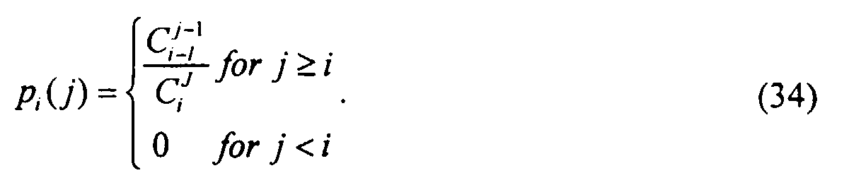
  • the second search strategy is to randomly search through a fixed number of code assignments to find the code with the best minimum SINK. If we search through i possible code assignments, the probability of picking the j th assignment p i ( j ) is given by However, if we use i - 1 pairwise comparisons to search through i possible code assignments and we allow the same code assignments to repeat within i assignments, we can modify p i ( j ) as follows: In each pairwise comparison, if the j th / 1 assignment is first used, there is a j 1 -1 / J -1 chance that the j th / 1 assignment will be compared to an assignment with poorer minimum SINR, while there is a 1 / J -1 chance that the j th / 1 assignment will be compared to an assignment with better minimum SINR.
  • Fig. 7 shows the improvement of the probability density function of the minimum SINR using the second search strategy of searching through a fixed number of code assignments. Each curve in the figure is labeled by the number of assignments searched. Comparing Fig. 3 with Fig. 7, we can determine how many code assignments must be searched in order to achieve a certain minimum SINR performance. Section 604 of Fig. 6 shows the number of searches required to have 50, 90, and 99 percent chance for the search results to rank among top 10, 1 and 0.1 percent of performance of all possible code assignments using the second random search strategy.
  • the convergence criterion, the step-size of the gradient search, and the technique of picking a target wireless terminal can be controlled in order to adjust the algorithm complexity and convergence speed. If the complexity of the assignment searching procedure is increased, then the minimum SINR performance is expected to improve, while it might take more time for the algorithm to converge. This trade-off is investigated in order to determine how much increase in algorithm complexity is required to achieve a certain performance improvement. The number of equivalent blind searches n and in the proposed algorithm is estimated. Based on n and , and Figs. 5-7, the improvement on the minimum SINR among all the possible code assignments is evaluated.
  • the random searches and the gradient searches serve the respective purposes of region dividing and local regional searching in the signal space.
  • the random search first looks for the regions where a higher minimum SINR is more likely to occur. This random search may be seen as dividing the signal space into small regions and then finding one of the best regions among other sub-optimal regions.
  • the gradient search then searches for the best minimum SINR around the best local region determined by the random search.
  • Equation (41) represents the number of searches in each step of the gradient search; N searches for the code, and 2 searches for the transmission delay.

Landscapes

  • Engineering & Computer Science (AREA)
  • Computer Networks & Wireless Communication (AREA)
  • Signal Processing (AREA)
  • Mobile Radio Communication Systems (AREA)

Abstract

A CDMA wireless communication system for communicating with wireless terminals (110) comprises a channel estimator (114) for determining characteristics of the wireless channels of the wireless terminals. The channel characteristics are used by a code optimizer (118) to assign spreading codes to the wireless terminals. In one embodiment, the code optimizer utilizes an iterative code optimization algorithm and maintains a processing set of wireless terminals. The code optimizer (118) chooses target wireless terminals and performs a random code search in order to find an improved code for the target wireless terminal. The improved code found in the random code search is further improved by performing a gradient search of codes in the signal space in the vicinity of the improved code and by performing a gradient search of transmission delays. The improved codes are transmitted to the wireless terminals (110) for use in reverse link communication.

Description

Field of the Invention
The present invention relates generally to code division multiple access (CDMA) wireless communication systems. More particularly, the present invention relates to code assignments in CDMA wireless communication systems.
Background of the Invention
Wireless communication systems in which wireless terminals (e.g. fixed or mobile) communicate with fixed base stations via a wireless channel are well known in the art. Since the wireless spectrum bandwidth is limited, various techniques have been developed to allow multiple wireless terminals to share the limited bandwidth. One technique is time division multiple access (TDMA) in which wireless terminals share a single frequency but are separated in the time domain with each wireless terminal being assigned a time slot. Another technique is frequency division multiple access (FDMA) in which wireless terminals are separated in the frequency domain, with each wireless terminal being assigned a particular frequency.
The present invention is concerned with another technique for sharing limited spectrum, namely code division multiple access (CDMA). In a CDMA system, the signals of all wireless terminals share a frequency band and are sent together in time. The signals of different wireless terminals are differentiated using codes. Each wireless terminal is assigned a unique code (S) (also known as a spreading code or signature). The signal (d) transmitted from a particular wireless terminal to the base station is combined with the wireless terminal's unique code S to generate an encoded signal over a wide band of frequencies. If there are K wireless terminals (1, 2,... K), the signal of the k th wireless terminal is represented as {dk (·)} and the code of the k th wireless terminal is represented as S k . The transmitted signal for the k th wireless terminal at the ith time instant is represented as dk (i)Sk . Thus, the combined signal for all the wireless terminals received at the base station is d 1(i)S 1+···+dK (i)SK . The codes are ideally designed to be orthogonal such that the signal of the kth wireless terminal may be extracted at the base station by multiplying the received signal with the wireless terminal's unique code Sk . Signals originating at the base station are also combined with a code prior to being transmitted to each wireless terminal. Upon receipt of the signals, the wireless terminal extracts the signals from the base station by multiplying its received signal by appropriate codes. CDMA technology is well known in the art of wireless communications and will not be described in further detail herein.
One problem with CDMA systems is inter-user interference (also known as multiple access interference (MAI)) which results from the leakage of signals of one wireless terminal into the signal of another wireless terminal. This leakage is due to several factors. First, there is multipath propagation which results in the same signal being propagated along multiple paths with different time delays. Moreover, the codes are usually not perfectly orghogonal in order to be able to accommodate a large number of terminals. This non-perfect orthogonality itself also contributes to inter-user interference. Also, received signals may not all be perfectly synchronized in time, which also contributes to the inter-user interference.
In order to deal with the interference problem, current systems generally perform complex operations at the receiver in an attempt to remove this unwanted interference. One approach of dealing with interference is single user processing, in which a receiver uses only knowledge of a single signal (e.g. the signal associated with a single wireless terminal) to process the incoming signal. A more sophisticated approach is multi-user processing, wherein the receiver uses knowledge of all signals in order to demodulate them all in a joint fashion. This multi-user appraoch is generally only performed at base stations because of the significant processing overhead which it requires.
Summary of the Invention
We have realized that the interference experienced by a wireless terminal in a CDMA wireless communication system is a result of a synergy between the code assigned to the wireless terminal and the particular wireless channel through which the signals of the wireless terminal pass. Thus, a wireless terminal signal propagating through a particular wireless channel will experience different interference with different codes.
In accordance with the invention, codes in a CDMA wireless communication system are assigned based on characteristics of the wireless channels. By coordinating the assignment of codes among the wireless terminals based on the wireless channels, the total interference among the wireless terminals is reduced and performance of the overall wireless communication system is improved.
In accordance with one embodiment of the invention, an iterative code optimization algorithm maintains a processing set of wireless terminals. In accordance with the algorithm, when the codes for the wireless terminals within the processing set are optimized, additional wireless terminals are added to the processing set and the codes for the new processing set are optimized. This continues until the processing set consists of all the wireless terminals in the wireless system. This technique, called sequential packing, is advantageous because the code assignments are more likely to converge to the optimum solution when the number of wireless terminals is small and the optimal code assignment of a K-wireless terminal system is likely to be similar to that of a (K-1) wireless terminal system.
In accordance with another embodiment of the invention, during the processing of each processing set a technique called target wireless terminal isolation is used. Instead of updating all the codes for all the wireless terminals in the processing set, a target wireless terminal is chosen and its code is optimized prior to moving on to optimize the codes of the other wireless terminals in the processing set. This technique also speeds up convergence because before the convergence of the code optimization, most of the codes may have already achieved good orthogonal distribution. Disturbing all the codes would likely slow down the convergence speed.
In accordance with one embodiment of the optimization algorithm, the code of a target wireless terminal is assigned as follows. First, a random search of codes is performed in order to find a code which is an improvement over the currently assigned code. In one embodiment, the random search is performed by searching all available codes until an improved code is found. In an alternate embodiment, the random search is performed by searching a subset of all available codes for the best code in the subset. A performance analysis of these random search techniques is described in the detailed description. The new code found by the random search is then improved by performing a gradient search of codes. In accordance with this technique, the signal space which surrounds the new code is searched in order to further optimize the code for this wireless terminal. This gradient search of codes may be performed by searching the codes which result from making a small change to the code found by the random search. The new code found by the random search may also be improved by performing a gradient search of transmission delays. In accordance with this technique, the delay of transmission of the new code is adjusted by a small amount in order to determine the optimum delay of the code.
The invention provides advantages over the prior art systems. Interference is reduced at the outset by the assignment of codes based on channel characteristics, rather than randomly assigning codes at the outset and trying to remove the interference at the receiver. This substantially simplifies receiver processing.
These and other advantages of the invention will be apparent to those of ordinary skill in the art by reference to the following detailed description and the accompanying drawings.
Brief Description of the Drawings
  • Fig. 1 shows a system in accordance with one embodiment of the invention;
  • Fig. 2 is a flowchart of the steps performed to assign codes to wireless terminals in accordance with one embodiment of the invention;
  • Fig. 3 is a graph showing the minimum SINR distribution in an example system;
  • Fig. 4 is a graph showing the top 2 percent performance of Fig. 3;
  • Fig. 5 is a graph showing the improvement of the probability density function of the minimum SINR using a first search strategy;
  • Fig. 6 is a graph showing the number of search cycles required to reach certain performance levels; and
  • Fig. 7 is a graph showing the improvement of the probability density function of the minimum SINR using a second search strategy.
  • Detailed Description
    A system in accordance with one embodiment of the present invention is shown in Fig. 1. Wireless terminals 1101, 1102, ... 110 K are communicating with base station 102 in accordance with the CDMA communication protocol. Broken line 104 represents a logical separation between forward link (i.e., base station to wireless terminals) components above the broken line 104 and reverse link (i.e., wireless terminals to base station) components below the broken line 104. Base station 102 comprises antennas 1061, 1062, ... 106p for receiving signals from the wireless terminals 110. A frequency down converter 112 receives the signals from the wireless terminals 110 and demodulates the signals to extract baseband signals. Thus, the output of frequency downconverter 112 is the combined baseband signal from all wireless terminals κ p 1 d 1(i)S 1+···+κ pKdK (i)SK , where κ pk is the combined effect of the wireless channel of the kth terminal and the pth antenna element. Note that the signal model used herein does not assume intersymbol interference (ISI), but one skilled in the art could readily extend the model to include ISI. The combined signal is provided to a joint channel estimator 114 and a space-time matched filter 116. The joint channel estimator 114 receives the baseband signal and determines the characteristics of the wireless channels κ pk over which the signals have been received.
    The wireless channel is described by a multi-path propagation model. A mathematical description of the model which provides a basis for a further description of the elements of Fig. 1 will now be given. In large cells with high base station antenna platforms, the propagation channel comprises a few dominant specular paths. In such a case, the baseband signal received by the base station 102 can be expressed as follows:
    Figure 00060001
    where x(t) is the received baseband signal as a function of time t; n(t) is the additive noise; K is the number of wireless terminals visible to the base station 102; L is the maximum number of propagation paths present in the system for each wireless terminal; a( k ,1) is the steering vector of wireless terminal k to a signal arriving from direction  k ,1 ; β k ,1 is the complex time-varying amplitude of the lth path of the kth wireless terminal, with the path amplitude being a complex Gaussian random process including both the propagation loss and the signal fading caused by the Doppler spread;
    Figure 00060002
    is the transmitted complex baseband signal from the kth wireless terminal; τ k,l is the propagation delay of the lth path of the kth wireless terminal.
    In a CDMA system with the length of the spreading code N equal to the number of chips in a symbol period, the transmitted signal
    Figure 00060003
    can be represented as the convolution of the data bits, the codes and the pulse-shaping function. Assuming band-limited signals in the system, if each continuous signal is sampled at a rate which is higher than twice the Nyquist rate, then the convolution, correlation, and integration operations can be replaced by multiplication of matrices with appropriate arrangements of matrix elements from the sampled data. In the present embodiment, we assume P antennas, and we oversample the signals with a factor of ρ (i.e., we sample the signal ρ times in each chip). In addition, there are N chips in each data symbol, and M data symbols are considered. We also assume that the maximum path delay plus the length of the pulse-shaping function is no greater than QT c and that Q < N, where Tc is the chip period (if Q is much smaller than N, then the system is quasi-synchronous). After sampling, we can express the received signal X as
    Figure 00070001
    where X: P × MNρ and N: P × MNρ are, respectively, the received signal and the additive Gaussian noise; A k : P × L is given by A k =[a( k ,1)a( k ,2)...a( k , L )]; B k : L × L is given by B k = diag{β k } with β k = [β k ,1, β k ,2,...,β k,L ] T ; and the i,jth element of G k : L × Qρ can be written as g(t 0 + j-1 / ρ Tc - τ k,i ) with g(.) being the normalized pulse-shaping function. The code matrix S k : Qp × (N + Q-1)ρ is a Toeplitz matrix with [sk ,1,0 1×( Q ρ-1)] T as its first column, and [sk ,1 0 1×(ρ-1),sk ,2,0 1×(ρ-1),...,Sk,N ,0 1×( Q ρ-1)] as its first row, where sk ,1,sk ,2,...,sk,N is the normalized code of the kth wireless terminal. The data matrix D k :(N+Q-1)ρ×MNρ is also a Toeplitz matrix with [dk,m -1,0 1×( N ρ-1),dk,m -1,0 1×(( Q -1)ρ-1)] T as its first column, and [dki ,0 1×( N ρ-1),dk,m +1,0 1×( N ρ-1),...,dk,m + M -1,0 1×( N ρ-1)] as its first row, where {dk,m } are the binary phase shift keying (BPSK) data bits of the kth wireless terminal.
    In addition, the temporal signature matrix
    Figure 00070002
    : L × (N + Q - 1)ρ is defined as = G k S k . The lth row of denotes the temporal signature of the lth path of the kth wireless terminal seen at the receiver. Similarly, the lth column of A k denotes the spatial signature of the lth path of the kth wireless terminal. If we consider the impulse response of the wireless channel, and assume there is only one symbol transmitted for each wireless terminal, then Dk equals dk ,1 times an identity matrix. After stacking the columns of X, equation (2) can be written as
    Figure 00070003
    where the "vec" operator stacks columns of a matrix putting them one below another, ⊗ denotes the Kronecker product, ∘ denotes the Khatri-Rao product (column-wise Kronecker product), and
    Figure 00080001
    is the lth row of . Thus,
    Figure 00080002
    a( k , l ) is the space-time signature of the lth path of the kth wireless terminal. If there is more than one symbol transmitted for each wireless terminal, intersymbol interference results in space-time signatures overlapped in time within the received signal X.
    Returning now to Fig. 1, the joint channel estimator 114 receives the baseband signal and, using the above described model, determines characteristics of the channels of the wireless terminals 110. Channel information including the path DOAs (direction of arrival) { k,l }, the propagation delays {τ k,l }, and the complex path fading amplitudes {β k,l } are required in the space time matched filter 116, the signal detector 120, and the code optimizer 118. The joint channel estimator 114 determines these channel characteristics as follows.
    The joint channel estimator 114 estimates the path DOAs ( k,l ) and the propagation delays (τ K ,1) by using known subspace-based algorithms. Appropriate subspace-based algorithms which may be used by the joint channel estimator 114 are described in, M. C. Vanderveen, C. B. Papadias, and A. Paulraj, Joint Angle and Delay Estimation (JADE) for Multi-Path Signals Arriving at an Antenna Array, IEEE Communications Letters, vol. 1, no. 1, pp. 12-14, Jan. 1997. Since both the path DOAs and the propagation delays usually remain unchanged over a long period of time, the above referenced subspace-based algorithms may be used in order to obtain accurate channel estimations. For purposes of this description, it is assumed that we have perfect information on the path DOAs and the propagation delays as a result of one of the above referenced algorithms. With the path DOAs and propagation delays available, {A k } can be reconstructed by using the array manifold a(.) and {G k } can be reconstructed by using the temporal manifold g(.). Note that {S k } denotes the wireless terminal codes, which are known to the base station 102. The only remaining unknowns left in equation (2) are {B k } and {D k }, which are the complex path fading amplitudes and the transmitted data symbol matrix respectively. The data symbol matrix can be obtained by using known training sequences or in a decision-directed fashion, i.e., the demodulated data symbols can be easily used as training data. To estimate {B k }, we can re-write equation (2) as
    Figure 00090001
    where A = [A 1, A 2, ..., A K ]; B = diag(B 1,B 2, ..., B K ); G = diag(G 1, G 2, ..., G K ); S = diag(S 1, S 2, ..., S K ); and D = [D T / 1 1, D T / 2, ..., D T / K] T . The least square criterion is used to estimate the fading amplitudes hat β as β = ((GSD) T o A) +vec(X) where β and = [β and T / 1β and T / 2,...,β and T / K] T with β and k being the least square estimate of β k ; and (.) + denotes the pseudo-inverse.
    The channel estimates calculated by the joint channel estimator 114 are provided to space-time matched filter 116, code optimizer 118, and signal detector 120.
    The space-time matched filter 116 is used to obtain sufficient statistics for demodulating the digitally modulated signals. The output of the space-time matched filter 116 may be written as
    Figure 00090002
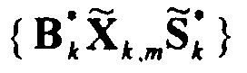
    Where "tr" denotes the trace of a matrix, and X m : P × (N + Q - 1)ρ is copied from the ((m-1)nρ+1) th to (mNρ+Qρ) th columns of X. The matrix multiplication of A * / k and X m denotes the path-wise beam-forming. Let X k,m = A * / k X m . The trace of the matrix multiplication tr
    Figure 00090003
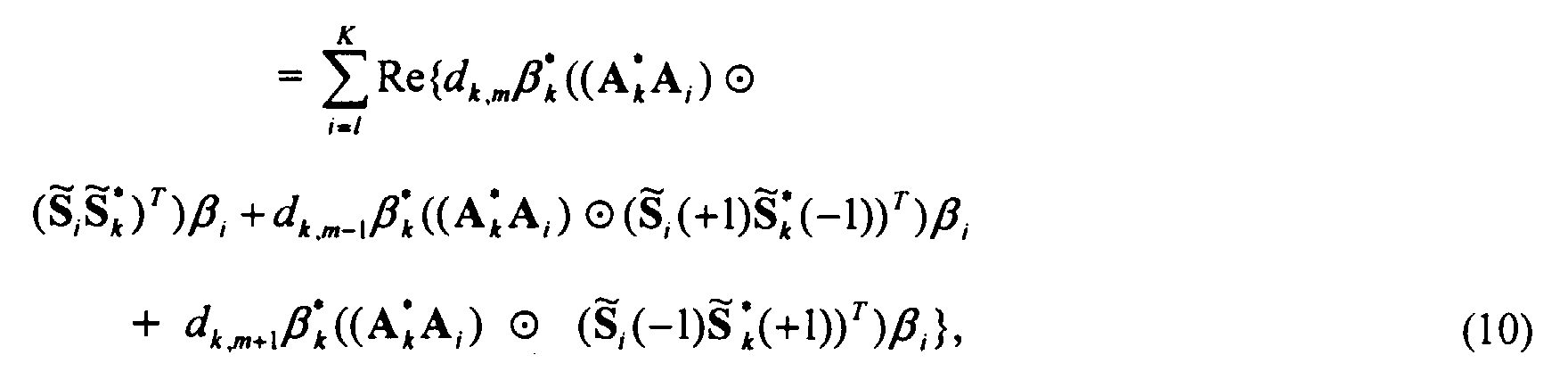
    denotes the matched filter for the temporal signature and the maximum-ratio path combining of the kth wireless terminal. To expand X k,m , equation (8) can be rewritten as
    Figure 00100001
    where N m and D m / i are the sub-matrices of N and D i respectively, so X m is constructed from X. Note that D m / i is a Toeplitz square matrix with
    Figure 00100002
    as its first column, and
    Figure 00100003
    as its first row. Therefore, the first term on the right hand side of equation (9) can be written as
    Figure 00100004
    where ⊙ denotes the Hadamard product or the entry-wise product, (+1) and (-1) are both sub-matrices of . The rightmost and the left most (Q-1)ρ columns are respectively denoted by (+1) and (-1). For additional information on the Hadamard product/entry-wise product, see Roger A. Hurn and Charles R. Johnson, Topics in Matrix Analysis, Cambridge University, Press 1991.
    We can stack the matrices and write the received signal at the output of the space-time matched filter 116 as
    Figure 00100005
    where X = [ X 1,1, X 2,1,..., X K ,1, X 1,2,..., X K,M ] T , d = [d 1,1 d 2,1,...,dK ,1,d 1,2,...dK,M ] T , and N = [ N 1,1, N 2,1,..., N K ,1, N 1,2,..., N K,M ] T with N k,m = Re{tr{B * / k A * / k N m
    Figure 00100006
    }}. If we define H(0):
    K x K, H(+1): K x K, and H(-1): K x K as

    Figure 00100007
    Figure 00110001
    Figure 00110002
    with
    A = [A 1, A 2,...,A K ],
    Figure 00110003
    =[
    Figure 00110004
    ,
    Figure 00110005
    ,...,
    Figure 00110006
    ] T ,
    Figure 00110007
    (+1) = [
    Figure 00110008
    (+1),
    Figure 00110009
    (+1),...,
    Figure 00110010
    (+1)] T ,
    (-1)=[ (-1), (-1),..., )(-1)] T
    and define the fading amplitude matrix B: K L x K as B = diag ((β12,...,β K ), then
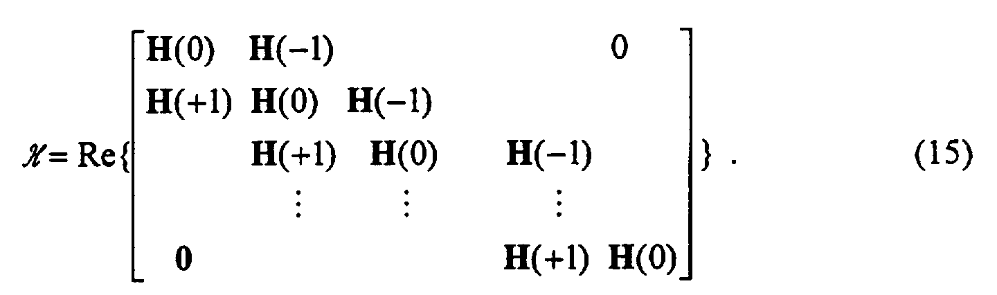
    Figure 00110011
    can be expressed as
    Figure 00110012
    The output of the space-time matched filter 116 is provided to the signal detector 120. The signal detector 120 also receives the channel estimations from the joint channel estimator 114 and the codes which are output from the code optimizer 118. We assume that only K 0 in-cell wireless terminals need to be demodulated at the base station 102. Therefore, only the space time matched filter 116 outputs related to these K 0 wireless terminals are processed in the signal detector 120. We now describe three possible embodiments of the signal detector 120.
    First, signal detector 120 may be implemented as a single wireless terminal detector. In this embodiment K 0 slicers are used at each output of the space-time matched filter 116. Decisions are instantaneous with no delay. The data estimate is given by d k,m = sgn(X k,m ),    where X k,m is the output of the space time matched filter 116 in equation (8). In a second embodiment, signal detector 120 may be implemented as a decorrelator. In this embodiment, a zero-forcing solution is applied to solve equation (11). The data estimate can then be written as
    Figure 00120001
    In a third embodiment, signal detector 120 may be implemented as a minimum mean square error (MMSE) detector. This embodiment generally performs better than the zero-forcing solution of the decorrelator in the second embodiment, when taking into account the effect of the correlated noise. The coloring matrix of the noise, N in equation (11), at the output of the space time matched filter 116 is given by:
    Figure 00120002
    The data estimate for the MMSE detector can then be expressed as
    Figure 00120003
    where σ 2 / n denotes the noise variance chosen to match the desired E b / N 0 with Eb being the bit energy and N 0 being the average noise variance, and σ 2 / b = 1 for the BPSK modulation scheme. It is noted that in both the decorrelator and the MMSE detector embodiments, the maximum possible delay could be up to M symbols because of the block processing of the asynchronous signals. The reverse link data outputs of the signal detector 120 may be provided to, for example, a telephone network node such as a switch.
    In accordance with the invention, the base station 102 includes a code optimizer 118 for assigning codes to wireless terminals. The steps performed by the code optimizer 118 will be described in conjunction with the flowchart of Fig. 2. In one embodiment, the code optimizer 118 is implemented using a computer processor executing stored computer program code. Thus, the code optimizer operates under control of the processor executing stored computer program code. The computer program code defines the steps described herein in conjunction with the flowchart of Fig. 2. Given the description contained herein, one skilled in the art could readily implement the code optimizer 118 in other ways. For example, the code optimizer 118 could also be implemented using hardware, or some combination of hardware and software.
    The steps shown in the flowchart of Fig. 2 are performed by the code optimizer 118 in order to optimize the codes assigned to the wireless terminals communicating with the base station 102. In step 202, as processing set is initialized with one of the wireless terminals. In step 204 a target wireless terminal is chosen from the processing set. If step 204 is executed immediately following step 202, then there will only be one wireless terminal in the processing set and that wireless terminal will be chosen as the target wireless terminal. In step 206 a random code search is performed for the wireless terminal chosen as the target in step 204. The random code search is performed in order to try to improve the current code assigned to the target wireless terminal by attempting to reduce the interference experienced by the target wireless terminal.
    One way to suppress the mutual interference among the wireless terminals is to maximize the minimum signal to interference-plus-noise ratio (SINR) ξmin among in-cell wireless terminals, where
    Figure 00130001
    The SINR of the kth wireless terminal ξ k can be written as the power ratio of the signal and the interference-plus-noise: ξ k = ξ S,k ξ l,k + ξ N,k The signal power ξ S : K × 1 can be written as ξ S = diag(H(0)) ⊙ conj(diag(H(0)), where H(0) is given in equation (12), "conj" is the complex conjugate operation, and the output of diag(.) is a column vector consisting of the diagonal elements of the argument matrix. The interference power ξ I : K × 1 can be written as ξ I = diag(HH*)-ξ S , where H = [H(-1),H(0),H(+1)], and H(0), H(+1), and H(-1) are given in equations (12), (13) and (14) respectively. The noise power ξ N : Kx1 can be written as ξ N = σ2 n 2 diag(H(0)). Note that in using the minimum SINR as the criteria for code optimization, two factors are taken into consideration: 1) the received power of each wireless terminal at the base station, and 2) the orthogonality among codes.
    Although some out-of-cell wireless terminals may generate interference with respect to in-cell wireless terminals we assume that the only visible wireless terminals are in-cell wireless terminals such that K = K 0. For systems with a high frequency re-use factor this is a reasonable assumption.
    We now return to step 206 of Fig. 2 in which the code optimizer 118 performs a random code search. The less dense regions of the signal space must be explored in order to maximize the distances between the wireless terminal codes. More particularly, we need to adopt some of the un-used codes by random search in order to span the entire signal space. It is also noted that a good code for one wireless terminal may not necessarily be a good code for another wireless terminal because the wireless channel of each wireless terminal is different. Therefore, a random-searching procedure of codes is required for each wireless terminal in order to cover those less dense areas in the signal space. When the number of wireless terminals is small compared to the dimension of the signal space, it is easier to find a less dense area by random searching. Otherwise, longer searching may be required. We now describe two alternate techniques for performing the random code search step 206. The first technique is to continue searching all the possible codes until a better code is obtained. If the number of wireless terminals is large compared to the dimension of the signal space, it may take a long time to find a better code. The second technique is to only search a subset of randomly-picked codes, and choose the best code in the subset if it is better than the original code prior to the random search. If the number of wireless terminals is small compared to the dimension of the signal space, the second approach might require a large amount of unnecessary searching. However, if the number of wireless terminals is large compared to the dimension of the signal space, this second technique might stop at a sub-optimal value. One skilled in the art would recognize that other techniques could be used to implement the random code search.
    Although it is unlikely that the best code will be found by the random search step 206, the best available code is likely to be in the vicinity of the less dense area in the signal space which surrounds the code found in step 206. Thus, the code for the target wireless terminal may be further optimized by gradient-searching this less dense area in the signal space.
    In step 208 it is determined whether the random code search of step 206 resulted in an improvement of the SINR for the target wireless terminal. If there was an improvement, then in steps 210 and 220 two types of gradient searches are performed in order to find the best code for this wireless terminal.
    In step 210 a gradient search of codes is performed as follows. A small change is made to the code of the target wireless terminal to determine if there is improvement in terms of the minimum SINR. Assume the length of the code is N chips long. N different codes are generated by individually changing the sign of each chip in the code. These N different codes are then compared with the original code. If none of the new N codes performs better than the original code, then the gradient search of codes is considered to be converged. Otherwise, the original code is replaced with the best code among the N new codes, and the same process is repeated. Note that the change of the sign of only one chip in the code results in only a minimum change of the code on the transmission side. It is expected that such a minimum change in direction will also result in only a minor change of the code as seen at the receiver.
    In step 220 a gradient search of transmission delays is performed as follows. The delay of transmission of the wireless terminal code is adjusted by a small step ΔT in order to determine the optimum delay of a specific code. Assuming band-limited signals, the step size ΔT should be in inverse proportion to the signal bandwidth.
    As represented by step 222, the gradient search of codes (step 210) and the gradient search of delays (step 220) continues until no further improvement in the SINR for the target wireless terminal is achieved. It is determined in step 224 whether the code searching steps (steps 204-222) have converged. Convergence of the code search is defined as the condition where there is no space for further improvement regardless of which target wireless terminal of the processing subset is picked. Convergence may be determined by repeating steps 204 through 208 until there is no improvement. Eventual convergence is guaranteed because there are only a finite number of possible code assignments, although this finite number 2 KN GK could be very large, where G is defined as the number of possible transmission delays. There are a finite number of possible transmission delays because of finite resolution in time for the assumed band-limited signals in the system. If an exhaustive search is possible, the optimum assignment is guaranteed. Otherwise, since we are constantly looking for a better minimum SINR, the proposed algorithm can at least converge a local optimal solution.
    Returning to Fig. 2, if the test in step 224 is no, then control returns to step 204 and a new wireless terminal from the processing set is chosen as the target wireless terminal and the code search of steps 206-222 are repeated. Note that the new target may be a wireless terminal already chosen during this processing loop. If the test in step 224 is yes, then in step 226 it is determined whether the number of wireless terminals in the processing set equals the total number of wireless terminals communicating with base station 102. If not, then in step 228 another wireless terminal is added to the processing set and steps 204 through 224 are repeated for the new processing set. If it is determined in step 226 that the number of wireless terminals in the processing set equals the total number of wireless terminals communicating with base station 102, then in step 230 the codes which are currently assigned to the wireless terminals are output from the code optimizer 118 and processing ends.
    Returning now to Fig. 1, the optimized codes from code optimizer 118 are provided to the signal detector 120 and to the forward link modulator 122. The forward link modulator 122 also receives forward link data inputs which may be, for example, telephone signals from a telephone network. The forward link modulator 122 modulates the forward link data and the codes received from the code optimizer 118 and provides the modulated signal to the frequency up-converter 124. The frequency up-converter 124 transmits the signal to the wireless terminals 110 via antenna 126. In this manner, the newly assigned codes are transmitted to the wireless terminals 110. The wireless terminals then use the newly assigned codes for subsequent reverse link communication. As described above the signal detector 120 also receives the new codes from the code optimizer 118 so that the signal detector 120 can decode the subsequent reverse link communication.
    Thus, as described above in connection with one advantageous embodiment, the use of a processing set results in an iterative algorithm in which wireless terminals are added into the processing subset one by one and only after the code optimization procedure has converged for the prior processing set. This technique, which we call sequential packing, is advantageous because the code assignments are more likely to converge to the optimum solution when the number of wireless terminals is small. Furthermore, the optimal code assignment of a K-wireless terminal system is likely to be similar to that of a (K-1) wireless terminal system.
    Further, during the processing of each processing set, we use the technique of target wireless terminal isolation. Instead of updating all the codes for all the wireless terminals in the processing set, we isolate a target wireless terminal each time and optimize its code before moving on to optimize other wireless terminal codes. This also speeds up convergence because before the convergence of the code optimization, most of the codes may have already achieved good orthogonal distribution. Disturbing all the codes would likely slow down the convergence speed.
    The following portion of the description addresses performance issues of the above described code assignment techniques. The performance of the algorithm described in conjunction with Fig. 2 depends on the number of wireless terminals, the dimension of the signal space, the overall channel of each wireless terminal, and the adaptation procedure used for code optimization.
    In general, there are 2 KN GK possible code assignments, where G is defined as the number of possible transmission delays, K is the number of wireless terminals, and N is the length of a code. There are a finite number of possible transmission delays because of the finite resolution in time for the assumed band-limited signals in the system. The minimum SINR can be calculated for each code assignment. System performance is improved in accordance with the described technique of replacing the original random signature assignment with one of the best signature assignments if possible, and thus improve the minimum SINR. Fig. 3 shows an example of the minimum SINR distribution in a simple system in which we assume a synchronous system with only one path of unit gain for each wireless terminal, i.e., G = 1, a code of 4 chips long, up to 4 wireless terminals, a single antenna, and E b / N 0 = ∞. Each curve in Fig. 3 is labeled by the number of wireless terminals in the system. J is defined as the total number of possible code assignments, and therefore, J = 256, 4096, and 65536, for two, three, and four wireless terminals respectively. In Fig. 3 the minimum SINR vs. x is plotted, where the minimum SINR is sorted in ascending order, x = j / J, and j is the code assignment number after sorting. Therefore, the horizontal axis of Fig. 3 represents the percentage of the bottom performance among all the possible code assignments. Note that the minimum SINR is very low most of the time without code assignment optimization regardless of the number of wireless terminals in the system. The improvement on the minimum SINR caused by reassigning the wireless terminal codes is very significant when the number of wireless terminals is close to the dimension of the signal space. When the number of wireless terminals is small, the improvement is still great but not as significant, because it is relatively easy to separate the code vectors in the signal space. In Fig. 4, the top 2 percent performance of Fig. 3 is expanded. In this example, we can obtain orthogonal codes if the algorithm of Fig. 2 converges to the minimum SINR among the top 20 percent, top 1.5 percent and top 0.05 percent, respectively, when there are 2, 3 and 4 wireless terminals in the system.
    The problem of how many searches are required to reach a specific percentage of the top minimum SINR performances is now addressed. The trade-off between the complexity of the search algorithm and the improvement on the SINR performance is also investigated. Since the number of possible code assignments J is usually a very large number, the efficiency of the code searching turns out to be an important issue. First, we analyze the probability of each code assignment getting picked using two basic strategies: 1) blindly searching all the possible codes assignments until a signature assignment with better minimum SINR is found, and 2) blindly searching J 1 code assignments and picking the best one.
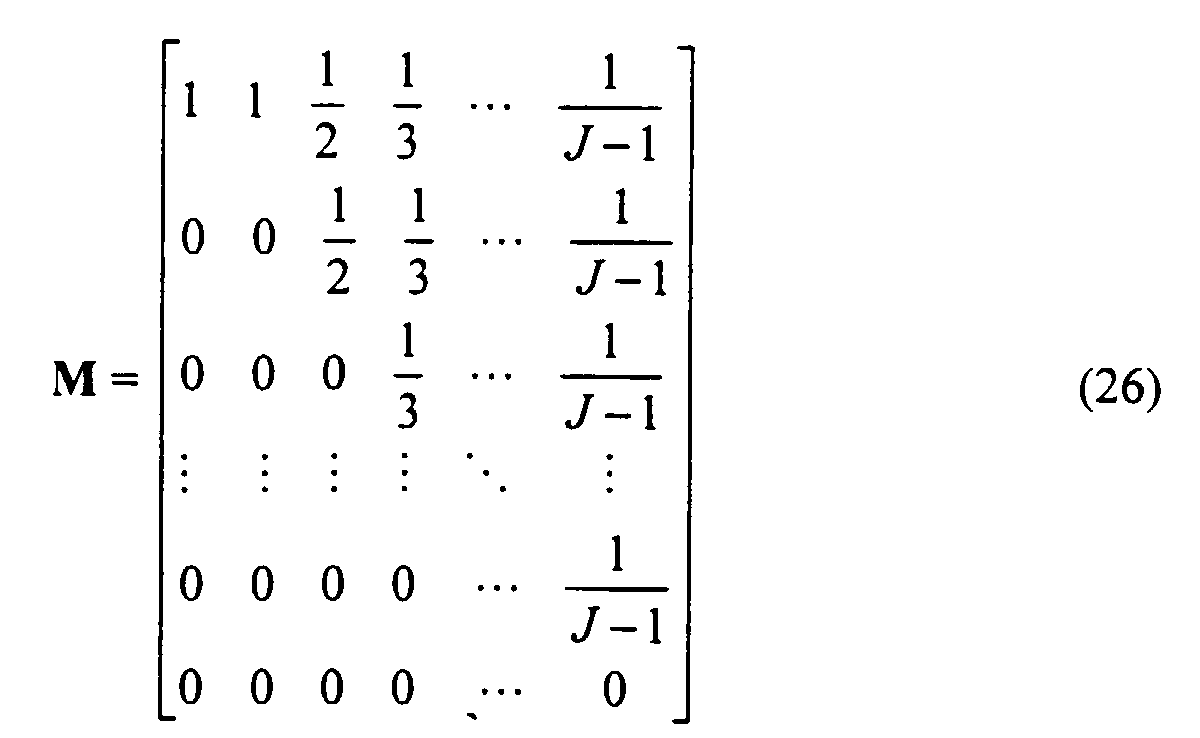
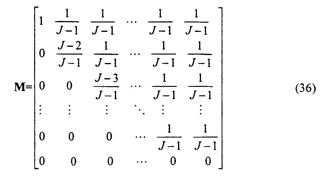
    We estimate the approximate number of blind searches in the algorithm and then compare this number to the number of blind searches required for the minimum SINR to reach a certain performance level. We first analyze the code assignment searching strategy in which all the possible code assignments are blindly searched until an assignment which achieves a better minimum SINR than the current assignment is found. p0 (j) is defined as the probability of picking the jth signature assignment. For a system using pseudo random codes, the probability distribution is given as p 0(j) = 1 / J, j = 1,2,...,J. Recall that the code assignments are sorted in ascending order. If the probability that the j1 -1 assignment gets picked next is zero, then the probability that any of the last J-j 1 assignments gets picked next is 1 / J-j 1. Therefore, the probability distribution after the first cycle of searches {p 1(j)} becomes p1 = Mp0, where p 0 = [p 0(J), p 0(J-1),...,p0(1)] T , p 1 = [p 1(J),p 1(J-1),...,p 1(1)] T , and the transition matrix M : J x J is defined as
    Figure 00200001
    From observing the structure of M, it is seen that this code assignment searching algorithm pushes the distribution of the minimum SINR toward the better side of performance. To further improve the minimum SINR, we can repeat the same searching strategy several times. If i search cycles are conducted, we can obtain a probability function pi given by p1 = M i p0 Note that once a good minimum SINR has been obtained, the number of searches required in each search cycle increases as the searching continues, since it is getting more difficult to find an even slightly better minimum SINR. The average number of blind searches required at the ith cycle can be written as
    Figure 00200002
    The number of possible signature assignments J is usually a large number. Therefore, equations (25), (27) and (28) are difficult to evaluate. Thus we need to rewrite these equations in a continuous form. Let the jth assignment be the bottom x(j) percent among J assignments, namely x = j / J, and let pi(x) be the probability density function of x after the ith search cycle. The probability density function after the first cycle of searching becomes
    Figure 00200003
    where "In" denotes the natural log. Similarly, the probability density function after the ith cycle of searching becomes
    Figure 00210001
    By solving equation (30), we obtain p i (x) = 1 i! (ln 11-x ) i , where i! denotes factorial i. The cumulative distribution function (CDF) of the minimum SINR after the ith cycle of searching can then be written as
    Figure 00210002
    In addition, the average number of blind searches in the ith search cycle can be written as
    Figure 00210003
    Fig. 5 shows the improvement of the probability density function of the minimum SINR using the random search technique of searching all possible codes until a code which is better than the current code is found. Each curve in the figure is labeled by the number of the search cycles. By comparing Fig. 3 with Fig. 5, the number of cycles of blind searches which are required to achieve a certain minimum SINR performance can be determined. Fig. 6 shows the number of blind search cycles required to reach certain performance levels for the two random search techniques. Section 602 of Fig. 6 shows the number of search cycles required to have 50, 90, and 99 percent chance for the search results to be among the top 10, 1 and 0.1 percent of performance of all possible code assignments for the first random search technique which searches until a better code is found. For example, to have a 90 percent chance to reach the top 1 percent of performance using the first random search technique, we need to search for a better assignment at least 7 times.
    As described above, the second search strategy is to randomly search through a fixed number of code assignments to find the code with the best minimum SINK. If we search through i possible code assignments, the probability of picking the jth assignment pi (j) is given by
    Figure 00220001
    However, if we use i - 1 pairwise comparisons to search through i possible code assignments and we allow the same code assignments to repeat within i assignments, we can modify pi (j) as follows: In each pairwise comparison, if the j th / 1 assignment is first used, there is a j 1-1 / J-1 chance that the j th / 1 assignment will be compared to an assignment with poorer minimum SINR, while there is a 1 / J-1 chance that the j th / 1 assignment will be compared to an assignment with better minimum SINR. Therefore, the probability of the first j 1 - 1 assignments getting picked next is zero; the probability of the same assignment getting picked next is j 1 / J-1 ; and the probability of any of the better assignments getting picked next is 1 / J-1 . Thus, we can write {pi } as p i = M i-1p0,i = 2,3,... where p 0 = [p 0(J),p 0(J-1),...,p 0(1)] T ,p i = [pi (J),pi (J-1),...,pi (1)] T , and the transition matrix M : J x J is defined as
    Figure 00220002
    Again, the structure of the matrix M shows that this code assignment searching algorithm pushes the distribution of the minimum SINR toward the better side of the performance. Because J is usually a large number, equation (35) is not easy to evaluate. Therefore, pI is expressed in a continuous form as
    Figure 00230001
    assuming p 0(x) = 1,x ∈ [0,1], and also
    Figure 00230002
    By solving equation (38), we obtain pi (x)= ixi -1. The CDF of the minimum SINR after searching through i signature assignments can then be written as pi , CDF(x) = xi .
    Fig. 7 shows the improvement of the probability density function of the minimum SINR using the second search strategy of searching through a fixed number of code assignments. Each curve in the figure is labeled by the number of assignments searched. Comparing Fig. 3 with Fig. 7, we can determine how many code assignments must be searched in order to achieve a certain minimum SINR performance. Section 604 of Fig. 6 shows the number of searches required to have 50, 90, and 99 percent chance for the search results to rank among top 10, 1 and 0.1 percent of performance of all possible code assignments using the second random search strategy.
    There is a trade-off between the minimum SINR performance and the convergence speed. In the described algorithm, the convergence criterion, the step-size of the gradient search, and the technique of picking a target wireless terminal can be controlled in order to adjust the algorithm complexity and convergence speed. If the complexity of the assignment searching procedure is increased, then the minimum SINR performance is expected to improve, while it might take more time for the algorithm to converge. This trade-off is investigated in order to determine how much increase in algorithm complexity is required to achieve a certain performance improvement. The number of equivalent blind searches n and in the proposed algorithm is estimated. Based on n and, and Figs. 5-7, the improvement on the minimum SINR among all the possible code assignments is evaluated.
    As described above, blind searches are generally inefficient regardless of the searching strategy used. In view of the above performance analysis, improvements for the searching techniques may be summarized as follows.
    The random searches and the gradient searches serve the respective purposes of region dividing and local regional searching in the signal space. The random search first looks for the regions where a higher minimum SINR is more likely to occur. This random search may be seen as dividing the signal space into small regions and then finding one of the best regions among other sub-optimal regions. The gradient search then searches for the best minimum SINR around the best local region determined by the random search. The number of random searches for the code of wireless terminal k is defined as n andg,k. If the best code assignment in the best region has higher minimum SINR than any code assignments within those sub-optimal regions, then the equivalent number of blind searches for wireless terminal k can be written as n k = n r,k n g,k (N+2). Equivalent gradient searches are assumed to be conducted for each of the sub-optimal regions although these gradient searches are actually omitted. Note the factor N + 2 in equation (41) represents the number of searches in each step of the gradient search; N searches for the code, and 2 searches for the transmission delay.
    With respect to target wireless terminal isolation and sequential packing, if the number of wireless terminals in the system is much less than the dimension of the signal space, it can be assumed that the code search for each wireless terminal is independent. In other words, we assume that the best code found while searching the best codes for wireless terminal k regardless of the codes of other wireless terminal, is also the best code for wireless terminal k when searching the best code assignments for all the wireless terminals. The main purpose of the sequential packing technique described above is to validate this assumption. Therefore, the overall equivalent number of blind searches n and in the algorithm is roughly given by
    Figure 00250001
    The estimation of n and in equation (42) is over-optimistic; however, it offers some insights into the relationship between the system performance and the algorithm complexity.
    The foregoing Detailed Description is to be understood as being in every respect illustrative and exemplary, but not restrictive, and the scope of the invention disclosed herein is not to be determined from the Detailed Description, but rather from the claims as interpreted according to the full breadth permitted by the patent laws. It is to be understood that the embodiments shown and described herein are only illustrative of the principles of the present invention and that various modifications may be implemented by those skilled in the art without departing from the scope and spirit of the invention.

    Claims (22)

    1. A method for assigning codes in a CDMA wireless communication system in which a plurality of wireless terminals communicate via a plurality of channels, said method comprising the steps of:
      determining characteristics of said plurality of channels; and
      assigning codes to said plurality of wireless terminals based on said characteristics of said channels.
    2. A method for use in a CDMA wireless communication system comprising the steps of:
      receiving channel characteristics of a plurality of wireless channels; and
      assigning codes to a plurality of wireless terminals based on said received channel characteristics.
    3. The method of claim 1 or 2 wherein said step of assigning codes comprises the steps of:
      choosing a target wireless terminal; and
      assigning a code to said target wireless terminal.
    4. The method of claim 1 or 2 wherein step of assigning a code to a target wireless terminal comprises the step of:
         performing a random code search to obtain an improved code for said target wireless terminal which is an improvement over a current code of said target wireless terminal.
    5. The method of claim 1 or 2 wherein said step of performing a random code search comprises the step of randomly searching available codes until an improved code is found.
    6. The method of claim 1 or 2 wherein said step of performing a random code search comprises the step of randomly searching a subset of available codes for the best code in said subset.
    7. The method of claim 1 or 2 further comprising the step of:
         performing a gradient search of codes in the signal space area surrounding said improved code.
    8. The method of claim 1 or 2 further comprising the step of:
         performing a gradient search of transmission delays for said improved code.
    9. The method of claim 1 or 2 further comprising the steps of:
      performing a gradient search of codes in the signal space area surrounding said improved code; and
      performing a gradient search of transmission delays for said improved code.
    10. The method of claim 1 or 2 further comprising the steps of:
      maintaining a processing set of said plurality of wireless terminals;
      individually assigning codes to said wireless terminals in said processing set; and
      adding a wireless terminal to said processing set when said step of individually assigning codes to said wireless terminals in said processing set has converged and repeating said step of individually assigning codes.
    11. The method of claim 1 or 2 further comprising the step of:
         transmitting said codes to said plurality of wireless terminals.
    12. Apparatus for communicating with a plurality of wireless terminals via a plurality of channels, said apparatus comprising:
      a channel estimator for determining channel characteristics; and
      a code optimizer for assigning codes to said plurality of wireless terminals based on said channel characteristics.
    13. Apparatus for communicating with a plurality of wireless terminals via a plurality of channels, said apparatus comprising:
      means for determining channel characteristics; and
      means for assigning codes to said plurality of wireless terminals based on said channel characteristics.
    14. The apparatus of claim 13 wherein said means for assigning codes comprises:
      means for choosing a target wireless terminal; and
      means for assigning a code to said target wireless terminal.
    15. The apparatus of claim 14 wherein said means for assigning a code to a target wireless terminal comprises:
         means for performing a random code search to obtain an improved code for said target wireless terminal which is an improvement over a current code of said target wireless terminal.
    16. The apparatus of claim 15 wherein said means for performing a random code search comprises means for randomly searching available codes until an improved code is found.
    17. The apparatus of claim 15 wherein said means for performing a random code search comprises means for randomly searching a subset of available codes for the best code in said subset.
    18. The apparatus of claim 15 further comprising:
         means for performing a gradient search of codes in the signal space area surrounding said improved code.
    19. The apparatus of claim 15 further comprising:
         means for performing a gradient search of transmission delays for said improved code.
    20. The apparatus of claim 15 further comprising:
      means for performing a gradient search of codes in the signal space area surrounding said improved code; and
      means for performing a gradient search of transmission delays for said improved code.
    21. The apparatus of claim 13 further comprising:
      means for maintaining a processing set of said plurality of wireless terminals;
      means for individually assigning codes to said wireless terminals in said processing set;
      means for adding one of said plurality of wireless terminals to said processing set when said step of individually assigning codes to said wireless terminals in said processing set has converged and repeating said step of individually assigning codes.
    22. The apparatus of claim 13 further comprising:
         means for transmitting said codes to said plurality of wireless terminals.
    EP00304341A 1999-06-04 2000-05-23 Code assignment in a CDMA wireless system Expired - Lifetime EP1058401B1 (en)

    Applications Claiming Priority (4)

    Application Number Priority Date Filing Date Title
    US13746299P 1999-06-04 1999-06-04
    US137462P 1999-06-04
    US09/353,460 US7035238B1 (en) 1999-06-04 1999-07-13 Code assignment in a CDMA wireless system
    US353460 1999-07-13

    Publications (3)

    Publication Number Publication Date
    EP1058401A2 true EP1058401A2 (en) 2000-12-06
    EP1058401A3 EP1058401A3 (en) 2001-06-27
    EP1058401B1 EP1058401B1 (en) 2004-02-04

    Family

    ID=26835271

    Family Applications (1)

    Application Number Title Priority Date Filing Date
    EP00304341A Expired - Lifetime EP1058401B1 (en) 1999-06-04 2000-05-23 Code assignment in a CDMA wireless system

    Country Status (9)

    Country Link
    US (1) US7035238B1 (en)
    EP (1) EP1058401B1 (en)
    JP (1) JP3756383B2 (en)
    KR (1) KR100711527B1 (en)
    CN (1) CN1276657A (en)
    AU (1) AU3783800A (en)
    BR (1) BR0002525A (en)
    CA (1) CA2310175A1 (en)
    DE (1) DE60008040T2 (en)

    Cited By (1)

    * Cited by examiner, † Cited by third party
    Publication number Priority date Publication date Assignee Title
    EP1592274A3 (en) * 2004-04-30 2006-08-02 Lucent Technologies Inc. Method of reusing spreading codes

    Families Citing this family (2)

    * Cited by examiner, † Cited by third party
    Publication number Priority date Publication date Assignee Title
    US6973314B2 (en) * 2001-09-28 2005-12-06 Arraycomm Llc. System and related methods for clustering multi-point communication targets
    CN100375414C (en) * 2002-10-17 2008-03-12 中兴通讯股份有限公司 A Method for Dynamic Optimal Allocation of Channelization Codes in Wideband Code Division Multiple Access Communication System

    Family Cites Families (22)

    * Cited by examiner, † Cited by third party
    Publication number Priority date Publication date Assignee Title
    IL100213A (en) * 1990-12-07 1995-03-30 Qualcomm Inc CDMA microcellular telephone system and distributed antenna system therefor
    US5260968A (en) * 1992-06-23 1993-11-09 The Regents Of The University Of California Method and apparatus for multiplexing communications signals through blind adaptive spatial filtering
    US5461610A (en) * 1992-08-31 1995-10-24 At&T Ipm Corp. Precoding of signature sequences for CDMA systems
    MY112371A (en) * 1993-07-20 2001-05-31 Qualcomm Inc System and method for orthogonal spread spectrum sequence generation in variable data rate systems
    GB2285900A (en) 1993-12-23 1995-07-26 Motorola Ltd Communications system
    FI105512B (en) * 1995-05-24 2000-08-31 Nokia Networks Oy Method of providing possible angular diversity and base station device
    US5717406A (en) * 1995-06-07 1998-02-10 Sanconix Inc. Enhanced position calculation
    US5764687A (en) * 1995-06-20 1998-06-09 Qualcomm Incorporated Mobile demodulator architecture for a spread spectrum multiple access communication system
    JPH1051354A (en) * 1996-05-30 1998-02-20 N T T Ido Tsushinmo Kk DS-CDMA transmission method
    US5790589A (en) * 1996-08-14 1998-08-04 Qualcomm Incorporated System and method for rapidly reacquiring a pilot channel
    US5889768A (en) * 1996-08-30 1999-03-30 Motorola, Inc. Method of and apparatus for pilot channel acquisition
    US5831977A (en) * 1996-09-04 1998-11-03 Ericsson Inc. Subtractive CDMA system with simultaneous subtraction in code space and direction-of-arrival space
    FI964138L (en) 1996-10-15 1998-04-16 Nokia Telecommunications Oy Channel allocation method and radio system
    US5883612A (en) * 1996-10-24 1999-03-16 Motorola, Inc. Method for positioning a vibrating alert adjacent to a selected alert in selective call device
    JP3270015B2 (en) * 1997-11-19 2002-04-02 沖電気工業株式会社 Transmission power control device
    KR100279944B1 (en) * 1997-12-09 2001-02-01 윤종용 Method of walsh code allocation by group in cdma cellular system
    US6061339A (en) * 1997-12-10 2000-05-09 L-3 Communications Corporation Fixed wireless loop system having adaptive system capacity based on estimated signal to noise ratio
    JP2918873B1 (en) * 1998-02-17 1999-07-12 株式会社エイ・ティ・アール環境適応通信研究所 Array antenna device for spread spectrum communication
    FR2784525B1 (en) * 1998-10-12 2006-07-28 Cit Alcatel PROCESS FOR ALLOCATING ORTHOGONAL CODES IN A MOBILE RADIOCOMMUNICATIONS SYSTEM OF THE MULTIPLE ACCESS TYPE BY CODES DISTRIBUTION USING CODES OF VARIABLE LENGTH
    US6163524A (en) * 1998-10-19 2000-12-19 Telefonaktiebolaget Lm Ericsson (Publ) Code allocation in CDMA
    US6504827B1 (en) * 1998-12-18 2003-01-07 Lucent Technologies Inc. Discontinuous transmission on high speed data channels
    US6259924B1 (en) * 1999-12-30 2001-07-10 Motorola, Inc. Method and system for comparing measured radio frequency signal propagation characteristics in a wireless communication system

    Cited By (2)

    * Cited by examiner, † Cited by third party
    Publication number Priority date Publication date Assignee Title
    EP1592274A3 (en) * 2004-04-30 2006-08-02 Lucent Technologies Inc. Method of reusing spreading codes
    EP1784033A1 (en) * 2004-04-30 2007-05-09 Lucent Technologies Inc. Method of reusing spreading codes

    Also Published As

    Publication number Publication date
    AU3783800A (en) 2000-12-07
    BR0002525A (en) 2001-03-13
    KR20010007208A (en) 2001-01-26
    US7035238B1 (en) 2006-04-25
    JP2001016185A (en) 2001-01-19
    EP1058401B1 (en) 2004-02-04
    DE60008040T2 (en) 2004-08-26
    EP1058401A3 (en) 2001-06-27
    DE60008040D1 (en) 2004-03-11
    CN1276657A (en) 2000-12-13
    JP3756383B2 (en) 2006-03-15
    KR100711527B1 (en) 2007-04-27
    CA2310175A1 (en) 2000-12-04

    Similar Documents

    Publication Publication Date Title
    US7656936B2 (en) Method and system for interference reduction in a wireless communication network using a joint detector
    JP3553426B2 (en) Method for directly detecting a data signal modulated by a spread spectrum signal
    US5572552A (en) Method and system for demodulation of downlink CDMA signals
    US5757845A (en) Adaptive spread spectrum receiver
    US6512737B1 (en) Stacked carrier discrete multiple tone communication system
    US6529545B2 (en) Rake receiver
    US7778355B2 (en) Space-time transmit diversity
    US6721293B1 (en) Unsupervised adaptive chip separation filter for CDMA terminal
    US20050009476A1 (en) Virtual MIMO transmitters, receivers, systems and methods
    EP1523120A2 (en) Methods and apparatus for downlink diversity in cdma using walsh codes
    WO2000011823A1 (en) Stacked-carrier discrete multiple tone communication technology
    Sethi et al. Code reuse DS-CDMA-a space time approach
    EP3557771B1 (en) Interference suppression method and device, and computer storage medium
    WO2000054418A1 (en) Unsupervised adaptive chip separation filter for cdma terminal
    EP1058401B1 (en) Code assignment in a CDMA wireless system
    Zhang et al. Optimal space-time transceiver design for selective wireless broadcast with channel state information
    Shakya et al. High user capacity collaborative code-division multiple access
    Zvonar Multiuser detection and diversity combining for wireless CDMA systems
    Borah et al. Optimal adaptive multiuser detection in unknown multipath channels
    Buzzi et al. Single-antenna blind receiver for multiuser detection in unknown correlated noise
    Pelletier et al. Group-based space-time multiuser detection with user sharing
    CN103684522B (en) A kind of method and apparatus of multi-cell joint detection
    Gopalan et al. Capacity, throughput, and delay of slotted Aloha DS-CDMA links with adaptive space-time auxiliary-vector receivers
    Missaoui et al. Throughput Enhancement in Wireless Slotted ALOHA via collision processing
    da Silva et al. Interference Cancellation with combined Pre-distortion filtering and Transmit Diversity

    Legal Events

    Date Code Title Description
    PUAI Public reference made under article 153(3) epc to a published international application that has entered the european phase

    Free format text: ORIGINAL CODE: 0009012

    17P Request for examination filed

    Effective date: 20000602

    AK Designated contracting states

    Kind code of ref document: A2

    Designated state(s): DE FI GB SE

    AX Request for extension of the european patent

    Free format text: AL;LT;LV;MK;RO;SI

    PUAL Search report despatched

    Free format text: ORIGINAL CODE: 0009013

    RIN1 Information on inventor provided before grant (corrected)

    Inventor name: CHEN, JIUNN-TSAIR

    Inventor name: PAPADIAS, CONSTANTINOS BASIL

    Inventor name: FOSCHINI, GERARD JOSEPH

    AK Designated contracting states

    Kind code of ref document: A3

    Designated state(s): AT BE CH CY DE DK ES FI FR GB GR IE IT LI LU MC NL PT SE

    AX Request for extension of the european patent

    Free format text: AL;LT;LV;MK;RO;SI

    17Q First examination report despatched

    Effective date: 20010726

    AKX Designation fees paid

    Free format text: DE FI GB SE

    GRAP Despatch of communication of intention to grant a patent

    Free format text: ORIGINAL CODE: EPIDOSNIGR1

    GRAS Grant fee paid

    Free format text: ORIGINAL CODE: EPIDOSNIGR3

    GRAA (expected) grant

    Free format text: ORIGINAL CODE: 0009210

    AK Designated contracting states

    Kind code of ref document: B1

    Designated state(s): DE FI GB SE

    REG Reference to a national code

    Ref country code: GB

    Ref legal event code: FG4D

    REF Corresponds to:

    Ref document number: 60008040

    Country of ref document: DE

    Date of ref document: 20040311

    Kind code of ref document: P

    REG Reference to a national code

    Ref country code: SE

    Ref legal event code: TRGR

    PLBE No opposition filed within time limit

    Free format text: ORIGINAL CODE: 0009261

    STAA Information on the status of an ep patent application or granted ep patent

    Free format text: STATUS: NO OPPOSITION FILED WITHIN TIME LIMIT

    26N No opposition filed

    Effective date: 20041105

    REG Reference to a national code

    Ref country code: GB

    Ref legal event code: 732E

    Free format text: REGISTERED BETWEEN 20131107 AND 20131113

    PGFP Annual fee paid to national office [announced via postgrant information from national office to epo]

    Ref country code: DE

    Payment date: 20160520

    Year of fee payment: 17

    Ref country code: FI

    Payment date: 20160511

    Year of fee payment: 17

    Ref country code: GB

    Payment date: 20160520

    Year of fee payment: 17

    PGFP Annual fee paid to national office [announced via postgrant information from national office to epo]

    Ref country code: SE

    Payment date: 20160519

    Year of fee payment: 17

    REG Reference to a national code

    Ref country code: DE

    Ref legal event code: R119

    Ref document number: 60008040

    Country of ref document: DE

    REG Reference to a national code

    Ref country code: SE

    Ref legal event code: EUG

    GBPC Gb: european patent ceased through non-payment of renewal fee

    Effective date: 20170523

    PG25 Lapsed in a contracting state [announced via postgrant information from national office to epo]

    Ref country code: FI

    Free format text: LAPSE BECAUSE OF NON-PAYMENT OF DUE FEES

    Effective date: 20170523

    PG25 Lapsed in a contracting state [announced via postgrant information from national office to epo]

    Ref country code: SE

    Free format text: LAPSE BECAUSE OF NON-PAYMENT OF DUE FEES

    Effective date: 20170524

    PG25 Lapsed in a contracting state [announced via postgrant information from national office to epo]

    Ref country code: GB

    Free format text: LAPSE BECAUSE OF NON-PAYMENT OF DUE FEES

    Effective date: 20170523

    Ref country code: DE

    Free format text: LAPSE BECAUSE OF NON-PAYMENT OF DUE FEES

    Effective date: 20171201