EP1058356A2 - Socket assembly - Google Patents
Socket assembly Download PDFInfo
- Publication number
- EP1058356A2 EP1058356A2 EP00112099A EP00112099A EP1058356A2 EP 1058356 A2 EP1058356 A2 EP 1058356A2 EP 00112099 A EP00112099 A EP 00112099A EP 00112099 A EP00112099 A EP 00112099A EP 1058356 A2 EP1058356 A2 EP 1058356A2
- Authority
- EP
- European Patent Office
- Prior art keywords
- housing
- lamp
- disc
- idc
- lamp socket
- Prior art date
- Legal status (The legal status is an assumption and is not a legal conclusion. Google has not performed a legal analysis and makes no representation as to the accuracy of the status listed.)
- Withdrawn
Links
- 238000000034 method Methods 0.000 claims description 11
- 238000007789 sealing Methods 0.000 claims 1
- 230000014759 maintenance of location Effects 0.000 description 9
- 238000003466 welding Methods 0.000 description 3
- 238000009413 insulation Methods 0.000 description 2
- 239000012212 insulator Substances 0.000 description 2
- RYGMFSIKBFXOCR-UHFFFAOYSA-N Copper Chemical compound [Cu] RYGMFSIKBFXOCR-UHFFFAOYSA-N 0.000 description 1
- 238000011109 contamination Methods 0.000 description 1
- 230000003247 decreasing effect Effects 0.000 description 1
- 238000006073 displacement reaction Methods 0.000 description 1
- 238000003780 insertion Methods 0.000 description 1
- 230000037431 insertion Effects 0.000 description 1
- 239000000463 material Substances 0.000 description 1
- 230000013011 mating Effects 0.000 description 1
- 239000002184 metal Substances 0.000 description 1
- 229910052751 metal Inorganic materials 0.000 description 1
- 238000012986 modification Methods 0.000 description 1
- 230000004048 modification Effects 0.000 description 1
- 239000002991 molded plastic Substances 0.000 description 1
Images



Classifications
-
- H—ELECTRICITY
- H01—ELECTRIC ELEMENTS
- H01R—ELECTRICALLY-CONDUCTIVE CONNECTIONS; STRUCTURAL ASSOCIATIONS OF A PLURALITY OF MUTUALLY-INSULATED ELECTRICAL CONNECTING ELEMENTS; COUPLING DEVICES; CURRENT COLLECTORS
- H01R33/00—Coupling devices specially adapted for supporting apparatus and having one part acting as a holder providing support and electrical connection via a counterpart which is structurally associated with the apparatus, e.g. lamp holders; Separate parts thereof
- H01R33/05—Two-pole devices
- H01R33/06—Two-pole devices with two current-carrying pins, blades or analogous contacts, having their axes parallel to each other
Definitions
- the present invention relates to a lamp socket, more particularly to an insulation displacement connector (IDC) wedge base angled lamp socket for a wedge based lamp used in a lighting module of a motor vehicle.
- This angled lamp socket of the present invention is particularly useful in front and rear automobile directional and safety lighting.
- a lamp socket wherein the horizontal axis of the lamp inserted therein extends in one direction and the terminals of the lamp socket extend in another direction and at an angle thereto is well known.
- a lamp socket is herein referred to as an angled lamp socket.
- One such angled lamp socket is referred to in the lamp industry as a right angle lamp socket.
- the horizontal axis of the lamp and the terminals of the lamp socket are orientated at 90° relative to each other.
- an angled lamp socket that comprises a body having a housing attached thereto. At least one lamp retaining member is provided within the body and is structured to retain a lamp that has a longitudinal lamp axis, such that the lamp axis will extend in a first direction when the lamp is inserted into the body. A plurality of "U" shaped IDC contacts is provided such that at least a portion of each is in the socket body with a portion extending beyond the bottom of the body. A socket housing disc, containing a plurality of slits to receive the portion of the IDC terminals protruding below the socket body, will be placed into the housing.
- the disc will contain a plurality of small finger-like projections on the rear of the disc that will place a normal force on wire leads placed into the housing.
- the disc will also contain a center post to help secure the disc in the housing and a plurality of holes through which molded projections from the bottom of the body will go to place strain relief on the wires.
- the housing contains a plurality of holes through which wires will be inserted.
- the floor of the housing will contain a plurality of grooves in which the wires will sit as they are inserted into the housing. These wires will be inserted in a second direction which will be at an angle to the first direction.
- Each wire will be fed through a hole into the housing where it will be held in place by the finger-like projections of the housing disc to prevent easy removal of the wires.
- the IDC terminals securely located in the body and guided by the slits in the housing disc, terminate the wires at the same time that molded projections from the rear of the socket body put strain relief on the wires.
- a method for assembling an angled lamp socket is also provided.
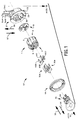
- FIG. 1 illustrates a lamp socket 57 embodying the present invention.
- Lamp socket 57 provides a three piece insulator that is in the form of first, second and third slidably engaging components including a body 1, a housing disc 13 , and a housing 21.
- the three-piece insulator simplifies design and assembly of the lamp socket.
- the body component includes a body cavity 5 that extends in a direction 50 of axis 52.
- the housing disc 13 (Fig. 3) contains a plurality of slits 16A, B, C and D. These slits receive the bottom portion 42 of the IDC contacts 40A, B, C and D (shown in Fig. 9) guiding them to a position just above the wire leads 54A,B and C at an approximate distance of 5.3 mm.
- the housing 21 includes a cavity 30 that opens in direction 58 of axis 52 and a plurality of holes 29A, B and C, the holes extending in the direction 59 of axis 53.
- the axis 52 extends at an angle to the axis 53. In the preferred embodiment illustrated in FIG. 7, the angle is 90°, and the angled lamp socket is a right angle lamp socket.
- the body and the housing disc are connected to the housing as described hereinafter.
- the lamp socket 57 includes two lamp-retaining members in the form of a first resilient retention member 35A and an opposite second resilient retention member 35B.
- the resilient retention members are metal, although other materials may be used.
- Retention members 35A and 35B are structured and arranged for insertion into the body cavity 5 to retain a wedge-like base 60 of a lamp 55, such as a conventional S8 wedge base lamp, so that the lamp longitudinal axis 52 extends in the first direction 50 when the lamp is inserted in the body cavity.
- the lamp socket 57 includes a plurality of IDC contacts 40A, B, C and D, in the body cavity 5.
- each IDC contact is "U" shaped, although other shapes may be used.
- Each IDC contact 40 includes a top end 41 and a bottom end 42. The top end 41 faces the front end 2 of the body 1 and is adapted to engage a respective lead 56 of lamp 55.
- the bottom end 42 extends out of the body 1 at the rear end 3 of said body and is adapted to terminate a wire lead.
- the lamp socket includes wire leads 54A, B and C, which are inserted into the holes 29 A, B and C in the housing 21.
- Each wire lead is inserted into a hole in the housing and is guided by a groove 24 in the floor of the housing to its final position.
- the housing disc 13 is snapped into the housing cavity 30 in the first direction.
- Wire leads 54A, B and C, are inserted into the holes in the housing in the second direction.
- the wire leads deflect up finger-like projections (not shown) on the rear of the housing disc 13, these finger-like projections exerting a normal force on the wire leads 54A, B and C, to prevent easy removal of said wire leads. A force is exerted on the front of the body 1 in the first direction.
- the bottom portion of the IDC contacts 42A, B, C and D pass through the slits 16A, B, C and D, in the housing disc 13 and terminate the wire leads 54A, B and C, providing an electrical connection.
- the bottom portion of the IDC contacts engage detents 25 in the floor 32 of the housing 21 upon termination of the wire leads 54.
- molded protrusions 7A, B and C, on the rear of the body 1 pass through holes 17A, B and C, in the housing disc 13 and engage the wire leads 54A, B and C, providing strain relief on said wire leads.
- FIG. 2 shows the body 1 with rear portion 3 having a plurality of molded projections extending in direction 50 of axis 52.
- Apertures 10A, B, C and D, on the rear 3 of the body 1 allow the bottom 42 of each IDC contact member 40A, B, C and D, to extend below the body.
- a notch 12 on one side of the body 1 contacts a vertical rib 28 on the interior wall surface 61 of the housing cavity 30 helping guide the body into its proper position in the housing cavity.
- Detents 8 and 9 on the outside surface 4 of the body 1 engage ribs 26 and 27 on the interior surface of the housing cavity 21 securing the body in said housing.
- Slots 11A, B, C and D, in the front of the body cavity 5 receive the lamp retention members 35A and 35B securing them in the body cavity.
- FIG. 3 shows the housing disc 13 with slits 16A,B,C and D to receive the bottom portion 42 of the IDC contact members 40.
- Holes 29A, B and C, receive the molded projections 7A, B and C, extending from the rear 3 of the body 1 and the top view of the finger-like projections (not shown) that extend from the rear 15 of the housing disc 13, the finger-like projections providing a normal force on the wire leads 54A, B and C, inserted into the housing thereby preventing easy removal of said wire leads.
- a notch 20 on the side of the housing disc contacts a vertical rib 28 on the inside surface of the housing cavity 30 helping to guide the disc into position.
- the center post 18 (see Fig. 5) on the rear of the housing disc engages a detent 34 (see Fig. 5) in the floor of the housing 21. The disc snaps into position engaging rib 27 on the inside surface of said housing.
- FIG 4 shows the housing 21 with a cavity 30 extending in direction 58 of axis 52 and a plurality of holes 29A,B, and C extending in direction 59 of axis 53 through which wire leads 54A, B and C, are inserted.
- the wire leads 54A, B, and C, are guided into place by grooves 24 in the floor of the housing 21.
- Vertical rib 28 aligns with the notch 20 on the housing disc 13 as it is snapped into the housing cavity 30.
- Rib 27 (not shown) holds the housing disc in place.
- rib 26 engages detent 8 on the body's outside surface 4 so that the IDC contact members 40A, B, C and D, are positioned just in the slits 16A, B, C and D, of the housing disc 13 at a position approximately 5.3 mm from the wire leads 54A,B and C.
- the surface 23 of the flange 22 receives the annular seal 44 and the inside surface of the flange 49 engages the outside surface 4 of the body 1.
- FIG. 5 shows a cross section of the completed lamp socket 57.
- the body 1, containing lamp retention members 35A and 35B, is snapped into the housing 21.
- the housing disc 13 has center post 18 which engages a detent 34 in the floor 32 of the housing 21.
- the annular seal 44 engages the front surface 23 of the flange 22.
- FIG. 6 shows a cross section of the completed lamp socket 57.
- a wire lead 54 is placed into a hole 29 of the housing 21 at the second direction.
- the wire lead is guided by a groove 24 in the floor 32 of the housing deflecting up a finger-like projection 19 on the rear of the housing disc 13 preventing the wire lead from being easily removed.
- a force is exerted on the body 1 in the first direction.
- the bottom portion 42 of an IDC contact 40A passes through one of the slits 16 in the housing disc 13 and terminates the wire lead 54 while a molded projection 7 from the rear of the body 1 passes through a hole 17 in the housing disc 13 and engages the wire lead 54 providing strain relief.
- ribs 26 and 27 located on the inside surface 61 of the housing 21, engage notches 8 and 9, located on the outside surface 4 of the body 1, securing the body inside the housing.
- FIG. 7 shows a completed angled lamp socket 57 with a lamp 55 not attached.
- the lamp 55 is inserted into the lamp socket body 1 in a first direction and is held in place by lamp retention members 35A and 35B. Angled portions 37 of the lamp retention members 35 engage the lamp base 60 thereby securing the lamp in the body cavity 5.
- Wire leads 54A, B and C extend from the housing in the second direction thereby creating an angled lamp socket.
- the lamp terminals 56 contact the top portion 41 of the IDC contacts creating an electrical connection between the lamp and the IDC contacts.
- the bottom portion 42 of the IDC contacts terminate the wire leads 54A, B and C,, as shown in Fig. 6, providing an electrical connection between the IDC contacts and the wire lead. This allows the lamp terminals 56 to be electrically connected to the same IDC contacts 40A, B, C and D, that terminate the wire leads 54A, B and C, eliminating welding in the housing and the need for additional sets of contact members.
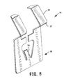
- FIG. 8 shows a lamp retainer clip 35 with a bottom portion 38 and a small finger projection 39 which holds the retainer clip in the body cavity 5 when said small finger projection 39 contacts a detent in the body cavity.
- Top portions 36 contain an angled bend 37 which, when placed in the body cavity 5 secure the lamp 55.
- FIG. 9 shows a U-shaped IDC contact 40.
- the top portion 41 engages the leads 56 of the lamp 55 thereby creating an electrical connection.
- the IDC contact also contains shoulders 43 which engage portions of the body cavity 5 to keep the IDC contact in place.
- the bottom portion 42 of the IDC contact 40 is shaped so as to allow it to terminate a wire lead 54 by cutting through the insulation and engaging the copper wire thereby creating an electrical connection.
- an angled lamp socket that is economical to fabricate.
- the need for welding, with its concomitant contamination, is eliminated.
- the number of contacts is minimized by utilizing the socket wire-lead contact as a direct connection to the lamp.
Landscapes
- Fastening Of Light Sources Or Lamp Holders (AREA)
- Connecting Device With Holders (AREA)
Abstract
Description
Claims (20)
- An angled lamp socket, comprising:a body having a front end and a rear end;a housing disc having a front end and a rear end, said front end being attached to the rear end of the body;a housing attached to said housing disc at said rear end;at least one lamp retaining member within said body and structured and arranged to retain a lamp having a longitudinal lamp axis inserted into said body at the front end such that said longitudinal lamp axis of said lamp will extend in a first direction when the lamp is inserted in the body;a plurality of IDC contacts at least a portion of each that is in the body, each IDC contact capable of terminating a wire lead; anda plurality of holes in the housing at a second direction, said second direction being at an angle to the first direction.
- An angled lamp socket, comprising;a body having a body cavity extending in a first direction of a first axis from a front end to rear end;a housing disc having a plurality of slits capable of receiving the bottom portion of at least one IDC contact;a housing having a housing cavity extending in the first direction and a plurality of holes extending through said housing in a second direction such that the second direction is at an angle to said first direction;at least one lamp retaining member at least a portion of which is in said body cavity, said lamp retaining member being structured and arranged to retain a lamp having a longitudinal lamp axis to be inserted in said body cavity at said front end such that said longitudinal lamp axis of said lamp will extend in said first direction when said lamp is inserted in said body cavity; anda plurality of IDC contacts such that a portion of each IDC contact is in the body cavity and a portion of each IDC contact extends below said body cavity and is capable of terminating a wire lead;
- The angled lamp socket of claim 2 wherein each IDC contact comprises a bottom portion capable of terminating a wire and creating an electrical connection.
- The angled lamp socket of claim 2 wherein the body cavity comprises at least one detent, and each IDC contact comprises a projection that engages a detent and each projection being structured and arranged to maintain alignment of said IDC contact during its termination of a wire lead.
- The IDC contact of claim 4 wherein said IDC contact comprises a top portion capable of engaging a lead from a lamp and creating an electrical connection.
- The angled lamp socket of claim 2 wherein the housing further comprises grooves on the floor of the housing capable of guiding wire leads.
- The angled lamp socket of claim 2 wherein the housing cavity extending in the first direction comprises a flange, and further including an annular seal through that the body extends, said annular seal being structured and arranged to have a first surface that sealingly engages said flange, and a second surface that sealingly engages an outer surface of said body, in a use mode of said angled lamp socket.
- The angled lamp socket of claim 2 wherein the housing further comprises at least one rib which engages the housing disc when said disc is inserted into said housing cavity.
- The angled lamp socket of claim 2 wherein said housing disc further comprises a molded post on the rear side of the disc that engages a detent in the housing when the disc is snapped into said housing.
- The housing disc of claim 9 wherein said rear of said housing disc further comprises plastic molded finger-like projections capable of placing a normal force on a wire lead.
- The angled lamp socket of claim 2 wherein the rear of said body further comprises a plurality of molded projections capable of placing a force on a wire lead to provide strain relief.
- A method for assembling an angled lamp socket of the type wherein a longitudinal lamp axis of a lamp to be inserted into the front end of an angled lamp socket will extend at an angle to a plurality of wire leads to be placed into the housing, comprising the steps of:inserting the housing disc into the housing such that said housing disc snaps into said housing with the molded post on the rear surface of said housing disc contacting the rear portion of said housing; andinserting a plurality of IDC contacts into the body cavity such that a contact lead surface of each IDC contact extends away from the front of said body and a bottom portion of each IDC contact member extends below the rear of said body;
- The method of claim 12 further including the step of attaching the body to the housing.
- The method of claim 13 wherein the body is of the type wherein said body cavity comprises a front end into which a lamp may be inserted and an opposite rear end, said step of inserting a portion of said body into the housing cavity comprising the step of snapping said rear end of said body into the housing cavity such that said rear of said body snaps into place in said housing such that the bottom of the IDC contacts are approximately 5.3mm from the wire leads.
- The method of claim 12 further including the step of sealing said IDC contact members within the housing.
- The method of claim 15 wherein the housing is a type that includes a flange adjacent to said housing cavity, and an annular gasket, and further including the step of inserting said portion of said body through said annular gasket before the step of inserting said portion of said body into said housing cavity.
- The method of claim 12 further including the step of inserting wire leads into the apertures in the housing.
- The method of claim 17 further comprising the step of inserting a plurality of wire leads into the holes in the housing in a second direction that is at an angle to the first direction, said wire leads entering the housing and being guided by said grooves in the bottom of said housing and deflecting said finger-like projections protruding from the rear of the housing disc such that said finger-like projections exert a normal force on said wire leads providing resistance against easy removal of said wire leads.
- The method of claim 12 further including the step of terminating the wire leads with the IDC Lamp contact members.
- The method of claim 19 further comprising the step of exerting a force on the body in the first direction causing said body to snap further into the housing such that the rear portion of the body makes contact with the front of the housing disc, the IDC contacts pass through the slits in said housing disc and terminate the wire leads creating an electrical contact, and the plastic molded portions protruding from the rear of said body pass through the holes in said housing disc and engage the wire leads to provide strain relief on said wire leads.
Applications Claiming Priority (4)
| Application Number | Priority Date | Filing Date | Title |
|---|---|---|---|
| US13755499P | 1999-06-04 | 1999-06-04 | |
| US137554P | 1999-06-04 | ||
| US09/548,508 US6250970B1 (en) | 1999-06-04 | 2000-04-13 | Angled IDC lamp socket assembly |
| US548508 | 2000-04-13 |
Publications (2)
| Publication Number | Publication Date |
|---|---|
| EP1058356A2 true EP1058356A2 (en) | 2000-12-06 |
| EP1058356A3 EP1058356A3 (en) | 2001-02-28 |
Family
ID=26835355
Family Applications (1)
| Application Number | Title | Priority Date | Filing Date |
|---|---|---|---|
| EP00112099A Withdrawn EP1058356A3 (en) | 1999-06-04 | 2000-06-05 | Socket assembly |
Country Status (3)
| Country | Link |
|---|---|
| US (1) | US6250970B1 (en) |
| EP (1) | EP1058356A3 (en) |
| CA (1) | CA2306025A1 (en) |
Cited By (3)
| Publication number | Priority date | Publication date | Assignee | Title |
|---|---|---|---|---|
| WO2005076317A3 (en) * | 2004-02-09 | 2005-10-06 | Patent Treuhand Ges Fuer Elektrische Gluehlampen Mbh | Vehicle headlight bulb |
| FR2873503A1 (en) * | 2004-07-20 | 2006-01-27 | Const Electromecaniques Thome | Lamp holder for motor vehicle headlight, has electrical connectors, each made of single unit and presenting, in plane perpendicular to axial direction of cavity, dimension lesser than cavity |
| EP1851834A4 (en) * | 2005-02-21 | 2008-08-06 | Tyco Electronics Canada Ltd | COVERED LAMP SLEEVE |
Families Citing this family (13)
| Publication number | Priority date | Publication date | Assignee | Title |
|---|---|---|---|---|
| US6398385B1 (en) * | 2000-04-11 | 2002-06-04 | Chi-Hua Lin | Fixed-device for the bulb socket |
| US6467942B2 (en) * | 2001-01-12 | 2002-10-22 | Alcoa Fujikura Limited | Automotive lamp socket |
| US6443769B1 (en) * | 2001-02-15 | 2002-09-03 | General Electric Company | Lamp electronic end cap for integral lamp |
| JP2003132983A (en) * | 2001-10-22 | 2003-05-09 | Yazaki Corp | Combination lamp connection structure |
| USD492934S1 (en) | 2002-01-29 | 2004-07-13 | Bjb Gmbh & Co. Kg | Lamp socket and cap |
| US6692309B1 (en) * | 2003-03-28 | 2004-02-17 | Light Sources, Inc. | Mercury vapor lamp electrical connector |
| KR100791533B1 (en) * | 2006-04-14 | 2008-01-04 | 주식회사 신광하이테크 | Light bulb socket |
| JP4851309B2 (en) * | 2006-12-06 | 2012-01-11 | 矢崎総業株式会社 | Lighting device |
| US7604506B2 (en) * | 2006-12-29 | 2009-10-20 | Empire Electronics, Inc. | Lamp socket assemblies with axial terminals |
| EP2012176A1 (en) * | 2007-07-02 | 2009-01-07 | Heesung Electronics Co., Ltd. | Power connection apparatus of direct type backlight unit |
| CN101615750B (en) * | 2008-06-24 | 2011-03-16 | 上海小糸车灯有限公司 | Contact-type lamp holder for wedge-shaped bulb |
| JP2013037989A (en) * | 2011-08-10 | 2013-02-21 | Yazaki Corp | Socket |
| CN204943397U (en) * | 2015-07-22 | 2016-01-06 | 厦门广泓工贸有限公司 | LED drive plate and lamp holder electric connection terminal and electric connector and LED |
Family Cites Families (7)
| Publication number | Priority date | Publication date | Assignee | Title |
|---|---|---|---|---|
| GB8514690D0 (en) | 1985-06-11 | 1985-07-10 | Amp Great Britain | Holder for lamp bulb |
| US5197187A (en) | 1991-09-30 | 1993-03-30 | Gte Products Corporation | Lamp socket and method for fabricating same |
| NL9300386A (en) * | 1992-09-23 | 1994-10-03 | Whitaker Corp | Electrical connector and electrical terminal therefor. |
| JP3127428B2 (en) | 1994-06-14 | 2001-01-22 | 株式会社小糸製作所 | Vehicle lighting |
| JPH10125408A (en) * | 1996-10-17 | 1998-05-15 | Dai Ichi Denshi Kogyo Kk | Connector device |
| FR2768864B1 (en) | 1997-09-25 | 1999-11-19 | Framatome Connectors Int | ELECTRICAL CONNECTOR FOR LIGHTING DEVICE |
| US5971814A (en) * | 1998-09-08 | 1999-10-26 | Osram Sylvania Inc. | Lamp socket |
-
2000
- 2000-04-13 US US09/548,508 patent/US6250970B1/en not_active Expired - Lifetime
- 2000-04-18 CA CA002306025A patent/CA2306025A1/en not_active Abandoned
- 2000-06-05 EP EP00112099A patent/EP1058356A3/en not_active Withdrawn
Cited By (4)
| Publication number | Priority date | Publication date | Assignee | Title |
|---|---|---|---|---|
| WO2005076317A3 (en) * | 2004-02-09 | 2005-10-06 | Patent Treuhand Ges Fuer Elektrische Gluehlampen Mbh | Vehicle headlight bulb |
| US7659656B2 (en) | 2004-02-09 | 2010-02-09 | Osram Gesellschaft Mit Beschraenkter Haftung | Vehicle headlight bulb |
| FR2873503A1 (en) * | 2004-07-20 | 2006-01-27 | Const Electromecaniques Thome | Lamp holder for motor vehicle headlight, has electrical connectors, each made of single unit and presenting, in plane perpendicular to axial direction of cavity, dimension lesser than cavity |
| EP1851834A4 (en) * | 2005-02-21 | 2008-08-06 | Tyco Electronics Canada Ltd | COVERED LAMP SLEEVE |
Also Published As
| Publication number | Publication date |
|---|---|
| EP1058356A3 (en) | 2001-02-28 |
| CA2306025A1 (en) | 2000-12-04 |
| US6250970B1 (en) | 2001-06-26 |
Similar Documents
| Publication | Publication Date | Title |
|---|---|---|
| US6250970B1 (en) | Angled IDC lamp socket assembly | |
| US5399110A (en) | Two piece male pin terminal | |
| JPH07118346B2 (en) | Sealed electrical connector | |
| US7563135B2 (en) | Connector | |
| JPH07282892A (en) | Waterproof plug for connector | |
| KR100851709B1 (en) | Electrical connector | |
| JP2001015205A (en) | Waterproof connector | |
| EP0986145B1 (en) | Lamp socket | |
| EP3952029B1 (en) | Housing for a connector of a connector system | |
| KR20040078686A (en) | Insulation displacement connector with built-in board | |
| JP2001502464A (en) | Sealed electrical connector | |
| EP0942494B1 (en) | Waterproof connector and assembling method of waterproof connector | |
| EP0660464A2 (en) | Electric bulb socket | |
| JP2019029055A (en) | Terminal and electrical connector | |
| EP0749183B1 (en) | Terminal and joint connector using the same | |
| CN110034442B (en) | Electrical connector | |
| US11469539B2 (en) | Seals for a flat flexible conductor in an electrical connector assembly | |
| JP7541282B2 (en) | connector | |
| JP3340325B2 (en) | Electrical connector with multiple rows of cables | |
| US6217387B1 (en) | Terminal fitting for a wedge-base bulb and a bulb socket comprising such a terminal fitting | |
| US6045409A (en) | Press-connecting connector | |
| US6383038B2 (en) | Connector | |
| JPH1167318A (en) | Multi-pole connector retainer | |
| JP2561030Y2 (en) | Plug-in connector | |
| EP1033791A2 (en) | Angled lamp socket |
Legal Events
| Date | Code | Title | Description |
|---|---|---|---|
| PUAI | Public reference made under article 153(3) epc to a published international application that has entered the european phase |
Free format text: ORIGINAL CODE: 0009012 |
|
| AK | Designated contracting states |
Kind code of ref document: A2 Designated state(s): AT BE CH CY DE DK ES FI FR GB GR IE IT LI LU MC NL PT SE |
|
| AX | Request for extension of the european patent |
Free format text: AL;LT;LV;MK;RO;SI |
|
| PUAL | Search report despatched |
Free format text: ORIGINAL CODE: 0009013 |
|
| AK | Designated contracting states |
Kind code of ref document: A3 Designated state(s): AT BE CH CY DE DK ES FI FR GB GR IE IT LI LU MC NL PT SE |
|
| AX | Request for extension of the european patent |
Free format text: AL;LT;LV;MK;RO;SI |
|
| 17P | Request for examination filed |
Effective date: 20010406 |
|
| AKX | Designation fees paid |
Free format text: AT BE CH CY DE DK ES FI FR GB GR IE IT LI LU MC NL PT SE |
|
| 17Q | First examination report despatched |
Effective date: 20061030 |
|
| STAA | Information on the status of an ep patent application or granted ep patent |
Free format text: STATUS: THE APPLICATION IS DEEMED TO BE WITHDRAWN |
|
| 18D | Application deemed to be withdrawn |
Effective date: 20071123 |