EP1058242A2 - Hybrid optical disc - Google Patents
Hybrid optical disc Download PDFInfo
- Publication number
- EP1058242A2 EP1058242A2 EP00201796A EP00201796A EP1058242A2 EP 1058242 A2 EP1058242 A2 EP 1058242A2 EP 00201796 A EP00201796 A EP 00201796A EP 00201796 A EP00201796 A EP 00201796A EP 1058242 A2 EP1058242 A2 EP 1058242A2
- Authority
- EP
- European Patent Office
- Prior art keywords
- area
- groove
- substrate
- read
- hybrid optical
- Prior art date
- Legal status (The legal status is an assumption and is not a legal conclusion. Google has not performed a legal analysis and makes no representation as to the accuracy of the status listed.)
- Ceased
Links
- 230000003287 optical effect Effects 0.000 title claims abstract description 38
- 239000000758 substrate Substances 0.000 claims abstract description 42
- 239000000975 dye Substances 0.000 description 14
- 239000002904 solvent Substances 0.000 description 10
- 239000012071 phase Substances 0.000 description 7
- 238000000034 method Methods 0.000 description 6
- 238000001746 injection moulding Methods 0.000 description 5
- 230000002093 peripheral effect Effects 0.000 description 5
- 239000000463 material Substances 0.000 description 4
- 238000000151 deposition Methods 0.000 description 3
- -1 hydrocarbon halides Chemical class 0.000 description 3
- QPFMBZIOSGYJDE-UHFFFAOYSA-N 1,1,2,2-tetrachloroethane Chemical compound ClC(Cl)C(Cl)Cl QPFMBZIOSGYJDE-UHFFFAOYSA-N 0.000 description 2
- 230000008021 deposition Effects 0.000 description 2
- SWXVUIWOUIDPGS-UHFFFAOYSA-N diacetone alcohol Chemical compound CC(=O)CC(C)(C)O SWXVUIWOUIDPGS-UHFFFAOYSA-N 0.000 description 2
- 229920000515 polycarbonate Polymers 0.000 description 2
- 239000004417 polycarbonate Substances 0.000 description 2
- NBUKAOOFKZFCGD-UHFFFAOYSA-N 2,2,3,3-tetrafluoropropan-1-ol Chemical compound OCC(F)(F)C(F)F NBUKAOOFKZFCGD-UHFFFAOYSA-N 0.000 description 1
- XNWFRZJHXBZDAG-UHFFFAOYSA-N 2-METHOXYETHANOL Chemical compound COCCO XNWFRZJHXBZDAG-UHFFFAOYSA-N 0.000 description 1
- ZNQVEEAIQZEUHB-UHFFFAOYSA-N 2-ethoxyethanol Chemical compound CCOCCO ZNQVEEAIQZEUHB-UHFFFAOYSA-N 0.000 description 1
- KFZMGEQAYNKOFK-UHFFFAOYSA-N 2-propanol Substances CC(C)O KFZMGEQAYNKOFK-UHFFFAOYSA-N 0.000 description 1
- 239000004215 Carbon black (E152) Substances 0.000 description 1
- RYGMFSIKBFXOCR-UHFFFAOYSA-N Copper Chemical compound [Cu] RYGMFSIKBFXOCR-UHFFFAOYSA-N 0.000 description 1
- LFQSCWFLJHTTHZ-UHFFFAOYSA-N Ethanol Chemical compound CCO LFQSCWFLJHTTHZ-UHFFFAOYSA-N 0.000 description 1
- BQCADISMDOOEFD-UHFFFAOYSA-N Silver Chemical compound [Ag] BQCADISMDOOEFD-UHFFFAOYSA-N 0.000 description 1
- ATJFFYVFTNAWJD-UHFFFAOYSA-N Tin Chemical compound [Sn] ATJFFYVFTNAWJD-UHFFFAOYSA-N 0.000 description 1
- 150000001298 alcohols Chemical class 0.000 description 1
- 229910052802 copper Inorganic materials 0.000 description 1
- 239000010949 copper Substances 0.000 description 1
- 238000001514 detection method Methods 0.000 description 1
- 230000000694 effects Effects 0.000 description 1
- 238000004049 embossing Methods 0.000 description 1
- 239000011521 glass Substances 0.000 description 1
- PCHJSUWPFVWCPO-UHFFFAOYSA-N gold Chemical compound [Au] PCHJSUWPFVWCPO-UHFFFAOYSA-N 0.000 description 1
- 229910052737 gold Inorganic materials 0.000 description 1
- 239000010931 gold Substances 0.000 description 1
- 229930195733 hydrocarbon Natural products 0.000 description 1
- 150000002576 ketones Chemical class 0.000 description 1
- 238000004519 manufacturing process Methods 0.000 description 1
- 239000012782 phase change material Substances 0.000 description 1
- IEQIEDJGQAUEQZ-UHFFFAOYSA-N phthalocyanine Chemical compound N1C(N=C2C3=CC=CC=C3C(N=C3C4=CC=CC=C4C(=N4)N3)=N2)=C(C=CC=C2)C2=C1N=C1C2=CC=CC=C2C4=N1 IEQIEDJGQAUEQZ-UHFFFAOYSA-N 0.000 description 1
- 230000010076 replication Effects 0.000 description 1
- 229910052709 silver Inorganic materials 0.000 description 1
- 239000004332 silver Substances 0.000 description 1
- 238000004528 spin coating Methods 0.000 description 1
- 238000001947 vapour-phase growth Methods 0.000 description 1
Images


Classifications
-
- G—PHYSICS
- G11—INFORMATION STORAGE
- G11B—INFORMATION STORAGE BASED ON RELATIVE MOVEMENT BETWEEN RECORD CARRIER AND TRANSDUCER
- G11B7/00—Recording or reproducing by optical means, e.g. recording using a thermal beam of optical radiation by modifying optical properties or the physical structure, reproducing using an optical beam at lower power by sensing optical properties; Record carriers therefor
- G11B7/007—Arrangement of the information on the record carrier, e.g. form of tracks, actual track shape, e.g. wobbled, or cross-section, e.g. v-shaped; Sequential information structures, e.g. sectoring or header formats within a track
-
- G—PHYSICS
- G11—INFORMATION STORAGE
- G11B—INFORMATION STORAGE BASED ON RELATIVE MOVEMENT BETWEEN RECORD CARRIER AND TRANSDUCER
- G11B7/00—Recording or reproducing by optical means, e.g. recording using a thermal beam of optical radiation by modifying optical properties or the physical structure, reproducing using an optical beam at lower power by sensing optical properties; Record carriers therefor
- G11B7/24—Record carriers characterised by shape, structure or physical properties, or by the selection of the material
- G11B7/2407—Tracks or pits; Shape, structure or physical properties thereof
- G11B7/24073—Tracks
- G11B7/24079—Width or depth
Definitions
- the present invention relates to optical recording discs and more particularly to a hybrid disc having a read-only area (ROM) in which a depth modulated groove is formed and a write once recordable or rewritable area.
- ROM read-only area
- Optical recording discs of the write-once or rewriteable type include a substrate having a recording layer.
- the substrate is formed by injection molding to include a wobbled groove on the surface of the substrate where the recording layer is formed.
- the groove defines recording channels on the disc for recording data and also provides for tracking of the disc while writing or reading data.
- the groove which generates a frequency modulated signal after detection and processing, also contains addressing and other information that are necessary for the write and read processes.
- the groove is usually in accordance with Orange Book specifications. "Orange Book” is a specification published by Philips Corporation and Sony Corporation which defines key properties of recordable compact disc (CD-R) media and recording procedures.
- the recording layer which can include an organic dye, is deposited on the substrate so as to completely cover the groove.
- the recording layer can be deposited by various techniques, including spin-coating, gravure, roller, flexographic, and vapor phase deposition.
- a reflective layer is then formed over the entire recording layer using similar techniques.
- the reflective layer can be, for example, gold, silver, or copper.
- Hybrid optical discs are those discs which have a read-only area in which a depth modulated groove is formed and a recordable area. Typically a wobble groove is provided in both areas. As set forth in US-A-5,696,758 specifies geometry of the wobbled depth modulated groove. The reason for this is that hybrid discs typically have to meet the Orange Book specifications, and it is difficult to achieve these standards with a wobbled depth modulated groove. Particular depths are specified to be in accordance with the Orange Book specifications.
- a hybrid optical recording disc having a substrate and a recording layer disposed over the substrate, the substrate having a read-only (ROM) area in which a groove is modulated by depressions in the substrate and a recordable area in which the groove from the read-only area extends into the substrate in the recordable area, the improvement comprising: the groove in the read-only area forming wobbling tracks having a depth greater than 170 nm.
- ROM read-only
- An advantage of the present invention is to provide a hybrid optical disc having substantially improved tracking signal. It has been discovered that the performance can be improved by forming the groove in the read-only area with a depth greater than 170 nm.
- Another advantage of the present invention is that the conformality of the recording layer on the substrate permits a greater depth of the depressions in the groove than has heretofore been possible while still meeting Orange Book specifications.
- An important feature of the present invention is that the bottoms of the groove in the read-only and recordable areas are rounded. This permits improved manufacturability of hybrid optical disc in accordance with this invention. It facilitates replication of optical discs either by injection molding or such other technique such as embossing..
- the hybrid optical disc 10 has an inner peripheral edge 12, which defines a central hole 14, and an outer peripheral edge 16.
- the central hole 14 permits the hybrid optical disc 10 to be mounted in an optical disc transport device which can be used in either a reading or a writing mode.
- the hybrid optical disc 10 further includes a read-only area 18 and a recordable-area 20. Although it is only necessary to have a single read-only area 18 and a single recordable area 20 in the region near the central hole 14 there are a plurality of interspersed areas 18 and 20. In the region near the outer peripheral edge 16 there is only a recordable area 20.
- a recording layer 24 can contain a dye such as a pthalocyanine dye shown in FIGS. 3-5 is responsive to laser light that change its physical and or optical properties to permit write once recording.
- the recording layer 24 can be formed from a rewritable material such as magnetooptic material or phase change material and the present invention is not limited to write once dyes.
- a substrate 22 which can be formed by injection molding includes a wobble groove 26 in both the read-only area 18 and the recordable area 20 which provides tracking information when the hybrid optical disk 10 is either read from or written to .
- the wobble groove 26 has a substantially V-shaped profile.
- a depression 28 is formed in the wobble groove 26 in the read-only area 18.
- a land 30 is provided between each wobble groove 26.
- the substrate 22 can be formed of an optically transparent polycarbonate as well understood to those skilled in the art. However, the substrate 22 could also be formed from other materials such as glass.
- a preferred method of making the substrate 22 is by injection molding.
- the substrate 22 is formed to define the wobble groove 26 and the depressions 28 on the surface of the substrate 22.
- the recording layer 24 Over the surface of the substrate 22 is deposited the recording layer 24.
- the wobble groove 26 is continuous and extends throughout the read-only area 18 and the recordable area 20.
- the wobble groove 26 is a continuous spiral. In any event the wobble groove 26 and the signals produced by the depressions 28 conform to Orange Book specifications.
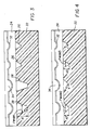
- FIG. 3 shows the depressions 28 and the wobble groove 26 in the recordable area 20.
- the depth d2 of the groove 26 is greater than 170 nm and can be in a range of 170 nm to 300 nm. By having this depth d2 it substantially contributes to improved performance during writing and read-out process.
- the depressions 28 which forms a wall angle a which has been found to preferably be in a range of 40-80°.
- the depressions 28 have a width FWHM1 which is measured at full width half maximum (FWHM). In other words, at one half the height of the depression 28.
- FWHM1 is in a range of 200 nm to 800 nm.
- FIG. 4 shows the wobble groove 26 in the read-only area 18 and recordable area 20.
- the wobble groove 26 in the recordable area 20 has a depth d3 in a range of 100 to 300 nm.
- the wobble grooves 26 in the read-only area 18 have a width FWHM2 in a range of 200 to 800 nm.
- the wobble grooves 26 in the read-only area 18 form a wall angle b in a range of 40-80°.
- the depth d3 of the wobble groove 26 in recordable area is a range of 100 to 300 nm.
- the wobble grooves 26 in the recordable area have a width FWHM3 in a range of 200 nm to 800 nm.
- the wobble grooves 26 in the recordable area form a wall angle c in a range of 40-80° .
- FIG. 5 shows the wobble groove 26 in the intrack position in the read-only area 18 depicting the relationship of the depressions 28.
- the depth dimensions are the same as described in FIG. 3 and 4 for the modulated groove and the groove.
- the length of each modulated segment of the groove is variable based on the 9 discreet lengths allowable in the Orange Book.
- FIG. 6 is view similar to FIG. 3 showing the depressions 28 relative to the recording layer 24 and the substrate 22.
- Various dimensions and relationships which define the dye conformality are shown. It will be understood that the shown dimensions and relationships for dye conformality are also applicable for wobble groove 26. The following are the various dimensions and relationships which are needed to achieve appropriate dye conformality particularly for forming the wobble groove 26 in the read-only area 18 when they have a depth greater than 170 nm. By following the relationships given below it has been found that important advantages can be achieved.
- the signal modulation for a phase contrast signal is maximized when the phase depth of the mark which forms the depth modulated portion of the groove is 1/4 wave as compared to the land between the marks. Since the light is reflected and passes through this structure twice, the total phase difference on reflection is 1/2 wave. Similarly it is known that the maximum push pull tracking error signal occurs when the phase depth is 1/8 wave. Further it has been shown that to meet the criteria for signal modulation required in the Orange Book the marks should have phase depth between than 1/8 waves and 3/8 waves and that the phase depth for push pull tracking signals within the range required by the Orange book requires an average phase depth between 1/16 and 3/16 wave (See US-A-5,316,814.
- the recording layer 24 is preferably a dye layer spin coated onto the substrate 22.
- the read-only area 18 and recordable area 20 are covered by such recording layer 24.
- the surface of the substrate 22 is cleaned in a manner well known in the art by depositing a dye compatible solvent onto the surface of the substrate 22 while the hybrid optical disc 10 is rotating. The solvent dissolves and removes the residual portion of the recording layer 24 on the surface of the substrate 22.
- the solvent should be carefully selected.
- the conformality of the recording layer 24 can be in a range of 40-70%.
- a suitable solvent examples include alcohols, hydrocarbon halides, cellosolves, and ketones.
- solvents examples of such solvents are 2,2,3,3-tetrafluoropropanol, tetrachloroethane, dichorlomethane, methyl cellosolve, ethyl cellosolve, 1-methyoxy-2-propanol, 4-hydroxy-4-methyl-2-pentanone.
- Preferred solvents are alcohol's since they have the least effect on the preferred polycarbonate substrates.
- the hybrid optical disc wherein the depressions have a width FWHM1 in a range of 200 nm to 800 nm.
- the hybrid optical disc wherein the recording layer includes a dye and is solvent coated onto the substrate surface so that it has a conformality of 40-70% to have an acceptable optical path length.
Landscapes
- Optical Record Carriers And Manufacture Thereof (AREA)
- Optical Recording Or Reproduction (AREA)
Abstract
Description
- The present invention relates to optical recording discs and more particularly to a hybrid disc having a read-only area (ROM) in which a depth modulated groove is formed and a write once recordable or rewritable area.
- Optical recording discs of the write-once or rewriteable type include a substrate having a recording layer. The substrate is formed by injection molding to include a wobbled groove on the surface of the substrate where the recording layer is formed. The groove defines recording channels on the disc for recording data and also provides for tracking of the disc while writing or reading data. The groove, which generates a frequency modulated signal after detection and processing, also contains addressing and other information that are necessary for the write and read processes. The groove is usually in accordance with Orange Book specifications. "Orange Book" is a specification published by Philips Corporation and Sony Corporation which defines key properties of recordable compact disc (CD-R) media and recording procedures.
- The recording layer, which can include an organic dye, is deposited on the substrate so as to completely cover the groove. The recording layer can be deposited by various techniques, including spin-coating, gravure, roller, flexographic, and vapor phase deposition. A reflective layer is then formed over the entire recording layer using similar techniques. The reflective layer can be, for example, gold, silver, or copper.
- Hybrid optical discs are those discs which have a read-only area in which a depth modulated groove is formed and a recordable area. Typically a wobble groove is provided in both areas. As set forth in US-A-5,696,758 specifies geometry of the wobbled depth modulated groove. The reason for this is that hybrid discs typically have to meet the Orange Book specifications, and it is difficult to achieve these standards with a wobbled depth modulated groove. Particular depths are specified to be in accordance with the Orange Book specifications.
- It is an object of this invention to provide a hybrid optical disc which provides improved readability by increasing the tracking signal produced from the wobble groove.
- This object is achieved in a hybrid optical recording disc having a substrate and a recording layer disposed over the substrate, the substrate having a read-only (ROM) area in which a groove is modulated by depressions in the substrate and a recordable area in which the groove from the read-only area extends into the substrate in the recordable area, the improvement comprising:
the groove in the read-only area forming wobbling tracks having a depth greater than 170 nm. - An advantage of the present invention is to provide a hybrid optical disc having substantially improved tracking signal. It has been discovered that the performance can be improved by forming the groove in the read-only area with a depth greater than 170 nm.
- Another advantage of the present invention is that the conformality of the recording layer on the substrate permits a greater depth of the depressions in the groove than has heretofore been possible while still meeting Orange Book specifications.
- An important feature of the present invention is that the bottoms of the groove in the read-only and recordable areas are rounded. This permits improved manufacturability of hybrid optical disc in accordance with this invention. It facilitates replication of optical discs either by injection molding or such other technique such as embossing..
- FIG. 1 is a top view of a hybrid optical disc in accordance with the present invention;
- FIG. 2 is an enlarged perspective of a portion of the hybrid optical disk of FIG. 1;
- FIGS. 3, 4 and 5 are cross-sectional views respectively taken along the lines 3-3, 4-4 and 5-5; and
- FIG. 6 shows a cross-sectional view of the
depression 28 and various dimensions which are needed to achieve desired conformality. -
- Referring to FIG. 1, a hybrid
optical disc 10 is shown in accordance with the present invention. The hybridoptical disc 10 has an innerperipheral edge 12, which defines acentral hole 14, and an outerperipheral edge 16. Thecentral hole 14 permits the hybridoptical disc 10 to be mounted in an optical disc transport device which can be used in either a reading or a writing mode. The hybridoptical disc 10 further includes a read-only area 18 and a recordable-area 20. Although it is only necessary to have a single read-only area 18 and a singlerecordable area 20 in the region near thecentral hole 14 there are a plurality of interspersedareas peripheral edge 16 there is only arecordable area 20. As will be well understood by those skilled in the art arecording layer 24 can contain a dye such as a pthalocyanine dye shown in FIGS. 3-5 is responsive to laser light that change its physical and or optical properties to permit write once recording. However, it will be understood that therecording layer 24 can be formed from a rewritable material such as magnetooptic material or phase change material and the present invention is not limited to write once dyes. - Referring now to FIG. 2, an enlarged perspective of the hybrid
optical disc 10 is shown of the read-only area 18 andrecordable area 20. In accordance with the present invention, asubstrate 22 which can be formed by injection molding includes awobble groove 26 in both the read-only area 18 and therecordable area 20 which provides tracking information when the hybridoptical disk 10 is either read from or written to . Thewobble groove 26 has a substantially V-shaped profile. As shown adepression 28 is formed in thewobble groove 26 in the read-only area 18. Aland 30 is provided between eachwobble groove 26. Thesubstrate 22 can be formed of an optically transparent polycarbonate as well understood to those skilled in the art. However, thesubstrate 22 could also be formed from other materials such as glass. - A preferred method of making the
substrate 22 is by injection molding. During the injection molding process, thesubstrate 22 is formed to define thewobble groove 26 and thedepressions 28 on the surface of thesubstrate 22. Over the surface of thesubstrate 22 is deposited therecording layer 24. In accordance with the present invention, thewobble groove 26 is continuous and extends throughout the read-only area 18 and therecordable area 20. Preferably, thewobble groove 26 is a continuous spiral. In any event thewobble groove 26 and the signals produced by thedepressions 28 conform to Orange Book specifications. - Turning now to FIG. 3 which shows the
depressions 28 and thewobble groove 26 in therecordable area 20. The depth d2 of thegroove 26 is greater than 170 nm and can be in a range of 170 nm to 300 nm. By having this depth d2 it substantially contributes to improved performance during writing and read-out process. In FIG. 3 is shown thedepressions 28 which forms a wall angle a which has been found to preferably be in a range of 40-80°. Thedepressions 28 have a width FWHM1 which is measured at full width half maximum (FWHM). In other words, at one half the height of thedepression 28. FWHM1 is in a range of 200 nm to 800 nm. - Turning now to FIG. 4 which shows the
wobble groove 26 in the read-only area 18 andrecordable area 20. Thewobble groove 26 in therecordable area 20 has a depth d3 in a range of 100 to 300 nm. Thewobble grooves 26 in the read-only area 18 have a width FWHM2 in a range of 200 to 800 nm. The wobble grooves 26 in the read-only area 18 form a wall angle b in a range of 40-80°. The depth d3 of thewobble groove 26 in recordable area is a range of 100 to 300 nm. Thewobble grooves 26 in the recordable area have a width FWHM3 in a range of 200 nm to 800 nm. The wobble grooves 26 in the recordable area form a wall angle c in a range of 40-80° . - Turning now to FIG. 5 which shows the
wobble groove 26 in the intrack position in the read-only area 18 depicting the relationship of thedepressions 28. The depth dimensions are the same as described in FIG. 3 and 4 for the modulated groove and the groove. The length of each modulated segment of the groove is variable based on the 9 discreet lengths allowable in the Orange Book. - FIG. 6 is view similar to FIG. 3 showing the
depressions 28 relative to therecording layer 24 and thesubstrate 22. Various dimensions and relationships which define the dye conformality are shown. It will be understood that the shown dimensions and relationships for dye conformality are also applicable forwobble groove 26. The following are the various dimensions and relationships which are needed to achieve appropriate dye conformality particularly for forming thewobble groove 26 in the read-only area 18 when they have a depth greater than 170 nm. By following the relationships given below it has been found that important advantages can be achieved. It should be noted that for thedepression 28 the term "d1" is the same as dg given below and when thewobble groove 26 is used in the read-only 18 the term "d2" is the same as dg given below and when thewobble groove 26 is used in therecordable area 20 the term "d3" is the same as dg given below. - td = thickness of dye layer on the land between the grooves
- tg = thickness of dye layer in the groove or depression
- dd = depth of the conformal depression in the dye layer over the groove
- dg = depth of the groove or depression
- npc = the real portion of the index of refraction of the substrate
- nd = the real portion of the index of refraction of the dye layer
- λ = the wavelength of the readout laser
-
- It is well known that the signal modulation for a phase contrast signal is maximized when the phase depth of the mark which forms the depth modulated portion of the groove is 1/4 wave as compared to the land between the marks. Since the light is reflected and passes through this structure twice, the total phase difference on reflection is 1/2 wave. Similarly it is known that the maximum push pull tracking error signal occurs when the phase depth is 1/8 wave. Further it has been shown that to meet the criteria for signal modulation required in the Orange Book the marks should have phase depth between than 1/8 waves and 3/8 waves and that the phase depth for push pull tracking signals within the range required by the Orange book requires an average phase depth between 1/16 and 3/16 wave (See US-A-5,316,814. The
recording layer 24 is preferably a dye layer spin coated onto thesubstrate 22. - During deposition of the
recording layer 24, the read-only area 18 andrecordable area 20 are covered bysuch recording layer 24. Thus, prior to deposition of areflective layer 32, the surface of thesubstrate 22 is cleaned in a manner well known in the art by depositing a dye compatible solvent onto the surface of thesubstrate 22 while the hybridoptical disc 10 is rotating. The solvent dissolves and removes the residual portion of therecording layer 24 on the surface of thesubstrate 22. - In order to improve the conformality of the
recording layer 24 on thesubstrate 22 the solvent should be carefully selected. By selecting the solvent, the conformality of therecording layer 24 can be in a range of 40-70%. For a specific example when using a phthalocyanine in a host material is solvent coated onto the surface of thesubstrate 22 using a suitable solvent. Examples of such a solvent are alcohols, hydrocarbon halides, cellosolves, and ketones. Examples of such solvents are 2,2,3,3-tetrafluoropropanol, tetrachloroethane, dichorlomethane, methyl cellosolve, ethyl cellosolve, 1-methyoxy-2-propanol, 4-hydroxy-4-methyl-2-pentanone. Preferred solvents are alcohol's since they have the least effect on the preferred polycarbonate substrates. - Other features of the invention are included below.
- The hybrid optical disc wherein the depressions form a wall angle a in a range of 40-80°.
- The hybrid optical disc wherein the depressions have a width FWHM1 in a range of 200 nm to 800 nm.
- The hybrid optical disc wherein the recording layer includes a dye and is solvent coated onto the substrate surface so that it has a conformality of 40-70% to have an acceptable optical path length.
-
- 10
- hybrid optical disc
- 12
- inner peripheral edge
- 14
- central hole
- 16
- outer peripheral edge
- 18
- read-only area
- 20
- recordable-area
- 22
- substrate
- 24
- recording layer
- 26
- wobble groove
- 28
- depression
- 30
- land
- 32
- reflective layer
Claims (10)
- A hybrid optical recording disc having a substrate and a recording layer disposed over the substrate, the substrate having a read-only (ROM) area in which a groove is modulated by depressions in the substrate and a recordable area in which the groove from the read-only area extends into the substrate in the recordable area, the improvement comprising:
the groove in the read-only area forming wobbling tracks having a depth greater than 170 nm. - The hybrid optical disc according to claim 1 wherein the groove in the recordable area has a different wobble amplitude than the groove in the read-only area.
- The hybrid optical disc according to claim 2 wherein the depth d2 of the depression in the groove in the read-only area is in a range substantially greater than 170 nm and less than 300 nm.
- The hybrid optical disc according to claim 1 wherein the grooves in the read-only area form a wall angle b in a range of 40-80° .
- The hybrid optical disc according to claim 4 wherein the grooves in the recordable area form a wall angle c in a range of 40-80°.
- The hybrid optical disc according to claim 2 wherein the grooves in the read-only area have a width FWHM2 in a range of 200 nm to 800 nm.
- The hybrid optical disc according to claim 6 wherein the grooves in the recordable area have a width FWHM3 in a range of 200 nm to 800 nm.
- The hybrid optical disc according to claim 1 wherein the recording layer includes a dye responsive to laser light at a predetermined frequency and intensity to change its physical structure.
- The hybrid optical disc according to claim 1 wherein the depth d3 of the groove in recordable area is a range of 100 to 300 nm.
- A hybrid optical recording disc having a substrate and a recording layer disposed over the substrate, the substrate having a recordable area which includes a wobbled groove and a read-only (ROM) area in which a groove is modulated by depressions in the substrate, the improvement comprising:
the groove in the read-only area forming wobbling tracks having a depth such that the difference in optical phase depth at the groove between two depressions and the optical phase depth at the land between the grooves is greater than 1/16 λ and less than 3/16 λ, λ being the wavelength of the readout light.
Applications Claiming Priority (2)
| Application Number | Priority Date | Filing Date | Title |
|---|---|---|---|
| US09/323,496 US6212158B1 (en) | 1999-06-01 | 1999-06-01 | Hybrid optical disc construction |
| US323496 | 1999-06-01 |
Publications (2)
| Publication Number | Publication Date |
|---|---|
| EP1058242A2 true EP1058242A2 (en) | 2000-12-06 |
| EP1058242A3 EP1058242A3 (en) | 2002-05-15 |
Family
ID=23259444
Family Applications (1)
| Application Number | Title | Priority Date | Filing Date |
|---|---|---|---|
| EP00201796A Ceased EP1058242A3 (en) | 1999-06-01 | 2000-05-22 | Hybrid optical disc |
Country Status (5)
| Country | Link |
|---|---|
| US (2) | US6212158B1 (en) |
| EP (1) | EP1058242A3 (en) |
| JP (1) | JP2000348379A (en) |
| KR (1) | KR20010007128A (en) |
| TW (1) | TW499676B (en) |
Cited By (2)
| Publication number | Priority date | Publication date | Assignee | Title |
|---|---|---|---|---|
| EP1296318A1 (en) * | 2001-09-10 | 2003-03-26 | Ricoh Company, Ltd. | Optical information recording medium and information recording method using the recording medium |
| EP1321929A3 (en) * | 2001-12-20 | 2003-11-12 | Eastman Kodak Company | Hybrid disc architecture |
Families Citing this family (48)
| Publication number | Priority date | Publication date | Assignee | Title |
|---|---|---|---|---|
| TW476958B (en) * | 1999-02-09 | 2002-02-21 | Ricoh Kk | Optical disk and method of producing the same |
| WO2000072319A1 (en) * | 1999-05-19 | 2000-11-30 | Fujitsu Limited | Information recording medium and manufacturing method thereof |
| KR100379411B1 (en) * | 1999-06-28 | 2003-04-10 | 엘지전자 주식회사 | biochip and method for patterning and measuring biomaterial of the same |
| KR100339379B1 (en) * | 1999-10-29 | 2002-06-03 | 구자홍 | biochip and apparatus and method for measuring biomaterial of the same |
| JP3865547B2 (en) * | 1999-11-12 | 2007-01-10 | 株式会社リコー | Optical recording medium and method for manufacturing optical recording medium |
| JP2001184726A (en) * | 1999-12-24 | 2001-07-06 | Sony Corp | Optical recording medium substrate, optical recording medium, method of manufacturing optical recording medium, and method of optical recording / reproducing |
| JP2001357534A (en) * | 2000-04-10 | 2001-12-26 | Victor Co Of Japan Ltd | Information recording medium |
| US7054260B2 (en) * | 2000-04-26 | 2006-05-30 | Optical Disc Corporation | Hybrid discs |
| US6570840B1 (en) | 2000-04-26 | 2003-05-27 | Optical Disc Corporation | Figure of merit in optical recording structures |
| US7016295B2 (en) | 2000-04-26 | 2006-03-21 | Optical Disc Corporation | Hybrid discs displaying certain dimensional values |
| US7061594B2 (en) * | 2000-11-09 | 2006-06-13 | Burstein Technologies, Inc. | Disc drive system and methods for use with bio-discs |
| AU2002241851A1 (en) * | 2001-01-11 | 2002-07-24 | Burstein Technologies, Inc. | Optical disc analysis system including related methods for biological and medical imaging |
| US6982110B2 (en) * | 2001-05-25 | 2006-01-03 | Ricoh Company, Ltd. | Information recording medium and manufacturing method thereof |
| KR100750099B1 (en) * | 2001-05-30 | 2007-08-17 | 삼성전자주식회사 | Recordable optical discs on land and groove tracks |
| TW567478B (en) * | 2001-06-15 | 2003-12-21 | Ritek Corp | Hybrid disc recording medium |
| US7221632B2 (en) * | 2001-07-12 | 2007-05-22 | Burstein Technologies, Inc. | Optical disc system and related detecting methods for analysis of microscopic structures |
| JP4300727B2 (en) * | 2001-10-09 | 2009-07-22 | ソニー株式会社 | DISC RECORDING MEDIUM, DISC DRIVE DEVICE, REPRODUCTION METHOD, AND DISC MANUFACTURING METHOD |
| JP4652641B2 (en) * | 2001-10-11 | 2011-03-16 | ソニー株式会社 | Disc recording medium, disc drive apparatus, and playback method |
| SK1782004A3 (en) | 2001-10-15 | 2004-09-08 | Koninkl Philips Electronics Nv | Record carrier and apparatus for scanning the record carrier |
| US7280461B2 (en) | 2001-10-16 | 2007-10-09 | Sony Corporation | Optical recording/reproducing medium, stamper for manufacturing optical recording/reproducing medium, and optical recording/reproducing apparatus |
| US20080094974A1 (en) * | 2001-11-09 | 2008-04-24 | Burstein Technologies, Inc. | Optical disc system and related detecting methods for analysis of microscopic structures |
| MXPA04003991A (en) * | 2002-02-07 | 2005-01-25 | Verification Technologies Inc | Method and system for optical disc copy-protection. |
| US7406022B2 (en) * | 2002-03-15 | 2008-07-29 | Samsung Electronics Co., Ltd. | Optical recording medium |
| US20040081069A1 (en) * | 2002-10-17 | 2004-04-29 | Hitachi Maxell, Ltd. | Optical information-recording medium and method for producing the same |
| AU2002354490A1 (en) * | 2002-12-13 | 2004-07-09 | Fujitsu Limited | Magneto-optical recording medium and magneto-optical storage apparatus |
| US20040179462A1 (en) * | 2003-03-10 | 2004-09-16 | National Film Laboratories, Inc. Dba Crest National | Optical disc having increased storage capacity |
| DE602004027907D1 (en) * | 2003-05-30 | 2010-08-12 | Doug Carson & Associates Inc | IMPROVED FORMAT FOR MULTILAYER OPTICAL DATA CARRIER |
| US20050005137A1 (en) * | 2003-06-16 | 2005-01-06 | Microsoft Corporation | System and method for individualizing installation media |
| US7086073B2 (en) * | 2003-06-16 | 2006-08-01 | Microsoft Corporation | Optical storage media with embedded security device |
| US7895449B2 (en) * | 2003-06-16 | 2011-02-22 | Microsoft Corporation | System and method for securely delivering installation keys to a production facility |
| US20070220537A1 (en) * | 2003-06-16 | 2007-09-20 | Microsoft Corporation | Counterfeit-resistant portable storage media with embedded security device |
| US20050018574A1 (en) * | 2003-07-25 | 2005-01-27 | Jenkins Jens C. | Hybrid optical storage media and methods of use |
| JP2008520057A (en) * | 2004-11-11 | 2008-06-12 | ソフト−アール・リサーチ・エルエルシー | Optical recording disk and method for recording data on an optical recording disk |
| US8151366B2 (en) * | 2004-11-12 | 2012-04-03 | Cinram International Inc. | Secure optical media storage |
| US20070020560A1 (en) * | 2005-05-27 | 2007-01-25 | Larson Lief C | Limited play optical discs |
| US7564771B2 (en) * | 2005-07-14 | 2009-07-21 | Cinram International Inc. | Bonded pre-recorded and pre-grooved optical disc |
| US7684309B2 (en) * | 2005-11-03 | 2010-03-23 | Cinram International Inc. | Multi-purpose high-density optical disc |
| US7986611B1 (en) | 2007-03-22 | 2011-07-26 | Cinram International Inc. | High-density optical recording media and method for making same |
| US8675464B2 (en) * | 2005-11-03 | 2014-03-18 | Cinram Group, Inc. | Dual sided optical storage media and method for making same |
| EP1952399A2 (en) * | 2005-11-14 | 2008-08-06 | Koninklijke Philips Electronics N.V. | Hybrid optical disc |
| JP4533854B2 (en) * | 2006-03-06 | 2010-09-01 | 株式会社東芝 | Magnetic recording / reproducing apparatus, magnetic recording method, and magnetic recording / reproducing method |
| US7910191B1 (en) | 2006-03-09 | 2011-03-22 | Cinram International Inc. | Method for forming light-transmitting cover layer for optical recording medium |
| US20110096655A1 (en) * | 2006-03-09 | 2011-04-28 | Cinram International Inc. | Forming light-transmitting cover layer for recording medium |
| US20090075015A1 (en) * | 2007-07-24 | 2009-03-19 | Detty Michael R | Limited Play Optical Discs |
| US9019807B2 (en) | 2008-02-19 | 2015-04-28 | Thomson Licensing | Optical disc with pre-recorded and recordable regions and method of forming the disc |
| WO2009105215A2 (en) * | 2008-02-19 | 2009-08-27 | Thomson Licensing | Optical disc with pre-recorded and recordable regions and method of forming the disc |
| US8739299B1 (en) | 2009-12-24 | 2014-05-27 | Cinram Group, Inc. | Content unlocking |
| US9056422B2 (en) * | 2013-04-09 | 2015-06-16 | Massachusetts Institute Of Technology | Methods and apparatus for encoded textures |
Family Cites Families (11)
| Publication number | Priority date | Publication date | Assignee | Title |
|---|---|---|---|---|
| DE68921453T2 (en) * | 1988-12-28 | 1995-07-13 | Canon Kk | Information recording media. |
| US5191563A (en) * | 1989-06-29 | 1993-03-02 | Digital Equipment Corporation | Method for increasing track density of magneto-optical storage media |
| US5138598A (en) * | 1990-01-25 | 1992-08-11 | Sony Corporation | Optical disk having relatively wide ram tracks and relatively narrow rom tracks |
| US5204852A (en) * | 1990-02-17 | 1993-04-20 | Victor Company Of Japan, Ltd. | Optical disc-like recoding medium and manufacturing method thereof |
| US5316814A (en) | 1991-05-14 | 1994-05-31 | Ricoh Company, Ltd. | Optical information recording medium |
| JP2879185B2 (en) * | 1993-04-16 | 1999-04-05 | ティーディーケイ株式会社 | Magneto-optical disk |
| JP2697555B2 (en) * | 1993-05-26 | 1998-01-14 | 松下電器産業株式会社 | Optical information recording medium |
| JP3652017B2 (en) | 1995-08-23 | 2005-05-25 | 三井化学株式会社 | Optical recording medium |
| JP3065529B2 (en) * | 1996-03-12 | 2000-07-17 | 株式会社リコー | Optical information recording medium and tracking servo method for optical information recording medium |
| JP3201289B2 (en) * | 1996-11-12 | 2001-08-20 | 日本ビクター株式会社 | optical disk |
| JP3831063B2 (en) * | 1997-04-25 | 2006-10-11 | パイオニア株式会社 | Optical disc discrimination device |
-
1999
- 1999-06-01 US US09/323,496 patent/US6212158B1/en not_active Expired - Lifetime
-
2000
- 2000-04-07 TW TW089106419A patent/TW499676B/en not_active IP Right Cessation
- 2000-05-22 EP EP00201796A patent/EP1058242A3/en not_active Ceased
- 2000-05-23 JP JP2000150999A patent/JP2000348379A/en active Pending
- 2000-05-29 KR KR1020000028931A patent/KR20010007128A/en not_active Ceased
- 2000-12-18 US US09/739,953 patent/US6480462B2/en not_active Expired - Fee Related
Non-Patent Citations (1)
| Title |
|---|
| None * |
Cited By (3)
| Publication number | Priority date | Publication date | Assignee | Title |
|---|---|---|---|---|
| EP1296318A1 (en) * | 2001-09-10 | 2003-03-26 | Ricoh Company, Ltd. | Optical information recording medium and information recording method using the recording medium |
| US7236448B2 (en) | 2001-09-10 | 2007-06-26 | Ricoh Company, Ltd. | Optical information recording medium and information recording method using the recording medium |
| EP1321929A3 (en) * | 2001-12-20 | 2003-11-12 | Eastman Kodak Company | Hybrid disc architecture |
Also Published As
| Publication number | Publication date |
|---|---|
| US6212158B1 (en) | 2001-04-03 |
| JP2000348379A (en) | 2000-12-15 |
| EP1058242A3 (en) | 2002-05-15 |
| KR20010007128A (en) | 2001-01-26 |
| US6480462B2 (en) | 2002-11-12 |
| US20010005357A1 (en) | 2001-06-28 |
| TW499676B (en) | 2002-08-21 |
Similar Documents
| Publication | Publication Date | Title |
|---|---|---|
| US6212158B1 (en) | Hybrid optical disc construction | |
| US5726970A (en) | Multi-layer optical recording medium | |
| EP0376678B1 (en) | Information recording medium | |
| KR100455078B1 (en) | Optical recording medium | |
| US6128271A (en) | Optical recording medium | |
| KR100551145B1 (en) | Optical disc | |
| KR100888179B1 (en) | Optical disk and method for manufacturing the same | |
| CA2070221A1 (en) | Optical recording medium | |
| EP1256946A1 (en) | Optical information recording medium | |
| KR20040094896A (en) | Optical data storage medium and use of such medium | |
| WO1999013462A1 (en) | Updatable optical data storage disc having reduced crosstalk between tracks, and drive for same | |
| US6721265B1 (en) | High-density optical information recording medium and a substrate and a stamper for the manufacture thereof | |
| US5554451A (en) | Optical data recording medium | |
| JP3499406B2 (en) | optical disk | |
| US20050068883A1 (en) | Optical recording medium and method for production of optical recording medium | |
| US5206063A (en) | Optical recording element with rom and recording regions | |
| KR100236569B1 (en) | Information recording medium and its recording and reproducing method | |
| KR100596894B1 (en) | Optical information medium and recording method thereof | |
| US6620480B1 (en) | Pre-engraved substrate for magnetic, magneto-optical, or phase transition optical disc | |
| JPH02185737A (en) | Optical recording medium disk | |
| JPH0512680A (en) | Optical information recording medium and stamper master manufacturing method for optical information recording medium | |
| JP2848992B2 (en) | Optical recording medium and substrate for optical recording medium used therefor | |
| JPH0573955A (en) | Optical recording medium disc | |
| JP2751868B2 (en) | Optical recording medium and recording / reproducing method thereof | |
| JPH0337841A (en) | optical disk |
Legal Events
| Date | Code | Title | Description |
|---|---|---|---|
| PUAI | Public reference made under article 153(3) epc to a published international application that has entered the european phase |
Free format text: ORIGINAL CODE: 0009012 |
|
| AK | Designated contracting states |
Kind code of ref document: A2 Designated state(s): AT BE CH CY DE DK ES FI FR GB GR IE IT LI LU MC NL PT SE |
|
| AX | Request for extension of the european patent |
Free format text: AL;LT;LV;MK;RO;SI |
|
| PUAL | Search report despatched |
Free format text: ORIGINAL CODE: 0009013 |
|
| AK | Designated contracting states |
Kind code of ref document: A3 Designated state(s): AT BE CH CY DE DK ES FI FR GB GR IE IT LI LU MC NL PT SE |
|
| AX | Request for extension of the european patent |
Free format text: AL;LT;LV;MK;RO;SI |
|
| 17P | Request for examination filed |
Effective date: 20021021 |
|
| AKX | Designation fees paid |
Designated state(s): DE FR GB |
|
| 17Q | First examination report despatched |
Effective date: 20050209 |
|
| STAA | Information on the status of an ep patent application or granted ep patent |
Free format text: STATUS: THE APPLICATION HAS BEEN REFUSED |
|
| 18R | Application refused |
Effective date: 20070302 |