The present invention relates to image processing
apparatuses, image processing methods, noise-amount estimate
apparatuses, noise-amount estimate methods, and storage
media, and more particularly, to an image processing
apparatus, an image processing method, a noise-amount
estimate apparatus, a noise-amount estimate method, and a
storage medium which allow noise included in data, such as a
motion image, to be removed more effectively.
In general, data such as transmitted or reproduced
image data and sound data includes noise which changes as
time elapses. To remove the noise included in the data,
there have been known methods in which the average, namely,
the whole average, of the whole input data is obtained and
in which the average of a part of the input data, which is
called a moving average, is obtained.
The method in which the whole average is calculated is
effective when the degree of noise included in data, namely,
the signal-to-noise ratio (S/N ratio) of the data, is
uniform. When the S/N ratio of data varies, however, a
portion of the data having a low S/N ratio affects a portion
of the data having a high S/N ratio to make it difficult to
remove the noise effectively in some cases.
In the method in which the moving average is calculated,
since the average of data positioned close to the current
input data in the time domain is obtained, the processing
result is affected by a change in the S/N ratio of the data.
In other words, the processing result has a high S/N ratio
for a portion of the data having a high S/N ratio, but the
processing result has a low S/N ratio for a portion of the
data having a low S/N ratio.
When noise is removed from the data of a motion image,
it may be difficult to remove the noise effectively due to
movement even if the whole average or the moving average is
obtained at a pixel disposed at the same position in each
frame.
Accordingly, it is an object of the present invention
to address the foregoing drawbacks.
The foregoing object is achieved in one aspect of the
present invention through the provision of an image
processing apparatus for processing input pixel data and for
outputting the processed input pixel data as output pixel
data, including input reliability calculation means for
calculating an input reliability indicating the reliability
of the input pixel data; output reliability calculation
means for calculating an output reliability indicating the
reliability of the output pixel data; motion-amount
detecting means for detecting the motion amount of the input
pixel data; compensation means for compensating the output
reliability according to the motion amount; and processing
means for processing the input pixel data according o the
input reliability and the compensated output reliability,
and for outputting the output pixel data.
The foregoing object is achieved in another aspect of
the present invention through the provision of a noise-amount
estimate apparatus for estimating the amount of noise
included in pixel data, including variance calculation means
for processing in units of a predetermined number of pixels
and for calculating the variance of a plurality of pixel
data in a local area including each pixel data; histogram
generating means for generating the histogram of the
variance calculated for each pixel data, in units of the
predetermined number of pixels; and noise-amount calculation
means for obtaining the amount of noise included in the
pixel data according to the histogram, in units of the
predetermined number of pixels.
The foregoing object is achieved in still another
aspect of the present invention through the provision of an
image processing method for processing input pixel data and
for outputting the processed input pixel data as output
pixel data, including a step of calculating an input
reliability indicating the reliability of the input pixel
data; a step of calculating an output reliability indicating
the reliability of the output pixel data; a step of
detecting the motion amount of the input pixel data; a step
of compensating the output reliability according to the
motion amount; and a step of processing the input pixel data
according to the input reliability and the compensated
output reliability, and of outputting the output pixel data.
The foregoing object is achieved in yet another aspect
of the present invention through the provision of a noise-amount
estimate method for estimating the amount of noise
included in pixel data, including a step of processing in
units of a predetermined number of pixels and of calculating
the variance of a plurality of pixel data in a local area
including each pixel data; a step of generating the
histogram of the variance calculated for each pixel data, in
units of the predetermined number of pixels; and a step of
obtaining the amount of noise included in the pixel data
according to the histogram, in units of the predetermined
number of pixels.
The foregoing object is achieved in yet still another
aspect of the present invention through the provision of a
storage medium for storing a computer-controllable program
for processing input pixel data and for outputting the
processed input pixel data as output pixel data, the program
including a step of calculating an input reliability
indicating the reliability of the input pixel data; a step
of calculating an output reliability indicating the
reliability of the output pixel data; a step of detecting
the motion amount of the input pixel data; a step of
compensating the output reliability according to the motion
amount; and a step of processing the input pixel data
according to the input reliability and the compensated
output reliability, and of outputting the output pixel data.
The foregoing object is achieved in a further aspect of
the present invention through the provision of a storage
medium for storing a computer-controllable program for
estimating the amount of noise included in pixel data, the
program including a step of processing in units of
predetermined number of pixels and of calculating the
variance of a plurality of pixel data in a local area
including each pixel data; a step of generating the
histogram of the variance calculated for each pixel data, in
units of the predetermined number of pixels; and a step of
obtaining the amount of noise included in the pixel data
according to the histogram, in units of the predetermined
number of pixels.
Embodiments of the invention will now be described, by
way of example only, with reference to the accompanying
drawings in which:
Fig. 1 is a block diagram of an noise reduction (NR)
processing circuit according to an example embodiment of
the present invention.
Fig. 2A is a view showing the input data to be
processed by the NR processing circuit shown in Fig. 1.
Fig. 2B is a view showing the reliability of the input
data to be processed by the NR processing circuit shown in
Fig. 1.
Fig. 3 is a block diagram showing an example structure
of the NR processing circuit shown in Fig. 1.
Fig. 4 is a block diagram showing an example structure
of a noise-amount calculation section 11 shown in Fig. 3.
Fig. 5 is a view showing the processing of the noise-amount
calculation section 11 shown in Fig. 4.
Fig. 6 is a block diagram showing an example structure
of an output reliability calculation section 13 shown in Fig.
3.
Fig. 7A is a view showing the processing of input data
in the NR processing circuit shown in Fig. 3.
Fig. 7B is a view showing the processing of output data
in the NR processing circuit shown in Fig. 3.
Fig. 8 is a flowchart showing the processing of the NR
processing circuit shown in Fig. 3.
Fig. 9 is a view showing an input-reliability
calculation method.
Fig. 10 is a block diagram of a first example structure
of the NR processing circuit shown in Fig. 1.
Fig. 11A is a view showing a pixel area used for
calculating the amount of motion in a motion-amount
calculation section 16 shown in Fig. 10.
Fig. 11B is a view showing a conversion function for
converting a difference calculated in the pixel area shown
in Fig. 11A to the amount of motion.
Fig. 12 is a block diagram showing an example structure
of an output reliability calculation section 13 shown in Fig.
10.
Fig. 13 is a view showing noise-amount estimate
processing. In Fig. 13, (A) shows an image without noise,
(B) shows the image of noise which changes in frames but is
constant spatially, (C) shows an image having noise
generated by adding the image shown in (A) to that shown in
(B), and (D) shows the estimated noise amount of the image
having noise shown in (C).
Fig. 14 is a view showing the amount of noise.
Fig. 15A is a view showing the calculation of a
variance in a local area of an image, the variance being
used for estimating the amount of noise.
Fig. 15B is a view showing a noise-amount estimate
method in which the variance having the most frequent value
in a variance histogram is regarded as the amount of noise.
Fig. 16 is a block diagram showing another example
structure of a noise-amount estimate section 1 shown in Fig.
10.
Fig. 17 is a flowchart of noise-amount estimate
processing executed by the noise-amount estimate section 1
shown in Fig. 16.
Fig. 18 is a chart showing the histograms of the
amounts of noise in the original image, a noise image, and
an input image.
Fig. 19 is a chart showing the result of simulation for
estimating the amount of noise in an example embodiment of
the present invention.
Fig. 20A is a view showing a computer into which a
program for executing processing related to an example
embodiment of the present invention is installed.
Fig. 20B is a view showing example storage media for
storing the program which executes the processing related to
an example embodiment of the present invention.
Fig. 20C is a view showing cases in which the program
for executing the processing related to an example
embodiment of the present invention is distributed to the
computer through a satellite and a network.
Fig. 21 is a block diagram of a computer into which the
program for executing the processing related to an example
embodiment of the present invention is installed.
Fig. 1 shows an example structure of a noise reduction
(NR) processing circuit 100 according to an example
embodiment of the present invention.
This NR processing circuit 100 is formed of a noise-amount
estimate section 1 and a noise removing section 2.
The noise-amount estimate section 1 estimates the amount of
noise included in input data, and the noise removing section
2 applies processing to the input data according to the
amount of noise. The NR processing circuit 100 effectively
removes noise from the input data and outputs data.
Specifically, for example, to simplify a description, a
case is examined in which input data having a constant true
value and on which noise fluctuating in time is superposed,
as shown in Fig. 2A, is averaged to remove the noise
fluctuating in time. The noise is effectively removed by
setting a weight for input data having a large noise level,
namely, having a low S/N ratio, to a small value and by
setting a weight for input data having a small noise level,
namely,-having a high S/N ratio, to a large value.
In the NR processing circuit 100 shown in Fig. 1, as
the evaluation value of input data, the degree of
reliability indicating how the input data is close to the
true value, which is the reliability of the input data
against the true value, for example, shown in Fig. 2B, is
obtained. The NR processing circuit 100 calculates its
average while the weight corresponding to the reliability is
applied to the input data, to effectively remove the noise.
Therefore, the
NR processing circuit 100 shown in Fig.
1 obtains a weighted average of the input data by the use of
the weight corresponding to its reliability and outputs it
as output data. The output data y(t) is obtained from the
following expression, where x(t), y(t), and α
x(t) indicate the
input data, the output data, and the reliability of the
input data at the time "t," respectively.
It is assumed here that a larger weight is given to the
higher degree of reliability α
x(t) of input data.
The output data y(t-1), obtained one sample before the
current time "t," is calculated as follows from the
expression (1).
As for the output data y(t), the degree of reliability
α
y(t) indicating how the output data y(t) is close to the true
value, which is the reliability of the output data y(t)
against the true value, is introduced as an evaluation value
of the output data y(t). The reliability α
y(t-1) of the output
data y(t-1), obtained one sample before the current time
"t," is defined by the following expression.
According to the expression (3), the reliability αy(t-1)
of the output data y(t-1) is the sum of the reliability αx(i)
of the input data x(i) (i = 0, 1, 2, ..., t-1) processed so
far. Therefore, the reliability αy(t-1) of the output data
y(t-1) is large when input data close to the true value has
been input so far in many cases, and the reliability is
small when input data close to the true value has been input
so far in a few cases. In other words, the reliability αy(t-1)
of the output data y(t-1) reflects the closeness
(reliability) of the input data which has been input so far
to the true value. When input data which has been input so
far is close to the true value, it means that the output
data y(t-1) is also close to the true value. Conversely,
when input data which has been input so far is distant from
the true value, it means that the output value y(t-1) is
also distant from the true value. Therefore, the
reliability αy(t-1) expressed by the expression (3) represents
the closeness of the output data y(t-1) to the true value.
The output data y(t) and its reliability α
y(t) are
expressed as follows with the use of the expressions (1) to
(3).
α y ( t ) = α y ( t -1) + α x ( t ) The weight used to obtain the output data y(t) at the
time "t" is indicated by w(t), and defined by the following
expression.
w(t) = αy(t-1) / (αy(t-1) + αx(t))
From the expression (6), the following expression is
satisfied.
1 - w(t) = αx(t) /(αy(t-1) + αx(t) )
With the use of the expressions (6) and (7), the output
data y(t) in the expression (4) can be expressed in the
following way by a weighted average obtained by
multiplications and an addition.
y(t) = w(t)y(t-1) + (1 - w(t))x(t)
The weights w(t) and 1 - w(t) used in the expression
(8) can be obtained from the expression (6) with the use of
the reliability αy(t-1) of the output data y(t-1) obtained one
sample before and the reliability αx(t) of the current input
data x(t). The reliability αy(t) of the current output data
y(t) in the expression (5) can also be obtained with the use
of the reliability αy(t-1) of the output data y(t-1) obtained
one sample before and the reliability αx(t) of the current
input data x(t).
The reliability αx(t) of input data x(t) shown in Fig. 2B
is the reciprocal of the variance of input data in the
vicinity thereof. When the reliability αx(t) of the input
data x(t) and the reliability αy(t) of the output data y(t)
are expressed, respectively, by the reciprocals of the
corresponding variances σx(t) 2 or σy(t) 2, in other words, when
the reliability αx(t) and the reliability αy(t) are set as
follows,
αx(t) = 1/σx(t) 2 αy(t) = 1/σy(t) 2
the weight w(t) in the expression (8) can be obtained by the
following expression.
w(t) = σx(t) 2/(σy(t-1) 2 + σx(t) 2)
In this case, 1 - w(t) in the expression (8) can be
obtained by the following expression.
1 - w(t) = σy(t-1) 2/(σy(t-1) 2 + σx(t) 2)
A term, σy(t) 2, can be obtained by the following
expression.
σy(t) 2 = w(t)2σy(t-1) 2 + (1-w(t))2σx(t) 2
It is clear from the expression (4) that the expression
(8) obtained from the expressions (4) and (5) shows that the
input data x(t) is weighted by the weight corresponding to
the reliability αx(t) thereof, the output data y(t-1) obtained
one sample before is also weighted by the weight
corresponding to the reliability αy(t-1) thereof, the weighted
input data and the weighted output data are added, and the
sum is used as the output data y(t), which is the data
obtained by removing noise from the input data x(t).
The reliability αx(t) corresponding to the weight for the
input data x(t) indicates the closeness of the input data
x(t) against the true value, and the reliability αy(t-1)
corresponding to the weight for the output data y(t-1)
obtained one sample before indicates the closeness of the
output data y(t-1) against the true value. Since the true
value is constant in the present embodiment, when the output
data y(t) is obtained by the expression (8), which executes
an addition with whichever of the input data x(t) and the
output data y(t-1) closer to the true value being considered
more important, the output data y(t) is closer to the true
value.
In other words, a small weight is applied to input data
having a small reliability, which has been input, a large
weight is applied to that having a large reliability, and
the input data weighted in such a way is summed to obtain
the output data y(t) by the expression (8) (equivalent to
the expression (1)) led from the expression (1). More
intuitively, the output data y(t) is obtained by adding
input data such that input data having much noise do not
affect much and input data having little noise affects much.
Therefore, when the whole average is obtained, both
input data having a low s/n ratio and input data having a
high s/n ratio affect output data at the same level.
According to the expression (8), however, in the present
embodiment, input data having a low s/n ratio affects output
data little, and input data having a high s/n ratio affects
the output data much. As a result, the output data with
noise being more effectively removed than in a case the
whole average is used is obtained.
When the moving average is obtained, input data distant
in time do not affect output data at all even if it has a
high s/n ratio, and input data close in time affects the
output data much even if it has a low s/n ratio. According
to the expression (8), however, in the present embodiment,
input data affects the output data according to its s/n
ratio irrespective of the closeness in time. As a result,
the output data with noise being more effectively removed
than in a case when the moving average is used is obtained.
As described above, according to the expression (8),
the output data becomes closer to the true value by the
effect of input data having a high reliability (close to the
true value). Therefore, as input data having a high
reliability is processed in many cases, the output data
approaches the true value. As a result, the S/N ratio of
the output data is improved as time elapses.
In the above embodiment, it is assumed that the true
value is constant. For data with the true value being
changed, it is necessary, for example, to divide the data
into zones in which it is considered that the true value is
constant, and to apply the processing to each zone.
In the above embodiment, the variance of some input
data items disposed in the vicinity in time is used as the
reliability (hereinafter called input reliability) of the
input data. In this case, input reliability, output data,
or the reliability (hereinafter called output reliability)
of the output data cannot be obtained until the some input
data items are input. Until input data items used for
obtaining input reliability are input, it is possible, for
example, that input reliability or output reliability is not
calculated, and the simple average of input data which has
been input so far is obtained and used as the output data.
A method used until input data items used for obtaining
input reliability are input is not limited to the above one.
Fig. 3 shows a detailed example structure of the NR
processing circuit 100 shown in Fig. 1, which removes the
noise of input data in the foregoing way.
A latch circuit 111 receives input data. The latch
circuit 111 latches the input data, for example, in
synchronization with the timing when the input data is
received, and sends it to a subsequent-stage latch circuit
112 and to an noise-amount calculation section 11. The latch
circuit 112 and a latch circuit 113 latch the data output
from the previous- stage latch circuits 111 and 112, and send
it to the subsequent- stage latch circuits 113 and 114,
respectively, and to the noise-amount calculation section 11,
in the same way as the latch circuit 111. The latch circuit
114 latches the data output from the previous-stage latch
circuit 113 and sends it to the noise-amount calculation
section 11.
The noise-amount calculation section 11 receives the
same input data as that sent to the latch circuit 111 in
addition to the input data latched by the latch circuits 111
to 114. Therefore, when input data x(t) is sent to the latch
circuit 111 and to the noise-amount calculation section 11,
the noise-amount calculation section 11 also receives input
data x(t-1) to x(t-4) latched by the latch circuits 111 to
114. The input reliability calculation circuit 12 calculates,
for example, the variance of input data from the input data
x(t) to x(t-4), and sends the variance as the noise amount
of the input data x(t) to an input reliability calculation
section 12.
The noise-amount calculation section 11 and the latch
circuits 111 to 114 correspond to the noise-amount estimate
section 1 shown in Fig. 1.
The input reliability calculation section 12 calculates
the input reliability αx(t) of the input x(t) according to the
noise amount sent from the noise-amount calculation section
11, and sends it to an output reliability calculation
section 13 and to an weight calculation section 15.
Specifically, the input reliability calculation section 12
obtains the reciprocal of the variance serving as the noise
amount sent from the noise-amount calculation section 11,
and outputs it as the input reliability αx(t).
The output reliability calculation section 13 obtains
the output reliability αy(t) according to the expression (5)
with the use of the input reliability αx(t) sent from the
input reliability calculation section 12 and the output of a
latch circuit 14, and outputs it to the latch circuit 14.
The latch circuit 14 latches the output reliability αy(t)
sent from the output reliability calculation section 13, for
example, in synchronization with latching of the input data
x(t), and sends it to the output reliability calculation
section 13 and the weight calculation section 15. Therefore,
the latch circuit 14 sends the output reliability αy(t-1)
obtained one sample before, to the output reliability
calculation section 13 and the weight calculation section 15.
The weight calculation section 15 obtains a weight w(t)
according to the expression (6) with the use of the input
reliability αx(t) sent from the input reliability calculation
section 12 and the output reliability αy(t-1) sent from the
latch circuit 14, and sends it to a weighting section 21 and
an operation section 22.
The weighting section 21 multiplies the weight w(t)
sent from the weight calculation section 15 by the output of
a latch circuit 25, and sends the product to an operation
section 24. The operation section 22 subtracts the weight
w(t) sent from the weight calculation section 15, from one,
and sends the subtraction result, 1 - w(t), to a weighting
section 23. The weighting section 23 receives the input
data x(t) as well as the output of the operation section 22.
The weighting section 23 multiplies the input data x(t) by
the output of the operation section 22, and sends the
product to the operation section 24. The operation section
24 adds the outputs of the weighting sections 21 and 23,
outputs the sum as output data y(t), and sends it to the
latch circuit 25. The latch circuit 25 latches the output
data of the operation section 24, for example, in
synchronization with latching of the input data x(t), and
sends it to the weighting section 21.
The input reliability calculation section 12, the
output reliability calculation section 13, the latch circuit
14, the weight calculation section 15, the weighting section
21, the operation section 22, the weighting section 23, the
operation section 24, and the latch circuit 25 correspond to
the noise removing section 2 shown in Fig. 1.
Fig. 4 shows an example structure of the noise-amount
calculation section 11 shown in Fig. 3.
As described above, the noise-amount calculation
section 11 receives the current input data x(t) and, in
addition, the input data x(t-1) to x(t-4), up to four
samples before the current one. The noise-amount
calculation section 11 obtains the variance of the five-sample
input data x(t) to x(t-4) as shown in Fig. 5, and
outputs it as the noise amount of the input data x(t).
Specifically, the input data x(t) to x(t-4) is sent to
an
average calculation circuit 31 and to a
variance
calculation circuit 32. The
average calculation circuit 31
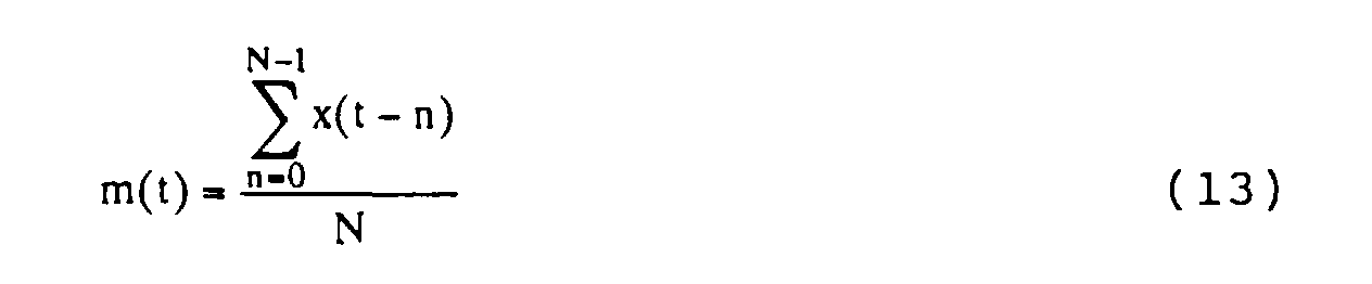
calculates the average m(t) of the five-sample input data
x(t) to x(t-4) according to the following expression and
sends the result to the
variance calculation circuit 32.
In the embodiment shown in Fig. 4, N equals 5 in the
expression (13).
The
variance calculation circuit 32 uses the input data
x(t) to x(t-4) input thereto and the average m(t) sent from
the
average calculation circuit 31 to calculate the variance
σ
x(t) 2 according to an expression (14) and outputs it as the
noise amount of the input data x(t).
In the same way as in the expression (13), N also equals 5
in the expression (14) in the embodiment shown in Fig. 4.
The variance σx(t) 2 serving as the noise amount is sent
to the input reliability calculation section 12 (shown in
Fig. 3). The input reliability calculation section 12
obtains the reciprocal of the variance σx(t) 2 as shown in the
following expression, and outputs it as the input
reliability αx(t).
αx(t) = 1σ2 x(t)
Fig. 6 shows an example structure of the output
reliability calculation section 13 shown in Fig. 3.
As shown in Fig. 6, the output reliability calculation
section 13 is formed of an operation section 41. The
operation section 41 receives the current input reliability
αx(t) sent from the input reliability calculation section 12
and the output reliability αy(t-1) obtained one sample before,
sent from the latch circuit 14. The operation section 41
adds the input reliability αx(t) and the output reliability
αy(t-1) according to the expression (4) and outputs the sum as
the current output reliability αy(t).
The operation of the NR processing circuit 100 shown in
Fig. 3 will be described below by referring to Figs. 7A and
7B and Fig. 8. The operation of the NR processing circuit
100 and the control of each functional block may be
implemented by each hardware block shown in the figures or
by software. Alternatively, a controller may control each
hardware.
As shown in Fig. 7A, the NR processing circuit 100 uses
five samples, the current input data x(t) and the input data
x(t-1) to x(t-4) obtained up to four samples before the
current one, to obtain the variance σx(t) 2 thereof, and
further obtains the reciprocal of the variance as the input
reliability αx(t).
The weight w(t) is obtained as shown in Fig. 7B with
the use of the input reliability αx(t) and the output
reliability αy(t-1) obtained one sample before, and the
weighted average of the input data x(t) and the output data
y(t-1) obtained one sample before is calculated according to
the weight w(t) to output the weighted average as the output
data y(t).
More specifically, as shown in a flowchart of Fig. 8,
the input data x(t) is input to the noise-amount estimate
section 1 (the latch circuit 111 and the noise-amount
calculation section 11) and to the noise removing section 2
(the weighting section 23) in a step S11.
In the next step S12, the noise-amount estimate section
1 estimates the noise amount of the input data x(t), and the
input reliability calculation section 12 of the noise
removing section 2 obtains the input reliability αx(t) from
the amount of noise.
More specifically, the latch circuit 111 of the noise-amount
estimate section 1 latches the received input data in
synchronization with the timing when the input data is
received, and sends it to the subsequent-stage latch circuit
112 and to the noise-amount calculation section 11. The
latch circuit 112 and the latch circuit 113 latch the input
data output from the previous- stage latch circuits 111 and
112 and send the data to the subsequent- stage latch circuits
113 and 114 and to the noise-amount calculation section 11,
respectively, in the same way as the latch circuit 111. The
latch circuit 114 latches the input data output from the
previous-stage latch circuit 113 and sends it to the noise-amount
calculation section 11. Therefore, the noise-amount
calculation section 11 receives the input data x(t-1) to
x(t-4) from the latch circuits 111 to 114, respectively, at
the same time when it receives the input data x(t). The
noise-amount calculation section 11 obtains the variance of
the input data x(t) to x(t-4) and sends it as the noise
amount of the input data x(t) to the input reliability
calculation section 12, as described above.
The input reliability calculation section 12 obtains
the reciprocal of the noise amount sent from the noise-amount
calculation section 11, and sends it as the input
reliability αx(t) of the input data x(t) to the output
reliability calculation section 13 and to the weight
calculation section 15.
At the timing when the input reliability calculation
section 12 sends the input reliability αx(t) to the weight
calculation section 15, the latch circuit 14 latches the
output reliability αy(t-1) output from the output reliability
calculation section 13 one sample before. In a step S13,
the weight calculation section 15 uses the input reliability
αx(t) sent from the input reliability calculation section 12
and the output reliability αy(t-1) latched by the latch circuit
14 to obtain the weight w(t) according to the expression (6).
This weight w(t) is sent to the weighting section 21 and the
operation section 22.
The weighting section 21, the operation section 22, the
weighting section 23, the operation section 24, and the
latch circuit 25 use the weight w(t) output from the weight
calculation section 15 to calculate the weighted average of
the input data x(t) and the output data y(t-1) obtained one
sample before, according to the expression (8).
Specifically, the weighting section 21 multiplies the
output of the latch circuit 25 by the weight w(t) sent from
the weight calculation section 15, and sends the product to
the operation section 24. The latch circuit 25 latches the
output data y(t-1) which the operation section 24 outputs
the last time, at the timing when the weight calculation
section 15 outputs the weight w(t). Therefore, the
weighting section 21 obtains the product w(t)y(t-1) of the
output data y(t-1) and the weight w(t) and sends it to the
operation section 24.
The operation section 22 subtracts the weight w(t) sent
from the weight calculation section 15, from one, and sends
the subtraction value, 1 - w(t), to the weighting section 23.
The weighting section 23 multiplies the output, 1 - w(t), of
the operation section 22 by the input data x(t) and sends
the multiplication result, (1 - w(t))x(t), to the operation
section 24.
The operation section 24 adds the output, w(t)y(t-1),
of the weighting section 21 and the output, (1-w(t))x(t), of
the weighting section 23. In other words, with the use of
the weight w(t) output from the weight calculation section
15, the weighted average of the input data x(t) and the
output data y(t-1) obtained one sample before is calculated
according to the expression (8).
This weighted average is output as the output data y(t)
in a step S15. The output data y(t) is sent to the latch
circuit 25 and latched.
In the next step S16, it is determined whether input
data still exists. When it is determined in the step S16
that input data to be processed still exists, the procedure
proceeds to a step S17 and the output reliability
calculation section 13 updates the output reliability.
Specifically, the output reliability calculation section 13
adds the input reliability αx(t) calculated in the step S12 by
the input reliability calculation section 12 and the output
reliability αy(t-1) obtained one sample before and latched by
the latch circuit 14, according to the expression (5) to
obtain the current output reliability αy(t), and sends it to
the latch circuit 14. Then, the procedure returns to the
step S11, and the same processing is repeated with the next
input data.
On the other hand, when it is determined in the step
S16 that input data to be processed does not exist, the
processing is terminated.
As described above, the input reliability αx(t) of the
current input data x(t) and the output reliability αy(t-1)
obtained one sample before are added to calculate the weight
w(t). Then, according to the weight w(t), the weighted
average of the current input data x(t) and the output data
y(t-1) obtained one sample before is calculated, and the
average is output as the output data y(t) serving as the
processing result of the input data x(t). The output
reliability αy(t) of the output data y(t) is then obtained
(updated) by adding the current input reliability αx(t) to the
output reliability αy(t-1) obtained one sample before. In the
same way, input data x(t+1), x(t+2), ... is sequentially
processed. Therefore, the weight w(t) is learned such that
portions having high noise levels are not much taken into
account and portions having low noise levels are
sufficiently taken into account in previous input data. In
other words, the NR processing circuit 100 obtains a weight
w(t) adaptive to input data, and as a result, improves the
output data every moment as learning of the weight w(t)
proceeds. The NR processing circuit 100 effectively removes
noise from the input data and outputs data.
In the above-described case, since the NR processing
circuit 100 uses the reciprocal of the variance of input
data as the input reliability αx(t), the input reliability
αx(t) indicates the dispersion of the input data within a
predetermined time range. Therefore, when the degree of
noise included in input data, for example, the S/N ratio of
the input data, varies, the NR processing circuit 100 very
effectively removes the noise.
When the reciprocal of the variance of the input data
is used as the input reliability αx(t) in the NR processing
circuit 100, however, the effect of noise removal is
slightly lowered for a local change of a noise level, namely,
a change in a very narrow area, due to the nature of the
variance.
The local change of a noise level can be effectively
handled by using, for example, the reciprocal of the error
square of the current input data against the average of
input data, as the input reliability αx(t).
In this case, the input reliability αx(t) is calculated
in the following way.
Specifically, for example, the
NR processing circuit
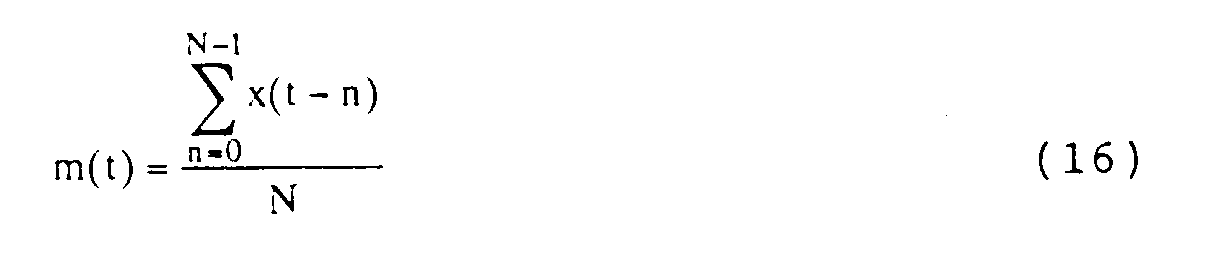
100 calculates the average m(t) of five-sample input data
x(t) to x(t-4) according to an expression (16) as shown in
Fig. 9.
In an embodiment shown in Fig. 9, N equals 5 in the
expression (16).
With the use of the input data x(t) and the average
m(t), the NR processing circuit 100 calculates an error
square dx(t) 2 of the input data x(t) against the average m(t)
according to an expression (17).
d2 x(t)=(x(t)-m(t))2
Then, the reciprocal of the error square dx(t) 2 is
obtained according to the following expression to obtain the
input reliability αx(t).
αx(t) = 1d2 x(t)
As described above, the method using the reciprocal of
the error square as the input reliability αx(t) is especially
effective when the average m(t) is close to the true value.
In the above description, the input reliability αx(t) is
obtained based on either the variance αx(t) 2 or the error
square dx(t) 2. It can be also obtained based on both.
Specifically, for example, the sum of the reciprocal of the
variance σx(t) 2 and the reciprocal of the error square dx(t) 2
can be used as an input reliability αx(t).
Since the variance σx(t) 2 indicates the degree of the
local dispersion of input data in a rather wide area and the
error square dx(t) 2 indicates the degree of the local
dispersion of the data in a narrow area, when a combination
of these factors is used as the input reliability αx(t), even
if the input data has a changing S/N ratio and a local level
of noise included in the input data also changes, the noise
is effectively removed.
When input data x(t) is one-dimensional data, such as
audio data, output data y(t-1) is obtained as a result of
processing of input data x(t-1), which is one sample before
the input data x(t). When input data x(t) is two-dimensional
data, such as image data, output data y(t-1) is
obtained as a result of processing of input data x(t-1),
which is one frame (or field) before the input data x(t).
Specifically, when a pixel (pixel value of the pixel)
in the t-th frame is called x(t); noise is removed according
to the expression (8) from the pixel x(t) serving as an
input pixel; and the resultant output pixel is output, a
pixel in the (t-1)-th frame, disposed at the same position
in space as the input pixel x(t) in the t-th frame is called
an input pixel x(t-1). An output pixel y(t-1) indicates the
pixel obtained by removing noise from the input pixel x(t-1).
When an image serving as input data has no motion, in
other words, when an image serving as input data is still,
no problem occurs. When an image serving as input data has
motion (when noise is removed from a motion image), since
the true value of an input pixel x(t) differs from that of
an input pixel x(t-1) obtained one frame before and disposed
as the same position as the input pixel x(t), the output
reliability αy(t-1) of the output pixel y(t-1) corresponding to
the input pixel x(t-1) obtained one frame before and having
a different true value from the input pixel x(t) is not
reliable to obtain the output pixel y(t), which is obtained
by removing noise from the input pixel x(t).
In other words, when an image serving as input data has
motion, the output reliability αy(t-1) of the output pixel y(t-1),
used to obtain the output pixel y(t) corresponding to
the input pixel x(t), is affected by the motion amount of
the input pixel x(t) and is reduced by the amount
corresponding to the motion amount.
The motion amount of the input pixel x(t) is called
m(t), and the output reliability αy(t-1) is changed to (1.0 -
m(t)) x αy(t-1), which serves as a compensation term. In the
present embodiment, the motion amount m(t) is set to a real
number between 0 and 1. The motion amount m(t) is 0 when
the input pixel x(t) is completely still. The motion amount
m(t) increases as the input pixel x(t) moves largely. The
motion amount m(t) reaches 1 when the input pixel x(t) moves
largely (it moves completely) and it is considered that the
true value of the input pixel x(t) is irrelevant to that of
the input pixel x(t-1) disposed at the same position as the
input pixel x(t), on the frame one frame before.
In this case, the output reliability αy(t) to be obtained
by the expression (5) is obtained by the following
expression.
αy(t) = (1.0 - m(t))αy(t-1) + αx(t)
According to the expression (19), when the motion amount
m(t) is 0, the output reliability αy(t) (this-time output
reliability) of the output pixel y(t) is obtained by the use
of the output reliability αy(t-1) (previous-time output
reliability) of the output pixel y(t-1) obtained one frame
before. On the other hand, when the motion amount m(t) is 1,
the output reliability αy(t-1) obtained at the previous time
is ignored (not used), in other words, the input reliability
which has been summed up so far is discarded, and the output
reliability αy(t) is obtained.
In this case, the weight w(t) to be obtained by the
expression (6) is obtained by the following expression.
w(t) = (1 - m(t))αy(t-1)/((1 - m(t)αy(t-1) + αx(t))
The weight 1 - w(t) indicated by the expression (7) is
obtained by the following expression.
1 - w(t) = αx(t)/((1 - m(t)αy(t-1) + αx(t))
Fig. 10 shows a detailed example structure of the NR
processing circuit shown in Fig. 1 in a case in which noise
is removed from an image with the motion amount m(t)
described above being introduced. In Fig. 10, the same
symbols as those used in Fig. 3 are assigned to the portions
corresponding to those shown in Fig. 3, and descriptions
thereof are appropriately omitted. More specifically, the
NR processing circuit shown in Fig. 10 has basically the
same structure as that shown in Fig. 3 except that a motion-amount
calculation section 16 is newly provided.
The motion-amount calculation section 16 receives the
input pixel x(t) as input data. The motion-amount
calculation section 16 obtains the motion amount m(t) of the
input pixel x(t) and sends it to the output reliability
calculation section 13.
The motion amount m(t) of the input pixel x(t)
corresponds to the value corresponding to the difference
between the true value of the input pixel x(t) and that of
the input pixel x(t-1) disposed at the same position as the
input pixel x(t), on the frame one frame before, that is,
the change of the true value generated by the movement (the
movement of an image portion displayed at the input pixel
x(t)) of the input pixel x(t). The motion amount m(t) is
basically obtained from the difference (x(t) - x(t-1)) of
the input pixels x(t) and x(t-1).
The difference between the input pixels x(t) and x(t-1)
includes not only the difference between the true values
thereof but also a change of noise (the difference between
the noise included in the input pixel x(t) and that included
in the input pixel x(t-1)). It is preferred that the
difference between the input pixels x(t) and x(t-1) be
obtained with the change of noise being removed as much as
possible.
The motion-amount calculation section 16 obtains the
motion amount m(t) as shown in Fig. 11A and Fig. 11B.
The motion-amount calculation section 16 sets the input
pixel x(t) for which an motion amount m(t) is to be obtained
to an aimed-at pixel and forms a block having a
predetermined size with the aimed-at pixel (indicated by a
hatched circle in Fig. 11A) placed at the center of the
block. In Fig. 11A, a nine-by-nine input-pixel block is
generated. The size of the block is not limited to this
size. A seven-by-seven pixel block may be used. In the
nine-by-nine input-pixel block, pixels (indicated by black
circles in Fig. 11) having differences in level from the
aimed-at pixel not more than a predetermined threshold are
detected. The differences between the detected input pixels
indicated by the black circles and the aimed-at pixel, and
those disposed at the same positions on the frame one frame
before are calculated. The average of the differences is
obtained as the difference x(t) - x(t-1) of the input pixels
x(t) and x(t-1) in a condition in which the change of noise
in the spatial direction is removed as much as possible.
As the threshold used to detect input pixels in a block
as described above, for example, a value about twice the
standard deviation of the noise amount obtained by the
noise-amount calculation section 11 can be used.
The motion-amount calculation section 16 converts the
difference x(t) - x(t-1) by a conversion function, such as
that shown in Fig. 11B, to obtain a motion amount m(t) which
ranges from 0 to 1.
In the embodiment shown in Fig. 11B, the motion amount
m(t) is 0 when the difference x(t) - x(t-1) is equal to or
less than a predetermined threshold TH0. The motion amount
m(t) increases in proportion to the difference x(t) - x(t-1)
when the difference x(t) - x(t-1) exceeds the predetermined
threshold TH0. When the difference x(t) - x(t-1) is equal
to or more than a predetermined threshold TH1 (> TH0), the
motion amount m(t) is set to 1.
As the threshold TH0, for example. 0 can be used. As
the threshold TH1, for example, a value about three times
the standard deviation of the noise amount obtained by the
noise-amount calculation section 11 can be used.
In the above case, the motion-amount calculation
section 16 calculates the differences between the input
pixels in the frame where the aimed-at pixel is disposed and
the corresponding input pixels in the frame one frame before
to obtain the motion amount m(t). The motion amount m(t)
can be obtained in other ways, such as a way in which the
differences between input values in the frame where the
aimed-at pixel is disposed and the corresponding output
pixels in the frame one frame before are calculated.
In Fig. 11B, the motion-amount calculation section 16
converts the difference x(t) - x(t-1) to the motion amount
m(t) by a linear function when the difference falls in the
range from the threshold TH0 to the threshold TH1 both
inclusive. The difference x(t) - x(t-1) may be converted to
a motion amount m(t) by a non-linear function.
Fig. 12 shows an example structure of the output
reliability calculation section 13 shown in Fig. 10. In Fig.
12, the same symbols as those used in Fig. 6 are assigned to
the portions corresponding to those shown in Fig. 6. In Fig.
12, the output reliability calculation section 13 is formed
with operation sections 51 and 52 being newly added.
The operation section 51 receives the motion amount
m(t) obtained by the motion-amount calculation section 16.
The operation section 51 subtracts the motion amount m(t)
from 1 and sends the difference 1 - m(t) to the operation
section 52. The operation section 52 receives the output
reliability αy(t-1) obtained at the previous time, from the
latch circuit 14 in addition to the difference 1 - m(t) sent
from the operation section 51. The operation section 52
uses 1 - m(t) as a compensation term, multiplies the output
reliability αy(t-1) obtained at the previous time by the
compensation term, and outputs the product (1 - m(t))αy(t-1) to
an operation section 41 as a compensation result obtained by
compensating the output reliability αy(t-1) obtained at the
previous time correspondingly to the motion amount m(t).
The operation section 41 adds the input reliability αx(t)
obtained this time sent from the input reliability
calculation section 12 to the output (1 - m(t))αy(t-1) of the
operation section 52, and outputs the sum as the output
reliability αy(t) obtained this time. In other words, the
output reliability calculation section 13 obtains the
compensated output reliability αy(t), indicated by the
expression (19).
As described above, in the NR processing circuit shown
in Fig. 10, the output reliability αy(t-1) is compensated
according to the motion amount m(t) of the input pixel x(t)
and then the weight w(t) is obtained according to the
compensated output reliability. Since the output pixel y(t)
corresponding to the input pixel x(t) is obtained according
to the weight w(t), noise is effectively removed from the
input pixel x(t) to generate the output pixel y(t).
In the embodiment shown in Fig. 10, since x(t-1) is the
input pixel obtained one frame before x(t) as described
above, the latch circuits 114, 14, and 25 latch (delay) data
input thereto for the one-frame period and output.
As described above, since the latch circuits 111 to 114
in the NR processing circuit shown in Fig. 10, which remove
noise from an image, delay the input pixel x(t) for the one-frame
period, the noise-amount calculation section 11
obtains the variance of the input pixels x(t) to x(t-4)
disposed at the same position as the input pixel x(t) in the
previous five frames, including the frame for the input
pixel x(t) to be processed, as the noise amount. When the
input pixels x(t) to x(t-4) have motion, because the
variance is affected by the motion in the image, the noise
amount of the input pixel x(t), which is the variance of the
input pixels x(t) to x(t-4), is inaccurate due to the effect
of the motion. The input reliability αx(t) obtained by the
input reliability calculation section 12 by the use of the
noise amount becomes also inaccurate, and this is not
preferable.
It is possible, for example, that the motion vector of
the input pixel x(t) is obtained to achieve motion
compensation, and the noise amount of the input pixel x(t)
is obtained by using the image obtained after the motion
compensation.
In this case, however, a motion-vector detecting
apparatus for detecting a motion vector and a motion
compensation apparatus for achieving motion compensation are
separately required.
The noise amount of the input pixel x(t) can, for
example, be obtained (estimated) in the following way.
When it is assumed that noise included in an image
changes in terms of time but does not change spatially, the
image is the sum (shown in Fig. 13(C)) of an image (image
formed of true values, hereinafter called the original
image) having no noise (shown in Fig. 13(A)) and an image
(hereinafter called a noise image) shown in Fig. 13(B) which
has noise changing in frames but being constant spatially.
For an image having noise such as that shown in Fig.
13(C), when the distribution of the errors of pixel values
against the original image, that is, the variance (or
standard deviation) of the pixel values, is defined as the
noise amount of the image having noise, the noise amount can
be relatively precisely estimated in the following way.
As shown in Fig. 15A, the noise-amount estimate section
1 sequentially sets each pixel constituting one frame of an
image having noise to an aimed-at pixel, and calculates the
variance of pixels included in a local area (in the spatial
direction) which has the aimed-at pixel at the center. As
indicated in Fig. 15B, the noise-amount estimate section 1
obtains the histogram of the variances in the frame, and
regards the variance corresponding to the maximum frequency
as a noise mount included in each pixel constituting the
frame. The noise mount is estimated, for example, as shown
in Fig. 13(D).
The noise-amount estimate section 1 in the NR
processing circuit shown in Fig. 10 obtains the noise amount
of the input pixel as described above. Fig. 16 shows an
example structure of the noise-amount estimate section 1.
A frame memory 61 receives an image (input image)
having noise. The frame memory 61 stores the input image
having noise in units of frames.
A local-area-variance calculation section 62
sequentially sets each (input) pixel constituting the input
image stored in the frame memory 61 to an aimed-at pixel,
calculates the variance of the input pixels included in a
local area which has the aimed-at pixel at the center, and
sends it to a variance-histogram storage memory 63. When
the foregoing variance calculation is finished with all
input pixels constituting the input image stored in the
frame memory 61 being set to aimed-at pixels, the local-area-variance
calculation section 62 further sends a
termination signal indicating that the variance calculation
has been terminated, to a histogram-output-signal generator
64.
The variance-histogram storage memory 63 generates the
histogram of the variances of the input pixels constituting
the input image stored in the frame memory 61, the variances
being sent from the local-area-variance calculation section
62. More specifically, when the variance-histogram storage
memory 63 receives the variance of input pixels from the
local-area-variance calculation section 62, it increments by
1 the value stored at the address corresponding to the
variance. Values stored in the variance-histogram storage
memory 63 are reset to 0 by a reset signal sent from a peak-position
calculation section 66, described later.
When the histogram-output-signal generator 64 receives
the termination signal from the local-area-variance
calculation section 62, it outputs to a switch 65 a
histogram-output signal indicating that the histogram should
be output. When the switch 65 receives the histogram-output
signal from the histogram-output-signal generator 64, it
temporarily changes its state from off to on, and sends the
variance histogram stored in the variance-histogram storage
memory 63 to the peak-position calculation section 66.
The peak-position calculation section 66 receives the
variance histogram sent from the variance-histogram storage
memory 63 through the switch 65, obtains the peak value of
the histogram, and outputs the variance corresponding to the
peak value as the estimate of the noise amount included in
each input pixel constituting the input image. The peak-position
calculation section 66 sends the reset signal to
the variance-histogram storage memory 63 at the timing when
it receives the variance histogram stored in the variance-histogram
storage memory 63.
Noise-amount estimate processing for estimating the
noise amount of an input pixel by the noise-amount estimate
section 1 shown in Fig. 16 will be described below by
referring to a flowchart shown in Fig. 17.
When an input image of one frame is input to the noise-amount
estimate section 1, the noise-amount estimate
processing shown in Fig. 17 is executed.
In the noise-amount estimate processing, the one-frame
input image is first stored in the frame memory 61 in a step
S21, and the processing proceeds to a step S22. In the step
S22, the local-area-variance calculation section 62 sets a
predetermined input pixel constituting the input image
stored in the frame memory 61 to an aimed-at pixel, and
calculates the variance of input pixels included in a local
area which has the aimed-at pixel at the center.
The variance is sent from the local-area-variance
calculation section 62 to the variance-histogram storage
memory 63. The variance-histogram storage memory 63
increments by 1 the value stored at the address
corresponding to the variance sent from the local-area-variance
calculation section 62 in a step S23 to update the
frequency of the variance.
Then, in a step S24, the local-area-variance
calculation section 62 determines whether the variance
calculation has been finished for all input pixels
constituting the input image stored in the frame memory 61,
which are set to aimed-at pixels. When the local-area-variance
calculation section 62 determines in the step S24
that the variance calculation has not yet been finished for
all the input pixels stored in the frame memory 61, it sets
an input pixel which has not yet been set to an aimed-at
pixel to an aimed-at pixel, the processing returns to the
step S22, and the same processes are repeated. With the
processes from the steps S22 to S24 being repeated as
described above, the variance-histogram storage memory 63
generates a variance histogram for the input pixels
constituting the input image stored in the frame memory 61.
On the other hand, when the local-area-variance
calculation section 62 determines in the step S24 that the
variance calculation has been finished for all the input
pixels stored in the frame memory 61, in other words, when
the variance-histogram storage memory 63 has generated a
variance histogram for all the input pixels constituting the
input image stored in the frame memory 61, the local-area-variance
calculation section 62 sends the termination signal
to the histogram-output-signal generator 64. When the
histogram-output-signal generator 64 receives the
termination signal, it outputs the histogram-output signal
to the switch 65. The switch 65 is temporarily changed from
the off state to the on state, and the variance histogram
stored in the variance-histogram storage memory 63 is sent
to the peak-position calculation section 66.
When the peak-position calculation section 66 receives
the variance histogram from the variance-histogram storage
memory 63 through the switch 65, it obtains the peak value
of the histogram in a step S25, and the processing proceeds
to a step S26. In the step S26, the peak-position
calculation section 66 outputs the variance corresponding to
the peak value in the histogram as the estimated noise
amount included in each input pixel constituting the input
image, and sends the reset signal to the variance-histogram
storage memory 63. The values stored in the variance-histogram
storage memory 63 are reset to 0, and the noise-amount
estimate processing is terminated.
As described above, since the noise-amount estimate
section 1 calculates the variance in the local area
including each input pixel constituting one frame, obtains
the peak value of the variance histogram, and uses the
variance corresponding to the peak value as the noise amount
included in the input pixel, the noise amount of each pixel
in the one frame is relatively precisely estimated by the
use of just the one frame without newly providing a motion-vector
detecting apparatus and a motion compensation
apparatus.
When a variance is obtained by the use of all pixels
constituting one frame, the variance is affected not only by
the variance of noise included in the one-frame image but
also by the variance of the image (original image).
Therefore, it is difficult to precisely estimate the noise
included in the pixels with the use of the variance obtained
from all pixels constituting the one frame.
On the other hand, as described above, when a local
area including each input pixel is used for the input pixel
constituting one frame, the local area may have the variance
of noise and that of the original image in a mixed manner,
or may mainly have the variance of noise. The local area
which mainly has the variance of noise corresponds to a flat
part or a nearly flat part in the original image.
When the variance histogram of local areas including
input pixels constituting one frame is generated for a usual
image except an image having a number of edges, it is likely
in general that the peak corresponds to the variance of a
local area mainly having a noise variance. The noise-amount
estimate processing executed by the noise-amount estimate
section 1 shown in Fig. 16 uses this nature to estimate the
noise amount relatively precisely.
Fig. 18 shows the variance histograms of local areas
such as those described above, for the original image which
is a usual image, a noise image, and an input image (image
having noise) obtained by superposing the noise image on the
original image.
In Fig. 18, a solid line, a two-dot chain line, and a
thin dotted line indicate the variance histograms for the
input image, the noise image, and the original image,
respectively. It is understood that the position of the
peak of the histogram for the input image almost matches
that of the peak of the histogram for the noise image. A
five-by-five square block is used as a local area when the
histograms shown in Fig. 18 is obtained.
Fig. 19 shows a simulation result of an estimated noise
amount included in an input image, obtained by the noise-amount
estimate processing shown in Fig. 17.
In Fig. 19, a solid line indicates the variance of a
noise image, and a dotted line indicates a variance serving
as a noise amount obtained by the noise-amount estimate
processing for an input image in which the noise image is
superposed on the original image.
The noise image used in the simulation has smaller
variances between the 20th frame to the 40th frame than in
the other frames. It is understood from Fig. 19 that the
noise amount is relatively precisely estimated for the input
image in which the noise image is superposed.
The present invention can be implemented by special
hardware or by making a computer execute a program for
achieving the above processing.
In the present embodiment, the description has been
made for the present invention in terms of removing noise.
As described above, since input data is processed such that
output data is improved as time elapses, the present
invention can also be applied, for example, to a case in
which the waveform of input data is shaped (equalized).
In the noise-amount estimate processing shown in Fig.
17, a noise amount common to each pixel constituting a one-frame
image is estimated. The noise amount may be estimated
for each area formed by diving the one-frame image. The
noise amount may also be estimated for a plurality of frames
in common.
As described above, according to the image processing
apparatus and the image processing method according to the
embodiment of the present invention, the input reliability
indicating the reliability of an input pixel and the output
reliability indicating the reliability of an output pixel
are calculated, the motion amount of the input pixel is
detected, and the output reliability is compensated
according to the motion amount of the input pixel. The
input pixel is processed according to the input reliability
and the compensated output reliability, and the output pixel
is output. Therefore, noise is effectively removed from the
input pixel to generate the output pixel.
In addition, according to the image processing
apparatus and the image processing method according to the
embodiment of the present invention, the variance of a local
area including each pixel constituting one screen is
calculated, and a variance histogram is generated. The
amount of noise included in the pixel is obtained according
to the histogram. Therefore, the amount of noise included
in the pixel is relatively precisely estimated.
The series of processing shown in Figs. 8 and 17 can be
implemented by hardware or software. When the series of
processing is achieved by software, a program constituting
the software is installed into a computer which is built in
the NR processing circuit 100 serving as special hardware or
into a general-purpose computer.
Recording media which store the program for executing
the series of processing described above will be described
below by referring to Figs. 20A, 20B, and 20C. The program
is installed into a computer and is made executable by the
computer.
The program is recorded in advance into a hard disk 102
or a semiconductor memory 103 serving as a recording medium
which is built in a computer 101, as shown in Fig. 20A.
Alternatively, the program is recorded temporarily or
perpetually into recording media, such as a floppy disk 111,
a compact disc read-only memory (CD-ROM) 112, a magnetooptical
(MO) disk 113, a digital versatile disk (DVD) 114, a
magnetic disk 115, and a semiconductor memory 116, as shown
in Fig. 20B.
The program is installed in the computer from the
above-described recording medium. Alternatively, the
program is transferred by radio from a downloading site 121
to the computer 101 through an artificial satellite for
digital satellite broadcasting, or to the computer 101 by
wire through a network 131 such as a local area network
(LAN) or the Internet; and is installed into the hard disk
102, built in the computer 101, as shown in Fig. 20C.
In the present specification, the steps describing the
programs for executing various types of processing are not
necessarily processed in a time sequential manner in the
order in which the steps are described in the flowcharts.
Processing to be executed in parallel or individually, such
as parallel processing or processing by objects, is also
included.
Fig. 21 shows an example structure of the computer 101
shown in Figs. 20A, 20B, and 20C.
The computer 101 includes a central processing unit
(CPU) 142, as shown in Fig. 21. The CPU 142 is connected to
an input and output interface 145 through a bus 141. When
the user operates an input section 147 formed of a keyboard
and a mouse to input a command through the input and output
interface 145, the CPU 142 executes a program stored in a
read-only memory (ROM) 143 corresponding to the
semiconductor memory 103 shown in Fig. 20A. Alternatively,
the CPU 142 loads into a random access memory (RAM) 144 a
program stored in the hard disk 102; a program transferred
through the satellite 122 or the network 131, received by a
communication section 148, and installed into the hard disk
102; or a program read from the floppy disk 111, the CD-ROM
112, the MO disk 113, the DVD 114, or the magnetic disk 115
which is loaded into a drive 149, and installed into the
hard disk 102; and executes it. The CPU 142 outputs the
processing result, for example, through the input and output
interface 145 to a display section 146 formed of a liquid-crystal
display (LCD), as required.
In so far as the embodiments of the invention described
above are implemented, at least in part, using software-controlled
data processing apparatus, it will be appreciated
that a computer program providing such software control and a
storage medium by which such a computer program is stored are
envisaged as aspects of the present invention.