EP1058105A1 - Measuring drive train backlash with a restraining member - Google Patents
Measuring drive train backlash with a restraining member Download PDFInfo
- Publication number
- EP1058105A1 EP1058105A1 EP00100839A EP00100839A EP1058105A1 EP 1058105 A1 EP1058105 A1 EP 1058105A1 EP 00100839 A EP00100839 A EP 00100839A EP 00100839 A EP00100839 A EP 00100839A EP 1058105 A1 EP1058105 A1 EP 1058105A1
- Authority
- EP
- European Patent Office
- Prior art keywords
- drive
- distance
- train
- movement
- measuring
- Prior art date
- Legal status (The legal status is an assumption and is not a legal conclusion. Google has not performed a legal analysis and makes no representation as to the accuracy of the status listed.)
- Granted
Links
- 230000000452 restraining effect Effects 0.000 title claims description 5
- 238000000034 method Methods 0.000 claims abstract description 31
- 230000003287 optical effect Effects 0.000 claims abstract description 19
- 238000005286 illumination Methods 0.000 claims description 4
- 238000004092 self-diagnosis Methods 0.000 abstract description 5
- 238000005259 measurement Methods 0.000 description 5
- 230000003044 adaptive effect Effects 0.000 description 2
- 238000003384 imaging method Methods 0.000 description 2
- 238000004519 manufacturing process Methods 0.000 description 2
- 230000000903 blocking effect Effects 0.000 description 1
- 230000008878 coupling Effects 0.000 description 1
- 238000010168 coupling process Methods 0.000 description 1
- 238000005859 coupling reaction Methods 0.000 description 1
- 230000001419 dependent effect Effects 0.000 description 1
- 230000000007 visual effect Effects 0.000 description 1
Images

Classifications
-
- F—MECHANICAL ENGINEERING; LIGHTING; HEATING; WEAPONS; BLASTING
- F16—ENGINEERING ELEMENTS AND UNITS; GENERAL MEASURES FOR PRODUCING AND MAINTAINING EFFECTIVE FUNCTIONING OF MACHINES OR INSTALLATIONS; THERMAL INSULATION IN GENERAL
- F16H—GEARING
- F16H57/00—General details of gearing
- F16H57/12—Arrangements for adjusting or for taking-up backlash not provided for elsewhere
-
- G—PHYSICS
- G01—MEASURING; TESTING
- G01M—TESTING STATIC OR DYNAMIC BALANCE OF MACHINES OR STRUCTURES; TESTING OF STRUCTURES OR APPARATUS, NOT OTHERWISE PROVIDED FOR
- G01M13/00—Testing of machine parts
- G01M13/02—Gearings; Transmission mechanisms
-
- G—PHYSICS
- G01—MEASURING; TESTING
- G01M—TESTING STATIC OR DYNAMIC BALANCE OF MACHINES OR STRUCTURES; TESTING OF STRUCTURES OR APPARATUS, NOT OTHERWISE PROVIDED FOR
- G01M13/00—Testing of machine parts
- G01M13/02—Gearings; Transmission mechanisms
- G01M13/021—Gearings
-
- Y—GENERAL TAGGING OF NEW TECHNOLOGICAL DEVELOPMENTS; GENERAL TAGGING OF CROSS-SECTIONAL TECHNOLOGIES SPANNING OVER SEVERAL SECTIONS OF THE IPC; TECHNICAL SUBJECTS COVERED BY FORMER USPC CROSS-REFERENCE ART COLLECTIONS [XRACs] AND DIGESTS
- Y10—TECHNICAL SUBJECTS COVERED BY FORMER USPC
- Y10T—TECHNICAL SUBJECTS COVERED BY FORMER US CLASSIFICATION
- Y10T74/00—Machine element or mechanism
- Y10T74/19—Gearing
- Y10T74/19623—Backlash take-up
Definitions
- the present invention relates generally to measurement of backlash in systems of gears in drive trains and, more particularly, to the optical measurement of backlash in systems of gears in drive trains.
- the precise positioning of one mechanism with respect to a reference device is often accomplished by utilizing a system of gears. Power, often supplied by an electric motor, is transferred via the gears to move the mechanism. Precise positioning is dependent upon so called backlash or the looseness in the coupling between the gears. The greater the backlash, the less precise is the positioning of the mechanism with respect to the reference device. Some backlash is inevitable as it is impossible to manufacture gears that exactly mate with one another.
- Backlash can be measured in gear systems by blocking movement of the driven gear and measuring the movement of the drive gear between its resulting limits of motion. This method is, however, time consuming, labor intensive, and not conducive to mass production of identical systems. Often backlash is measured in a representative number of systems and the average of these measurements is used as the backlash for all similar systems. This nominal backlash is then used as an offset in the control system. This method suffers from several disadvantages. In particular, unit-to-unit variations in backlash are not accounted for, and backlash changes over time are not accounted for.
- the present invention discloses methods and apparatus for quantifying the amount of backlash present in drive trains.
- the techniques discussed lend themselves to self diagnosis of these systems.
- Optical methods are used. Such technique are useful in autochanger drive systems, but are applicable to all systems involving the driven motion of devices.
- the backlash problem is found in gear train systems, as well as other forms of driven motion devices.
- the invention is not limited to gear trains, but is applicable to all forms of driven motion devices.
- the driven system could be, but not limited to, Digital Linear Tape systems.
- a movable device is positioned in front of an optical target, and the drive train is biased in one direction.
- the imaging system looks at a target located on a fixed frame and measures its location.
- the drive train is then reversed and the angle of rotation measured as the number of counts on an encoder disk is counted by a second optical system.
- the target located on the fixed frame is used to determine the actual movement of the moveable device.
- a primary advantage of the embodiments as described in the present patent document over prior methods lies in the fact that these methods lend themselves to self diagnosis, since measurement of the backlash in a robotic system can be performed periodically throughout the life of the drive train. If the degree of the backlash reaches a predefined limit, the robotic system can inform the user that the drive train is wearing out.
- a further advantage is that these methods also lend themselves to adaptive control.
- the robotic system can accurately compensate for changes in backlash with time. This ability allows for accurate positioning throughout the life of the drive train.
- the present patent document relates to a novel method and apparatus for quantifying the amount of backlash present in drive trains.
- the present document discloses techniques lending itself to self diagnosis of the drive train systems. Optical methods are used. The technique are useful in autochanger drive systems, but are applicable to all systems involving the driven motion of devices.
- like elements are identified with like reference numerals.
- Figure 1 is a drawing of a drive train 100 with backlash 110 as described in various representative embodiments of the present patent document.
- Figure 1 demonstrates the backlash problem inherent in driven motion devices.
- This backlash problem in figure 1 results from the fact that a first gear-tooth 112 on a first gear 114 must travel the distance 114 , also referred to herein as backlash 110 and the backlash distance 110 , before motion is imparted by the first gear 114 to a second gear 116 .
- This motion is imparted by means of contact between the first-gear tooth 112 and the second gear-tooth 118 .
- gear train systems are used in figure 1 and subsequent drawings for illustrative purposes only.
- the backlash problem is inherent in other forms of driven motion devices.
- the invention is not limited to gear trains. It is applicable to all forms of driven motion devices.
- Figure 2 is a drawing of a robotic system 200 as described in various representative embodiments of the present patent document.
- the robotic system 200 could be used in, but not limited to, Digital Linear Tape systems.
- a first force 205 is applied to the drive train 100 until a first device 210 moves in a first direction 215 to a first position 220 , wherein the drive train 100 is attached to the first device 210 and is moveably attached to a second device 225 and wherein a restraining member 230 is attached to the second device 225 and prevents movement of the first device 210 from the first position 220 in the first direction 215 .
- first motion transducer 235 Also shown in figure 2 is a first motion transducer 235 , wherein the first motion transducer 235 comprises a first target 240 attached to the second device 225 and a first optical detector 245 attached to the first device 210 .
- the first optical detector 245 detects an image from the first target 240 and uses that image to identify the position of the first device 210 relative to the second device 225 which in figure 2 is the first position 220 .
- a more complete discussion of the first target 240 will be provided later in this document.
- figure 2 shows a second motion transducer 250 comprising a second target 255 and a second optical detector 260 .
- the second target 255 in the preferred embodiment comprises a pattern of optically reflecting stripes on a gear providing motion to the first device 210 .
- the second motion transducer 250 measures the distance that the drive train 100 moves by counting the optically reflecting stripes passing under the second optical detector 260 .
- Figure 3 is another drawing of the robotic system 200 of figure 2 as described in various representative embodiments of the present patent document.
- Figure 3 shows the first device 210 in a second position 320 .
- a second force 305 is applied to the drive train 100 until the first device 210 moves in a second direction 315 to the second position 320 .
- a first device movement distance 370 is the distance between the first position 220 and the second position 320 and is the distance moved by the first device 210 between these two positions.
- the drive-train-movement-distance 380 could be either correspond to a measure of a linear movement or to an angular movement as in figure 3.
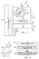
- Figure 4 is drawing of the first target 240 as viewed from section A-A of figures 2 and 3 as described in various representative embodiments of the present patent document.
- the preferred embodiment of the first optical detector 245 is a linear array optical detector.
- the number of pixels in the first optical detector 245 receiving illumination from the first target 240 corresponds to the position of the first device 210 with respect to the second device 225 . More pixels are illuminated when the first device 210 is at the first position 220 shown in figure 2 than when it is at the second position 255 shown in figure 3.
- First and second first-target-positions 421 , 422 from which the first optical detector 245 receives illumination when the first device 210 is at the first and second positions 220 , 320 are shown on the first target 240 in figure 4.
- the first motion transducer 235 and the components thereof are disclosed, in part, in the following United States Patent application: serial number 09/290,807 of Gardner et al. for CALIBRATION SYSTEM FOR AN IMAGING APPARATUS AND METHOD, filed on April 13, 1999 (attorney docket number 10971593-1) which is hereby incorporated by reference for all that is disclosed therein.
- Figure 5 is a flow chart of the method steps performed in computing the backlash 110 from measured values as described in various representative embodiments of the present patent document.
- Figure 5 is a flow chart of the method steps performed in computing the backlash 110 .
- a conversion factor is computed, wherein the conversion factor is the ratio of the distance that the first device 210 would move in response to a unit length movement of the drive-train-representative-point 375 in the absence of any backlash 110 .
- Block 510 then transfers control to block 520 .
- Block 520 The drive-train-movement-distance 380 is then multiplied by the conversion factor to obtain a converted-drive-train-movement-distance. Block 520 then transfers control to block 530 .
- the converted-drive-train-movement-distance is subtracted from the first-device-movement-distance to obtain the backlash 110 .
- optical methods for quantifying the amount of backlash present in the drive train are used.
- a primary advantage of the embodiments as described in the present patent document over prior methods lies in the fact that these methods lend themselves to self diagnosis, since measurement of the backlash in a robotic system can be performed periodically throughout the life of the drive train. If the degree of the backlash reaches a predefined limit, the robotic system can inform the user that the drive train is wearing out.
- a further advantage is that these methods also lend themselves to adaptive control.
- the robotic system can accurately compensate for changes in backlash with time. This ability allows for accurate positioning throughout the life of the drive train.
Landscapes
- Engineering & Computer Science (AREA)
- General Engineering & Computer Science (AREA)
- Physics & Mathematics (AREA)
- General Physics & Mathematics (AREA)
- Mechanical Engineering (AREA)
- Length Measuring Devices By Optical Means (AREA)
- Length Measuring Devices With Unspecified Measuring Means (AREA)
- Control Of Position Or Direction (AREA)
Abstract
Description
- The present invention relates generally to measurement of backlash in systems of gears in drive trains and, more particularly, to the optical measurement of backlash in systems of gears in drive trains.
- The precise positioning of one mechanism with respect to a reference device is often accomplished by utilizing a system of gears. Power, often supplied by an electric motor, is transferred via the gears to move the mechanism. Precise positioning is dependent upon so called backlash or the looseness in the coupling between the gears. The greater the backlash, the less precise is the positioning of the mechanism with respect to the reference device. Some backlash is inevitable as it is impossible to manufacture gears that exactly mate with one another.
- Backlash can be measured in gear systems by blocking movement of the driven gear and measuring the movement of the drive gear between its resulting limits of motion. This method is, however, time consuming, labor intensive, and not conducive to mass production of identical systems. Often backlash is measured in a representative number of systems and the average of these measurements is used as the backlash for all similar systems. This nominal backlash is then used as an offset in the control system. This method suffers from several disadvantages. In particular, unit-to-unit variations in backlash are not accounted for, and backlash changes over time are not accounted for.
- In representative embodiments, the present invention discloses methods and apparatus for quantifying the amount of backlash present in drive trains. The techniques discussed lend themselves to self diagnosis of these systems. Optical methods are used. Such technique are useful in autochanger drive systems, but are applicable to all systems involving the driven motion of devices.
- Typically during the life of driven motion devices the magnitude of the backlash increases due to the wear inherent in mechanical systems. The backlash problem is found in gear train systems, as well as other forms of driven motion devices. The invention is not limited to gear trains, but is applicable to all forms of driven motion devices. The driven system could be, but not limited to, Digital Linear Tape systems.
- A movable device is positioned in front of an optical target, and the drive train is biased in one direction. The imaging system then looks at a target located on a fixed frame and measures its location. The drive train is then reversed and the angle of rotation measured as the number of counts on an encoder disk is counted by a second optical system. The target located on the fixed frame is used to determine the actual movement of the moveable device.
- A primary advantage of the embodiments as described in the present patent document over prior methods lies in the fact that these methods lend themselves to self diagnosis, since measurement of the backlash in a robotic system can be performed periodically throughout the life of the drive train. If the degree of the backlash reaches a predefined limit, the robotic system can inform the user that the drive train is wearing out.
- A further advantage is that these methods also lend themselves to adaptive control. The robotic system can accurately compensate for changes in backlash with time. This ability allows for accurate positioning throughout the life of the drive train.
- Other aspects and advantages of the present invention will become apparent from the following detailed description, taken in conjunction with the accompanying drawings, illustrating by way of example the principles of the invention.
- The accompanying drawings provide visual representations which will be used to more fully describe the invention and can be used by those skilled in the art to better understand it and its inherent advantages. In these drawings, like reference numerals identify corresponding elements and:
- Figure 1 is a drawing of a drive train with backlash as described in various representative embodiments of the present patent document.
- Figure 2 is a drawing of a robotic system as described in various representative embodiments of the present patent document.
- Figure 3 is another drawing of the robotic system of figure 2 as described in various representative embodiments of the present patent document.
- Figure 4 is drawing of the first target as viewed from section A-A of figures 2 and 3 as described in various representative embodiments of the present patent document.
- Figure 5 is a flow chart of the method steps performed in computing the backlash from measured values as described in various representative embodiments of the present patent document.
-
- As shown in the drawings for purposes of illustration, the present patent document relates to a novel method and apparatus for quantifying the amount of backlash present in drive trains. In representative embodiments, the present document discloses techniques lending itself to self diagnosis of the drive train systems. Optical methods are used. The technique are useful in autochanger drive systems, but are applicable to all systems involving the driven motion of devices. In the following detailed description and in the several figures of the drawings, like elements are identified with like reference numerals.
- Figure 1 is a drawing of a
drive train 100 withbacklash 110 as described in various representative embodiments of the present patent document. Figure 1 demonstrates the backlash problem inherent in driven motion devices. This backlash problem in figure 1 results from the fact that a first gear-tooth 112 on afirst gear 114 must travel thedistance 114, also referred to herein asbacklash 110 and thebacklash distance 110, before motion is imparted by thefirst gear 114 to asecond gear 116. This motion is imparted by means of contact between the first-gear tooth 112 and the second gear-tooth 118. Typically during the life of driven motion devices the amount ofbacklash 110 increases due to the wear inherent in mechanical systems. Gear train systems are used in figure 1 and subsequent drawings for illustrative purposes only. The backlash problem is inherent in other forms of driven motion devices. The invention is not limited to gear trains. It is applicable to all forms of driven motion devices. - Figure 2 is a drawing of a
robotic system 200 as described in various representative embodiments of the present patent document. As an example, therobotic system 200 could be used in, but not limited to, Digital Linear Tape systems. In the representative example of figure 2, afirst force 205 is applied to thedrive train 100 until afirst device 210 moves in afirst direction 215 to afirst position 220, wherein thedrive train 100 is attached to thefirst device 210 and is moveably attached to asecond device 225 and wherein arestraining member 230 is attached to thesecond device 225 and prevents movement of thefirst device 210 from thefirst position 220 in thefirst direction 215. - Also shown in figure 2 is a
first motion transducer 235, wherein thefirst motion transducer 235 comprises afirst target 240 attached to thesecond device 225 and a firstoptical detector 245 attached to thefirst device 210. The firstoptical detector 245 detects an image from thefirst target 240 and uses that image to identify the position of thefirst device 210 relative to thesecond device 225 which in figure 2 is thefirst position 220. A more complete discussion of thefirst target 240 will be provided later in this document. - In addition, figure 2 shows a
second motion transducer 250 comprising asecond target 255 and a secondoptical detector 260. Thesecond target 255 in the preferred embodiment comprises a pattern of optically reflecting stripes on a gear providing motion to thefirst device 210. Thesecond motion transducer 250 measures the distance that thedrive train 100 moves by counting the optically reflecting stripes passing under the secondoptical detector 260. - Figure 3 is another drawing of the
robotic system 200 of figure 2 as described in various representative embodiments of the present patent document. Figure 3 shows thefirst device 210 in asecond position 320. In the representative example of figure 3, asecond force 305 is applied to thedrive train 100 until thefirst device 210 moves in asecond direction 315 to thesecond position 320. A firstdevice movement distance 370 is the distance between thefirst position 220 and thesecond position 320 and is the distance moved by thefirst device 210 between these two positions. A drive-train-representative-point 375 located under the secondoptical detector 260 when thefirst device 210 is in thefirst position 220 moves a drive-train-movement-distance 380 to the position shown in figure 3 when thefirst device 210 is in thesecond position 320. The drive-train-movement-distance 380 could be either correspond to a measure of a linear movement or to an angular movement as in figure 3. - Figure 4 is drawing of the
first target 240 as viewed from section A-A of figures 2 and 3 as described in various representative embodiments of the present patent document. In this figure, the preferred embodiment of the firstoptical detector 245 is a linear array optical detector. In this configuration, the number of pixels in the firstoptical detector 245 receiving illumination from thefirst target 240 corresponds to the position of thefirst device 210 with respect to thesecond device 225. More pixels are illuminated when thefirst device 210 is at thefirst position 220 shown in figure 2 than when it is at thesecond position 255 shown in figure 3. First and second first-target-positions optical detector 245 receives illumination when thefirst device 210 is at the first andsecond positions first target 240 in figure 4. - The
first motion transducer 235 and the components thereof are disclosed, in part, in the following United States Patent application: serial number 09/290,807 of Gardner et al. for CALIBRATION SYSTEM FOR AN IMAGING APPARATUS AND METHOD, filed on April 13, 1999 (attorney docket number 10971593-1) which is hereby incorporated by reference for all that is disclosed therein. - Figure 5 is a flow chart of the method steps performed in computing the
backlash 110 from measured values as described in various representative embodiments of the present patent document. Figure 5 is a flow chart of the method steps performed in computing thebacklash 110. - In block 510 a conversion factor is computed, wherein the conversion factor is the ratio of the distance that the
first device 210 would move in response to a unit length movement of the drive-train-representative-point 375 in the absence of anybacklash 110.Block 510 then transfers control to block 520. - In
block 520 The drive-train-movement-distance 380 is then multiplied by the conversion factor to obtain a converted-drive-train-movement-distance.Block 520 then transfers control to block 530. - In
block 530 the converted-drive-train-movement-distance is subtracted from the first-device-movement-distance to obtain thebacklash 110. - In the preferred embodiment of the method described in the present patent document, optical methods for quantifying the amount of backlash present in the drive train are used.
- A primary advantage of the embodiments as described in the present patent document over prior methods lies in the fact that these methods lend themselves to self diagnosis, since measurement of the backlash in a robotic system can be performed periodically throughout the life of the drive train. If the degree of the backlash reaches a predefined limit, the robotic system can inform the user that the drive train is wearing out.
- A further advantage is that these methods also lend themselves to adaptive control. The robotic system can accurately compensate for changes in backlash with time. This ability allows for accurate positioning throughout the life of the drive train.
- While the present invention has been described in detail in relation to preferred embodiments thereof, the described embodiments have been presented by way of example and not by way of limitation. It will be understood by those skilled in the art that various changes may be made in the form and details of the described embodiments resulting in equivalent embodiments that remain within the scope of the appended claims.
Claims (12)
- A method for measuring backlash [110] in a drive train [100], comprising:applying a first force [205] to the drive train [100] until a first device [210] moves in a first direction [215] to a first position [220], wherein the drive train [100] is attached to the first device [210] and is moveably attached to a second device [225] and wherein a restraining member [230] is attached to the second device [225] and prevents movement of the first device [210] from the first position [220] in the first direction [215];applying a second force [305] to the drive train [100] until the first device [210] moves in a second direction [315] to a second position [320];measuring a first-device-movement-distance [370] using a first motion transducer [235], wherein the first-device-movement-distance [370] is the distance between the first position [220] and the second position [320];measuring a drive-train-movement-distance [380] using a second motion transducer [250], wherein the drive-train-movement-distance [380] is the distance measured relative to the first device [210] that a drive-train-representative-point [375] moves between the first position [220] and the second position [320]; andcomputing the backlash [110] from the first-device-movement-distance [370] and the drive-train-movement-distance [380].
- The method as recited in claim 1, wherein the step of computing the backlash [110] comprises:computing a conversion factor [510], wherein the conversion factor [510] is the ratio of the distance that the first device [210] would move in response to a unit length movement of the drive-train-representative-point [375] in the absence of any backlash [110];multiplying the drive-train-movement-distance [380] by the conversion factor [510] to obtain a converted-drive-train-movement-distance [520]; andsubtracting the converted-drive-train-movement-distance [520] from the first-device-movement-distance [370].
- The method as recited in claim 1, wherein the step of measuring the first-device-movement-distance [370] comprises:measuring a first numeric value identified with the first position [220];measuring a second numeric value identified with the second position [320]; andsubtracting the first numeric value from the second numeric value.
- The method as recited in claim 3, wherein the steps of measuring first and second numeric values further comprises measuring illumination from a triangular target
- The method as recited in claim 1, wherein the step of measuring the drive-train-movement-distance [380] comprises: counting reflective strips on a rotary gear.
- The method as recited in claim 3, wherein the steps of measuring first and second numeric values further comprises measuring illumination from the first target [240] using a linear image sensor [245].
- An apparatus for measuring backlash [110] in a drive train [100], comprising:a first device [210], wherein the drive train [100] is attached to the first device [210];a second device [255], wherein the drive train [100] is moveably attached to the second device [225];a restraining member [230], wherein the restraining member [230] is attached to the second device [225] and prevents movement of the first device [210] from a first position [220] in a first direction [215];a first motion transducer [235], wherein the first motion transducer [235] is capable of measuring distance between the first position [220] and a second position [320] of the first device [210]; anda second motion transducer [250], wherein the second motion transducer [250] is capable of measuring distance that a drive-train-representative-point [375] moves on the drive train [100] when the first device [210] moves from the first position [220] to the second position [320].
- The apparatus as recited in claim 7, wherein the first motion transducer [235] comprises a first target [240] and a first optical detector [245].
- The apparatus as recited in claim 7, wherein the second motion transducer [250] comprises a second target [255] and a second optical detector [260].
- The apparatus as recited in claim 7, wherein the first target [240] comprises a reflective triangular target
- The apparatus as recited in claim 7, wherein the second target [255] comprises a set of reflective strips on a rotary gear
- The apparatus as recited in claim 7, wherein the first optical detector [245] comprises a linear image sensor.
Applications Claiming Priority (2)
| Application Number | Priority Date | Filing Date | Title |
|---|---|---|---|
| US09/326,790 US6255645B1 (en) | 1999-06-04 | 1999-06-04 | Method and apparatus for optically measuring drive train backlash |
| US326790 | 1999-06-04 |
Publications (2)
| Publication Number | Publication Date |
|---|---|
| EP1058105A1 true EP1058105A1 (en) | 2000-12-06 |
| EP1058105B1 EP1058105B1 (en) | 2001-12-05 |
Family
ID=23273737
Family Applications (1)
| Application Number | Title | Priority Date | Filing Date |
|---|---|---|---|
| EP00100839A Expired - Lifetime EP1058105B1 (en) | 1999-06-04 | 2000-01-17 | Measuring drive train backlash with a restraining member |
Country Status (4)
| Country | Link |
|---|---|
| US (1) | US6255645B1 (en) |
| EP (1) | EP1058105B1 (en) |
| JP (1) | JP2001004320A (en) |
| DE (1) | DE60000037T2 (en) |
Cited By (2)
| Publication number | Priority date | Publication date | Assignee | Title |
|---|---|---|---|---|
| EP1333468A3 (en) * | 2002-01-22 | 2008-01-16 | Ebara Corporation | Stage device and angle detecting device |
| EP2696197A1 (en) * | 2012-08-07 | 2014-02-12 | Korea Institute of Science and Technology | Apparatus and method for detecting backlash |
Families Citing this family (7)
| Publication number | Priority date | Publication date | Assignee | Title |
|---|---|---|---|---|
| DE10147684A1 (en) * | 2001-09-27 | 2003-04-24 | Oce Printing Systems Gmbh | Method for compensating for a gear play in reverse operation and device for carrying out this method |
| DE102006022595B3 (en) * | 2006-05-15 | 2008-04-30 | Siemens Ag | Procedure for checking the gearless and production machine or robot |
| DE102011079384B4 (en) * | 2011-07-19 | 2013-09-26 | Trimble Jena Gmbh | Method and apparatus for determining a quality of a transmission assembly from at least two gears |
| US20130025391A1 (en) * | 2011-07-27 | 2013-01-31 | Daniel James Magnusson | Gear Backlash Compensation In A Printing Device |
| JP6877168B2 (en) * | 2017-02-14 | 2021-05-26 | 日本電産サンキョー株式会社 | Rotary encoder and its absolute angle position detection method |
| CN113038120B (en) * | 2021-02-24 | 2022-07-01 | 杭州海康威视数字技术股份有限公司 | Backhaul difference determining method and device |
| US11761851B1 (en) * | 2022-05-31 | 2023-09-19 | Safran Landing Systems Canada Inc. | Backlash measurement system for an electromechanical actuator |
Citations (1)
| Publication number | Priority date | Publication date | Assignee | Title |
|---|---|---|---|---|
| US4559448A (en) * | 1981-06-18 | 1985-12-17 | Facit Aktiebolag | Method and device for measuring backlash in a drive mechanism comprising a screw and a nut |
Family Cites Families (2)
| Publication number | Priority date | Publication date | Assignee | Title |
|---|---|---|---|---|
| GB2305990B (en) * | 1995-10-03 | 1999-05-26 | Perkins Ltd | A method and a device for setting backlash between gears in a gear train |
| US6194697B1 (en) * | 1999-04-13 | 2001-02-27 | Hewlett-Packard Company | Calibration system for an imaging apparatus and method |
-
1999
- 1999-06-04 US US09/326,790 patent/US6255645B1/en not_active Expired - Fee Related
-
2000
- 2000-01-17 DE DE60000037T patent/DE60000037T2/en not_active Expired - Lifetime
- 2000-01-17 EP EP00100839A patent/EP1058105B1/en not_active Expired - Lifetime
- 2000-05-24 JP JP2000152454A patent/JP2001004320A/en active Pending
Patent Citations (1)
| Publication number | Priority date | Publication date | Assignee | Title |
|---|---|---|---|---|
| US4559448A (en) * | 1981-06-18 | 1985-12-17 | Facit Aktiebolag | Method and device for measuring backlash in a drive mechanism comprising a screw and a nut |
Cited By (3)
| Publication number | Priority date | Publication date | Assignee | Title |
|---|---|---|---|---|
| EP1333468A3 (en) * | 2002-01-22 | 2008-01-16 | Ebara Corporation | Stage device and angle detecting device |
| EP2696197A1 (en) * | 2012-08-07 | 2014-02-12 | Korea Institute of Science and Technology | Apparatus and method for detecting backlash |
| US9329144B2 (en) | 2012-08-07 | 2016-05-03 | Korea Institute Of Science And Technology | Apparatus and method for detecting backlash and slip |
Also Published As
| Publication number | Publication date |
|---|---|
| US6255645B1 (en) | 2001-07-03 |
| EP1058105B1 (en) | 2001-12-05 |
| DE60000037T2 (en) | 2002-05-16 |
| DE60000037D1 (en) | 2002-01-17 |
| JP2001004320A (en) | 2001-01-12 |
Similar Documents
| Publication | Publication Date | Title |
|---|---|---|
| US6255645B1 (en) | Method and apparatus for optically measuring drive train backlash | |
| EP1160538B1 (en) | Speckle-image-based optical position transducer having improved mounting and directional sensitivities | |
| US7755771B2 (en) | Noncontact method for measuring pitch of gear teeth and screw | |
| US20070041845A1 (en) | Motor-driven metering pump | |
| EP0666520A1 (en) | Position detecting method and apparatus | |
| US5917881A (en) | Digital scan mammography apparatus utilizing velocity adaptive feedback and method | |
| EP1821126A1 (en) | Optical device with an anti-backlash focusing mechanism | |
| JP4642660B2 (en) | Radiation field limited device | |
| US10413270B2 (en) | Medical image diagnostic apparatus | |
| CN109696448B (en) | An industrial X-ray film digital imaging device | |
| CA2262190A1 (en) | Control system for an objective of a camera | |
| EP0414486B1 (en) | Method of and apparatus for measuring small gaps | |
| EP1157661B1 (en) | X-ray apparatus positioning control system and method | |
| GB2108677A (en) | Apparatus for measuring a distance travelled particularly lift- measuring apparatus for stackers | |
| US4777610A (en) | Thickness monitor | |
| US6629374B2 (en) | Method and apparatus for linearity measurement | |
| US5748997A (en) | Control method of a zoom lens camera | |
| CN206803951U (en) | A kind of differential type measurer for thickness | |
| US5670783A (en) | Automated detector balance | |
| CN209737650U (en) | Industrial robot arm strain detection device | |
| DE102024123058A1 (en) | Optical displacement meter | |
| JP3686054B2 (en) | Method and apparatus for setting / adjusting backlash of bevel gears, etc. | |
| TWI779978B (en) | Loading stage device and measurement device including the same | |
| JPH0140004Y2 (en) | ||
| CN110686603B (en) | Belt drive positioning calibration method and device |
Legal Events
| Date | Code | Title | Description |
|---|---|---|---|
| PUAI | Public reference made under article 153(3) epc to a published international application that has entered the european phase |
Free format text: ORIGINAL CODE: 0009012 |
|
| AK | Designated contracting states |
Kind code of ref document: A1 Designated state(s): DE FR GB |
|
| AX | Request for extension of the european patent |
Free format text: AL;LT;LV;MK;RO;SI |
|
| 17P | Request for examination filed |
Effective date: 20001124 |
|
| GRAG | Despatch of communication of intention to grant |
Free format text: ORIGINAL CODE: EPIDOS AGRA |
|
| 17Q | First examination report despatched |
Effective date: 20010214 |
|
| RAP1 | Party data changed (applicant data changed or rights of an application transferred) |
Owner name: HEWLETT-PACKARD COMPANY, A DELAWARE CORPORATION |
|
| GRAG | Despatch of communication of intention to grant |
Free format text: ORIGINAL CODE: EPIDOS AGRA |
|
| GRAH | Despatch of communication of intention to grant a patent |
Free format text: ORIGINAL CODE: EPIDOS IGRA |
|
| GRAH | Despatch of communication of intention to grant a patent |
Free format text: ORIGINAL CODE: EPIDOS IGRA |
|
| AKX | Designation fees paid |
Free format text: DE FR GB |
|
| GRAA | (expected) grant |
Free format text: ORIGINAL CODE: 0009210 |
|
| AK | Designated contracting states |
Kind code of ref document: B1 Designated state(s): DE FR GB |
|
| REG | Reference to a national code |
Ref country code: GB Ref legal event code: IF02 |
|
| REF | Corresponds to: |
Ref document number: 60000037 Country of ref document: DE Date of ref document: 20020117 |
|
| PLBE | No opposition filed within time limit |
Free format text: ORIGINAL CODE: 0009261 |
|
| STAA | Information on the status of an ep patent application or granted ep patent |
Free format text: STATUS: NO OPPOSITION FILED WITHIN TIME LIMIT |
|
| 26N | No opposition filed | ||
| PGFP | Annual fee paid to national office [announced via postgrant information from national office to epo] |
Ref country code: FR Payment date: 20100205 Year of fee payment: 11 |
|
| PGFP | Annual fee paid to national office [announced via postgrant information from national office to epo] |
Ref country code: GB Payment date: 20100125 Year of fee payment: 11 Ref country code: DE Payment date: 20100127 Year of fee payment: 11 |
|
| GBPC | Gb: european patent ceased through non-payment of renewal fee |
Effective date: 20110117 |
|
| REG | Reference to a national code |
Ref country code: FR Ref legal event code: ST Effective date: 20110930 |
|
| PG25 | Lapsed in a contracting state [announced via postgrant information from national office to epo] |
Ref country code: FR Free format text: LAPSE BECAUSE OF NON-PAYMENT OF DUE FEES Effective date: 20110131 |
|
| PG25 | Lapsed in a contracting state [announced via postgrant information from national office to epo] |
Ref country code: GB Free format text: LAPSE BECAUSE OF NON-PAYMENT OF DUE FEES Effective date: 20110117 |
|
| REG | Reference to a national code |
Ref country code: DE Ref legal event code: R119 Ref document number: 60000037 Country of ref document: DE Effective date: 20110802 |
|
| PG25 | Lapsed in a contracting state [announced via postgrant information from national office to epo] |
Ref country code: DE Free format text: LAPSE BECAUSE OF NON-PAYMENT OF DUE FEES Effective date: 20110802 |