EP1057979A2 - Segmented camshaft assembly for an internal combustion engine - Google Patents
Segmented camshaft assembly for an internal combustion engine Download PDFInfo
- Publication number
- EP1057979A2 EP1057979A2 EP00112094A EP00112094A EP1057979A2 EP 1057979 A2 EP1057979 A2 EP 1057979A2 EP 00112094 A EP00112094 A EP 00112094A EP 00112094 A EP00112094 A EP 00112094A EP 1057979 A2 EP1057979 A2 EP 1057979A2
- Authority
- EP
- European Patent Office
- Prior art keywords
- flange
- camshafts
- internal combustion
- combustion engine
- disposed
- Prior art date
- Legal status (The legal status is an assumption and is not a legal conclusion. Google has not performed a legal analysis and makes no representation as to the accuracy of the status listed.)
- Withdrawn
Links
- 238000002485 combustion reaction Methods 0.000 title claims abstract description 46
- 229910000831 Steel Inorganic materials 0.000 claims description 3
- XAGFODPZIPBFFR-UHFFFAOYSA-N aluminium Chemical group [Al] XAGFODPZIPBFFR-UHFFFAOYSA-N 0.000 claims description 3
- 229910052782 aluminium Inorganic materials 0.000 claims description 3
- 239000010959 steel Substances 0.000 claims description 3
- 230000009977 dual effect Effects 0.000 description 2
- 230000000712 assembly Effects 0.000 description 1
- 238000000429 assembly Methods 0.000 description 1
- 238000010276 construction Methods 0.000 description 1
- 239000000446 fuel Substances 0.000 description 1
- 238000004519 manufacturing process Methods 0.000 description 1
- 238000000034 method Methods 0.000 description 1
Images


Classifications
-
- F—MECHANICAL ENGINEERING; LIGHTING; HEATING; WEAPONS; BLASTING
- F01—MACHINES OR ENGINES IN GENERAL; ENGINE PLANTS IN GENERAL; STEAM ENGINES
- F01L—CYCLICALLY OPERATING VALVES FOR MACHINES OR ENGINES
- F01L1/00—Valve-gear or valve arrangements, e.g. lift-valve gear
- F01L1/02—Valve drive
- F01L1/04—Valve drive by means of cams, camshafts, cam discs, eccentrics or the like
- F01L1/047—Camshafts
-
- Y—GENERAL TAGGING OF NEW TECHNOLOGICAL DEVELOPMENTS; GENERAL TAGGING OF CROSS-SECTIONAL TECHNOLOGIES SPANNING OVER SEVERAL SECTIONS OF THE IPC; TECHNICAL SUBJECTS COVERED BY FORMER USPC CROSS-REFERENCE ART COLLECTIONS [XRACs] AND DIGESTS
- Y10—TECHNICAL SUBJECTS COVERED BY FORMER USPC
- Y10T—TECHNICAL SUBJECTS COVERED BY FORMER US CLASSIFICATION
- Y10T74/00—Machine element or mechanism
- Y10T74/21—Elements
- Y10T74/2101—Cams
Definitions
- the present invention relates to internal combustion engines, and, more particularly, to a segmented camshaft assembly in an internal combustion engine.
- An internal combustion engine typically includes a crankshaft which drives a camshaft through a gear set disposed on an end of the engine.
- the camshaft includes a plurality of cam lobes which drive rocker arms used to actuate valves and injectors associated with a plurality of combustion cylinders.
- a segmented camshaft assembly with two camshaft segments which are axially aligned with each other and connected in an end-to-end manner using a connector assembly.
- the connector assembly typically is in the form of a flange on adjacent ends of the camshafts. Each flange has an axial face, with the axial faces abutting each other.
- a plurality of bolts are received within bolt holes in the flanges and used to bolt the flanges together.
- a problem associated with a conventional segmented camshaft assembly is that the connector assembly only functions as a connector between the two camshaft segments. Thus, additional space must be provided for the connector assembly, which increases the length of the engine. Increasing the length of the engine may be undesirable, and increases manufacturing costs.
- the present invention is directed to overcoming one or more of the problems as set forth above.
- an internal combustion engine in one aspect of the invention, includes a housing with a plurality of bearing supports. Each bearing support has a substantially circular interior bearing surface.
- a segmented camshaft assembly includes at least two camshafts axially adjacent to each other to define at least one adjacent pair of camshafts. Each camshaft is rotatably carried by the housing and includes a plurality of cam lobes.
- the camshaft assembly also includes at least one connector assembly, with each connector assembly connecting an adjacent pair of camshafts together.
- Each connector assembly has an exterior bearing surface disposed within and rotatably carried by a corresponding interior bearing surface in the housing.
- an internal combustion engine in another aspect of the invention, includes a housing with a plurality of bearing supports. Each bearing support has an interior bearing surface.
- a segmented camshaft assembly includes at least two camshafts axially adjacent to each other to define at least one adjacent pair of camshafts. Each camshaft is rotatably carried by the housing and includes a plurality of cam lobes.
- the camshaft assembly also includes at least one connector assembly. Each connector assembly connects an adjacent pair of camshafts together.
- Each connector assembly includes a first flange on one of the adjacent pair of camshafts and a second flange on an other of the adjacent pair of camshafts.
- the first flange includes an axially extending recess and the second flange is disposed in the recess.
- the first flange has an exterior bearing surface disposed within and rotatably carried by a corresponding interior bearing surface in the housing.
- Internal combustion engine 10 which includes a housing 12 and a segmented camshaft assembly 14. Internal combustion engine 10 also includes other components, such as a crankshaft, a plurality of cylinders and a plurality of pistons reciprocally disposed within the cylinders (not shown).
- Housing 12 typically is of cast construction, and includes a plurality of bearing supports 16 that support respective optional steel backed aluminum full round bearings 17.
- Each bearing support 16 includes a substantially circular interior bearing surface 38 for carrying camshaft assembly 14.
- Segmented camshaft assembly 14 is rotatably carried by housing 12, as indicated above.
- Segmented camshaft assembly 14 includes two camshafts 18 and 20 which are disposed axially adjacent to each other and define at least one pair of axially adjacent camshafts. Depending upon the length and/or configuration of internal combustion engine 10, more than two camshafts may be provided.
- Camshaft 18 includes an end 22 which is attached with and carries a gear 24.
- Gear 24 emmeshes with other suitable gears to rotatably drive camshaft assembly 14.
- gear 24 may be directly or indirectly emmeshed with a gear on the end of a crankshaft (not shown).
- Camshaft 18 includes a plurality of cam sets 26 and 28, with each cam set 26 and 28 being associated with a respective combustion cylinder.
- Each cam set 26 and 28 includes three cam lobes 30, 32 and 34.
- Each cam lobe 30 is associated with a combustion air intake valve (not shown);
- each cam lobe 34 is associated with an exhaust valve (not shown); and
- each cam lobe 32 is associated with a fuel injector (not shown).
- housing 12 includes a "V" configuration with a first bank of combustion cylinders on one side and another bank of cylinders on another side
- each cam set 26 may be associated with a corresponding cylinder in one bank of cylinders
- each cam set 28 may be associated with a cylinder in the other bank of cylinders.
- Cam sets 26 and 28 are sequentially arranged axially adjacent to each other along the length of camshaft 18. Between each axially adjacent pair of cam sets 26 and 28, camshaft 18 also includes a cylindrical bearing 36 which is disposed within and rotatably carried by a corresponding cylindrical interior bearing surface 38 of a bearing 17. Camshaft 18 is thus intermittently rotatably supported along the length thereof by housing 12.
- camshafts 18 and 20 may be connected together using a bolted flange connection. Space must be allowed in the configuration of housing 12 for the bolted flange connection between camshafts 18 and 20. The space for the flange connection is unused, except for the flange connection itself, and increases the length of combustion engine 10, which may be undesirable.
- camshafts 18 and 20 are connected together using a connector assembly 40 which is disposed radially within a cylindrical bearing surface 38 of a bearing 17 carried by housing 12.
- connector assembly 40 provides the dual functionality of connecting camshafts 18 and 20 together, while at the same time defining a bearing surface which is rotatably carried within a bearing 17 of housing 12.
- Connector assembly 40 generally includes a first flange 42 on camshaft 20 and a second flange 44 on camshaft 18.
- First flange 42 includes an axially extending recess 46 defining an end face 48 against which second flange 44 abuts.
- Second flange 44 includes an outside diameter which is received within recess 46 and used to axially align camshaft 18 and camshaft 20, and includes an end face 50 which abuts against end face 48.
- Each of end faces 48 and 50 include an axially extending hole 52 and 54, respectively.
- An alignment dowel 56 is disposed within holes 52 and 54, and provides keyed rotational alignment between camshafts 18 and 20.
- First flange 42 and second flange 44 each include a plurality of bolt holes 58 and 60, respectively.
- Bolt holes 58 and 60 are substantially axially aligned with each other when second flange 44 is received within recess 46 of first flange 42, and alignment dowel 56 is positioned within each of keyed alignment holes 52 and 54.
- a plurality of bolts 62 are disposed within bolt holes 58 and 60 and connect first flange 42 together with second flange 44.
- Each of bolts 62 includes a head 64 and an opposite threaded end 66.
- Bolts 62 may be placed within bolt holes 58 and 60 from one or both directions, depending upon the orientation of a cam lobe 34 or 30 adjacent to first flange 42 and second flange 44. That is, the lobe portion of a cam lobe may not allow a bolt 62 to be inserted from a particular axial direction. Thus, bolt 62 may be placed within bolt holes 56 and 58 in either selected axial direction.
- a plurality of keeper blocks 68 may be selectively positioned against first flange 42 or second flange 44, depending upon the axial directional orientation of bolts 62.
- Each keeper block 68 includes at least one threaded bolt hole 70 therein.
- Each keeper block 68 has an arcuate shape which corresponds to the pattern of bolt holes 58 and 60 and first flange 42 and second flange 44, such that the threaded bolt holes 70 in keeper block 68 align with bolt holes 58 and 60.
- each keeper block 68 includes two threaded bolt holes 70 therein. Some of keeper blocks 68 are disposed adjacent to first flange 42, while others of keeper blocks 68 are disposed adjacent to second flange 44.
- each camshaft 18 and 20 is slid into housing 12.
- Dowel 56 is placed within one of holes 52 and 54, and second flange 44 is positioned within first flange 42.
- First flange 42 and second flange 44 are preferably assembled with each other at a location between two bearing supports 16 for ease of assembly.
- Bolts 62 are placed through each pair of corresponding bolt holes 58 and 60 and threaded into an associated keeper block 68.
- Camshafts 18 and 20 are then slid in an assembled state in an axial direction such that the assembled connector assembly 40 is positioned within a cylindrical bearing surface 38 of a bearing 17.
- the outside cylindrical surface of first flange 42 is rotatably carried by and within an associated bearing 36.
- camshafts 18 and 20 are first slid into housing 12 and then assembled together using connector assembly 40. It may also be possible to first assemble camshafts 18 and 20 together using connector assembly 40, and thereafter slide camshafts 18 and 20 into housing 12 in an assembled state.
- connector assembly 40 of camshaft assembly 14 provides the dual functionality of connecting camshafts 18 and 20 together, as well as defining a bearing surface 36 disposed within a bearing 17.
- Connector assembly 40 thereby allows camshafts 18 and 20 to be connected together in a manner which reduces the overall length of internal combustion engine 10. Additionally, the keyed alignment between camshafts 18 and 20 assures proper rotational alignment therebetween.
- keeper blocks 68 allow bolts 62 to be inserted from either axial direction into bolt holes 58 and 60, and are configured to be engaged with either first flange 42 or second flange 44.
- each said connector assembly (40) includes a first flange (42) on one of said adjacent pair of camshafts (18, 20) and a second flange (44) on an other of said adjacent pair of camshafts (18, 20).
- first flange (42) includes an axially extending recess (46) and said second flange (44) is disposed in said recess (46).
- each of said first flange (42) and said second flange (44) include a plurality of bolt holes (58, 60), said bolt holes (58) in said first flange (42) substantially axially aligning with said bolt holes (60) in said second flange (44), and further comprising a plurality of bolts (62) disposed in said bolt holes (58, 60) and connecting said first flange (42) and said second flange (44) together.
- each of said bolts (62) includes a head (64) and an opposite threaded end (66), each said bolt head (64) disposed against a corresponding one of said flanges (42, 44) and each said threaded end (66) extending from a corresponding other of said flanges (42, 44), and further comprising a plurality of keeper blocks (68), each said keeper block (68) associated with at least one of said bolts (62) and disposed against said corresponding other flange (42, 44), each said keeper block (68) including at least one threaded bolt hole (70) engaged with said threaded end (66) of said at least one associated bolt (62).
- each of said first flange (42) and said second flange (44) include a plurality of bolt holes (58, 60), said bolt holes (58, 60) in said first flange (42) substantially axially aligning with said bolt holes (58, 60) in said second flange (44), and further comprising a plurality of bolts (62) disposed in said bolt holes (58, 60) and connecting said first flange (42) and said second flange (44) together.
- each of said bolts (62) includes a head (64) and an opposite threaded end (66), each said bolt head (64) disposed against a corresponding one of said flanges (42, 44) and each said threaded end (66) extending from a corresponding other of said flanges (42, 44), and further comprising a plurality of keeper blocks (68), each said keeper block (68) associated with at least one of said bolts (62) and disposed against said corresponding other flange, each said keeper block (66) including at least one threaded bolt hole (70) engaged with said threaded end (66) of said at least one associated bolt (62).
- bearing support (16) includes a steel backed aluminum bearing (17) defining said interior bearing surface (38).
- an internal combustion engine (10) comprising: a housing (12); and a camshaft assembly (14) including at least two camshafts (18, 20), each said camshaft (18, 20) including a plurality of cam lobes (30, 32, 34), said camshaft assembly (14) including at least one connector assembly (40), said connector assembly (40) connecting a pair of camshafts (18, 20) together.
Landscapes
- Engineering & Computer Science (AREA)
- Mechanical Engineering (AREA)
- General Engineering & Computer Science (AREA)
- Valve-Gear Or Valve Arrangements (AREA)
Abstract
Description
- The present invention relates to internal combustion engines, and, more particularly, to a segmented camshaft assembly in an internal combustion engine.
- An internal combustion engine typically includes a crankshaft which drives a camshaft through a gear set disposed on an end of the engine. The camshaft includes a plurality of cam lobes which drive rocker arms used to actuate valves and injectors associated with a plurality of combustion cylinders. In a large internal combustion engine, it is known to provide a segmented camshaft assembly with two camshaft segments which are axially aligned with each other and connected in an end-to-end manner using a connector assembly. The connector assembly typically is in the form of a flange on adjacent ends of the camshafts. Each flange has an axial face, with the axial faces abutting each other. A plurality of bolts are received within bolt holes in the flanges and used to bolt the flanges together.
- A problem associated with a conventional segmented camshaft assembly is that the connector assembly only functions as a connector between the two camshaft segments. Thus, additional space must be provided for the connector assembly, which increases the length of the engine. Increasing the length of the engine may be undesirable, and increases manufacturing costs.
- The present invention is directed to overcoming one or more of the problems as set forth above.
- In one aspect of the invention, an internal combustion engine includes a housing with a plurality of bearing supports. Each bearing support has a substantially circular interior bearing surface. A segmented camshaft assembly includes at least two camshafts axially adjacent to each other to define at least one adjacent pair of camshafts. Each camshaft is rotatably carried by the housing and includes a plurality of cam lobes. The camshaft assembly also includes at least one connector assembly, with each connector assembly connecting an adjacent pair of camshafts together. Each connector assembly has an exterior bearing surface disposed within and rotatably carried by a corresponding interior bearing surface in the housing.
- In another aspect of the invention, an internal combustion engine includes a housing with a plurality of bearing supports. Each bearing support has an interior bearing surface. A segmented camshaft assembly includes at least two camshafts axially adjacent to each other to define at least one adjacent pair of camshafts. Each camshaft is rotatably carried by the housing and includes a plurality of cam lobes. The camshaft assembly also includes at least one connector assembly. Each connector assembly connects an adjacent pair of camshafts together. Each connector assembly includes a first flange on one of the adjacent pair of camshafts and a second flange on an other of the adjacent pair of camshafts. The first flange includes an axially extending recess and the second flange is disposed in the recess. The first flange has an exterior bearing surface disposed within and rotatably carried by a corresponding interior bearing surface in the housing.
-
- Fig. 1 is a fragmentary top view of a portion of an internal combustion engine, including an embodiment of a segmented camshaft assembly of the present invention;
- Fig. 2 is a fragmentary, perspective view of the connector assembly in Fig. 1 used to connect axially adjacent camshafts together; and
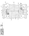
- Fig. 3 is a side, sectional view of the connector assembly taken along line 3-3 in Fig. 1.
-
- Referring now to the drawings, and particularly to Fig. 1, there is shown a portion of an
internal combustion engine 10 which includes ahousing 12 and a segmentedcamshaft assembly 14.Internal combustion engine 10 also includes other components, such as a crankshaft, a plurality of cylinders and a plurality of pistons reciprocally disposed within the cylinders (not shown). -
Housing 12 typically is of cast construction, and includes a plurality of bearing supports 16 that support respective optional steel backed aluminumfull round bearings 17. Eachbearing support 16 includes a substantially circularinterior bearing surface 38 for carryingcamshaft assembly 14. - Segmented
camshaft assembly 14 is rotatably carried byhousing 12, as indicated above. Segmentedcamshaft assembly 14 includes twocamshafts internal combustion engine 10, more than two camshafts may be provided. Camshaft 18 includes anend 22 which is attached with and carries agear 24.Gear 24 emmeshes with other suitable gears to rotatably drivecamshaft assembly 14. For example,gear 24 may be directly or indirectly emmeshed with a gear on the end of a crankshaft (not shown). - For ease of illustration, only
camshaft 18 will be described in detail hereinafter. However, the configuration ofcamshaft 20 is similar to that ofcamshaft 18, except for differences which will be noted. Camshaft 18 includes a plurality ofcam sets cam lobes cam lobe 30 is associated with a combustion air intake valve (not shown); eachcam lobe 34 is associated with an exhaust valve (not shown); and eachcam lobe 32 is associated with a fuel injector (not shown). Ifhousing 12 includes a "V" configuration with a first bank of combustion cylinders on one side and another bank of cylinders on another side, eachcam set 26 may be associated with a corresponding cylinder in one bank of cylinders; and eachcam set 28 may be associated with a cylinder in the other bank of cylinders. -
Cam sets camshaft 18. Between each axially adjacent pair ofcam sets camshaft 18 also includes acylindrical bearing 36 which is disposed within and rotatably carried by a corresponding cylindrical interior bearingsurface 38 of abearing 17. Camshaft 18 is thus intermittently rotatably supported along the length thereof byhousing 12. - With conventional segmented camshaft assemblies,
camshafts housing 12 for the bolted flange connection betweencamshafts combustion engine 10, which may be undesirable. - According to an aspect of the present invention,
camshafts connector assembly 40 which is disposed radially within a cylindrical bearingsurface 38 of abearing 17 carried byhousing 12. Thus,connector assembly 40 provides the dual functionality of connectingcamshafts bearing 17 ofhousing 12. By combining the connector and bearing functions together, the overall length ofinternal combustion engine 10 is reduced. -
Connector assembly 40 generally includes afirst flange 42 oncamshaft 20 and asecond flange 44 oncamshaft 18.First flange 42 includes an axially extendingrecess 46 defining anend face 48 against whichsecond flange 44 abuts.Second flange 44 includes an outside diameter which is received withinrecess 46 and used to axially aligncamshaft 18 andcamshaft 20, and includes anend face 50 which abuts againstend face 48. Each of end faces 48 and 50 include an axially extendinghole alignment dowel 56 is disposed withinholes camshafts -
First flange 42 andsecond flange 44 each include a plurality ofbolt holes second flange 44 is received withinrecess 46 offirst flange 42, andalignment dowel 56 is positioned within each of keyed alignment holes 52 and 54. A plurality ofbolts 62 are disposed within bolt holes 58 and 60 and connectfirst flange 42 together withsecond flange 44. - Each of
bolts 62 includes ahead 64 and an opposite threadedend 66.Bolts 62 may be placed within bolt holes 58 and 60 from one or both directions, depending upon the orientation of acam lobe first flange 42 andsecond flange 44. That is, the lobe portion of a cam lobe may not allow abolt 62 to be inserted from a particular axial direction. Thus, bolt 62 may be placed within bolt holes 56 and 58 in either selected axial direction. - To allow
bolt 62 to be placed within bolt holes 58 and 60 from either direction, a plurality of keeper blocks 68 may be selectively positioned againstfirst flange 42 orsecond flange 44, depending upon the axial directional orientation ofbolts 62. Eachkeeper block 68 includes at least one threadedbolt hole 70 therein. Eachkeeper block 68 has an arcuate shape which corresponds to the pattern of bolt holes 58 and 60 andfirst flange 42 andsecond flange 44, such that the threaded bolt holes 70 inkeeper block 68 align withbolt holes keeper block 68 includes two threaded bolt holes 70 therein. Some of keeper blocks 68 are disposed adjacent tofirst flange 42, while others of keeper blocks 68 are disposed adjacent tosecond flange 44. - To assemble
segmented camshaft assembly 14, eachcamshaft housing 12.Dowel 56 is placed within one ofholes second flange 44 is positioned withinfirst flange 42.First flange 42 andsecond flange 44 are preferably assembled with each other at a location between two bearingsupports 16 for ease of assembly.Bolts 62 are placed through each pair of corresponding bolt holes 58 and 60 and threaded into an associatedkeeper block 68. Camshafts 18 and 20 are then slid in an assembled state in an axial direction such that the assembledconnector assembly 40 is positioned within acylindrical bearing surface 38 of abearing 17. The outside cylindrical surface offirst flange 42 is rotatably carried by and within an associatedbearing 36. - In the method of assembly as described above,
camshafts housing 12 and then assembled together usingconnector assembly 40. It may also be possible to first assemblecamshafts connector assembly 40, and thereafter slidecamshafts housing 12 in an assembled state. - During use,
connector assembly 40 ofcamshaft assembly 14 provides the dual functionality of connectingcamshafts surface 36 disposed within abearing 17.Connector assembly 40 thereby allowscamshafts internal combustion engine 10. Additionally, the keyed alignment betweencamshafts bolts 62 to be inserted from either axial direction into bolt holes 58 and 60, and are configured to be engaged with eitherfirst flange 42 orsecond flange 44. - Other aspects, objects and advantages of this invention can be obtained from a study of the drawings, the disclosure and the appended claims.
- An internal combustion engine (10), comprising:
- a housing (12) including a plurality of bearing supports (16), each said bearing support (16) having a substantially cylindrical interior bearing surface (38); and
- a segmented camshaft assembly (14) including at least two camshafts (18, 20) axially adjacent to each other to define at least one adjacent pair of said camshafts (18, 20), each said camshaft (18, 20) being rotatably carried by said housing (12) and including a plurality of cam lobes (30, 32, 34), said camshaft assembly (14) including at least one connector assembly (40), each said connector assembly (40) connecting an adjacent said pair of camshafts (18, 20) together, each said connector assembly (40) having an exterior bearing surface (36) disposed within and rotatably carried by a corresponding said interior bearing surface (38) in said housing (12).
-
- The internal combustion engine (10), wherein preferably each said connector assembly (40) includes a first flange (42) on one of said adjacent pair of camshafts (18, 20) and a second flange (44) on an other of said adjacent pair of camshafts (18, 20).
- The internal combustion engine (10), wherein preferably said first flange (42) includes an axially extending recess (46) and said second flange (44) is disposed in said recess (46).
- The internal combustion engine (10), and/or wherein preferably said first flange (42) includes said exterior bearing surface (36).
- The internal combustion engine (10), and/or wherein preferably each of said first flange (42) and said second flange (44) include a plurality of bolt holes (58, 60), said bolt holes (58) in said first flange (42) substantially axially aligning with said bolt holes (60) in said second flange (44), and further comprising a plurality of bolts (62) disposed in said bolt holes (58, 60) and connecting said first flange (42) and said second flange (44) together.
- The internal combustion engine (10), and/or wherein preferably each of said bolts (62) includes a head (64) and an opposite threaded end (66), each said bolt head (64) disposed against a corresponding one of said flanges (42, 44) and each said threaded end (66) extending from a corresponding other of said flanges (42, 44), and further comprising a plurality of keeper blocks (68), each said keeper block (68) associated with at least one of said bolts (62) and disposed against said corresponding other flange (42, 44), each said keeper block (68) including at least one threaded bolt hole (70) engaged with said threaded end (66) of said at least one associated bolt (62).
- The internal combustion engine (10), and/or wherein preferably at least one of said keeper blocks (68) is disposed against said first flange (42) and at least one other of said keeper blocks (66) is disposed against said second flange (44).
- The internal combustion engine (10), and/or wherein preferably one of said first flange (42) and said second flange (44) includes an end face (48, 50) with an axially extending hole (52, 54), and further including an alignment dowel (56) extending from an other of said first flange (42) and said second flange (44), said dowel (56) received within said hole (52, 54), said dowel (56) and said hole (52, 54) providing keyed rotational alignment between said adjacent pair of camshafts (18, 20).
- The internal combustion engine (10), and/or wherein preferably said other of said first flange (42) and said second flange (44) includes an end face (48) with and axially extending hole (52, 54), and wherein said dowel (56) is disposed in each of said holes (52, 54).
- An internal combustion engine (10), comprising:
- a housing (12) including a plurality of bearing supports (16), each said bearing support (16) having an interior bearing surface (38); and
- a segmented camshaft assembly (14) including at least two camshafts (18, 20) axially adjacent to each other to define at least one adjacent pair of said camshafts (18, 20), each said camshaft (18, 20) being rotatably carried by said housing (12) and including a plurality of cam lobes (30, 32, 34), said camshaft assembly (14) including at least one connector assembly (40), each said connector assembly (40) connecting an adjacent said pair of camshafts (18, 20) together, each said connector assembly (40) including a first flange (42) on one of said adjacent pair of camshafts (18, 20) and a second flange (44) on an other of said adjacent pair of camshafts (18, 20), said first flange (42) including an axially extending recess (46) and said second flange (44) disposed in said recess (46), said first flange (42) having an exterior bearing surface (36) disposed within and rotatably carried by a corresponding said interior bearing surface (38) in said housing (12).
-
- The internal combustion engine (10), and/or wherein preferably each of said first flange (42) and said second flange (44) include a plurality of bolt holes (58, 60), said bolt holes (58, 60) in said first flange (42) substantially axially aligning with said bolt holes (58, 60) in said second flange (44), and further comprising a plurality of bolts (62) disposed in said bolt holes (58, 60) and connecting said first flange (42) and said second flange (44) together.
- The internal combustion engine (10), and/or wherein preferably each of said bolts (62) includes a head (64) and an opposite threaded end (66), each said bolt head (64) disposed against a corresponding one of said flanges (42, 44) and each said threaded end (66) extending from a corresponding other of said flanges (42, 44), and further comprising a plurality of keeper blocks (68), each said keeper block (68) associated with at least one of said bolts (62) and disposed against said corresponding other flange, each said keeper block (66) including at least one threaded bolt hole (70) engaged with said threaded end (66) of said at least one associated bolt (62).
- The internal combustion engine (10), and/or wherein preferably at least one of said keeper blocks (66) is disposed against said first flange (42) and at least one other of said keeper blocks (68) is disposed against said second flange (44).
- The internal combustion engine (10), and/or wherein preferably one of said first flange (42) and said second flange (44) includes an end face (48) with an axially extending hole (52, 54), and further including an alignment dowel (56) extending from an other of said first flange (42) and said second flange (44), said dowel (56) received within said hole (52, 54), said dowel (56) and said hole (52, 54) providing keyed rotational alignment between said adjacent pair of camshafts (18, 20).
- The internal combustion engine (10), and/or wherein preferably said other of said first flange (42) and said second flange (44) includes an end face (48) with and axially extending hole (52, 54), and wherein said dowel (56) is disposed in each of said holes (52, 54).
- The internal combustion engine (10), and/or wherein preferably said bearing support (16) includes a steel backed aluminum bearing (17) defining said interior bearing surface (38).
- In its broadest aspect the inventions relates to an internal combustion engine (10), comprising: a housing (12); and a camshaft assembly (14) including at least two camshafts (18, 20), each said camshaft (18, 20) including a plurality of cam lobes (30, 32, 34), said camshaft assembly (14) including at least one connector assembly (40), said connector assembly (40) connecting a pair of camshafts (18, 20) together.
Claims (10)
- An internal combustion engine (10), comprising:a housing (12) including a plurality of bearing supports (16), each said bearing support (16) having a substantially cylindrical interior bearing surface (38); anda segmented camshaft assembly (14) including at least two camshafts (18, 20) axially adjacent to each other to define at least one adjacent pair of said camshafts (18, 20), each said camshaft (18, 20) being rotatably carried by said housing (12) and including a plurality of cam lobes (30, 32, 34), said camshaft assembly (14) including at least one connector assembly (40), each said connector assembly (40) connecting an adjacent said pair of camshafts (18, 20) together, each said connector assembly (40) having an exterior bearing surface (36) disposed within and rotatably carried by a corresponding said interior bearing surface (38) in said housing (12).
- The internal combustion engine (10) of claim 1, wherein each said connector assembly (40) includes a first flange (42) on one of said adjacent pair of camshafts (18, 20) and a second flange (44) on an other of said adjacent pair of camshafts (18, 20).
- The internal combustion engine (10) of claim 2, wherein said first flange (42) includes an axially extending recess (46) and said second flange (44) is disposed in said recess (46).
- The internal combustion engine (10) of claim 3, wherein said first flange (42) includes said exterior bearing surface (36).
- The internal combustion engine (10) of claim 3, wherein each of said first flange (42) and said second flange (44) include a plurality of bolt holes (58, 60), said bolt holes (58) in said first flange (42) substantially axially aligning with said bolt holes (60) in said second flange (44), and further comprising a plurality of bolts (62) disposed in said bolt holes (58, 60) and connecting said first flange (42) and said second flange (44) together.
- The internal combustion engine (10) of claim 5, wherein each of said bolts (62) includes a head (64) and an opposite threaded end (66), each said bolt head (64) disposed against a corresponding one of said flanges (42, 44) and each said threaded end (66) extending from a corresponding other of said flanges (42, 44), and further comprising a plurality of keeper blocks (68), each said keeper block (68) associated with at least one of said bolts (62) and disposed against said corresponding other flange (42, 44), each said keeper block (68) including at least one threaded bolt hole (70) engaged with said threaded end (66) of said at least one associated bolt (62).
- The internal combustion engine (10) of any of the preceding claims, wherein at least one of said keeper blocks (68) is disposed against said first flange (42) and at least one other of said keeper blocks (66) is disposed against said second flange (44), one of said first flange (42) and said second flange (44) includes an end face (48, 50) with an axially extending hole (52, 54), and further including an alignment dowel (56) extending from an other of said first flange (42) and said second flange (44), said dowel (56) received within said hole (52, 54), said dowel (56) and said hole (52, 54) providing keyed rotational alignment between said adjacent pair of camshafts (18, 20), said other of said first flange (42) and said second flange (44) includes an end face (48) with and axially extending hole (52, 54), and wherein said dowel (56) is disposed in each of said holes (52, 54).
- An internal combustion engine (10), comprising:a housing (12) including a plurality of bearing supports (16), each said bearing support (16) having an interior bearing surface (38); anda segmented camshaft assembly (14) including at least two camshafts (18, 20) axially adjacent to each other to define at least one adjacent pair of said camshafts (18, 20), each said camshaft (18, 20) being rotatably carried by said housing (12) and including a plurality of cam lobes (30, 32, 34), said camshaft assembly (14) including at least one connector assembly (40), each said connector assembly (40) connecting an adjacent said pair of camshafts (18, 20) together, each said connector assembly (40) including a first flange (42) on one of said adjacent pair of camshafts (18, 20) and a second flange (44) on an other of said adjacent pair of camshafts (18, 20), said first flange (42) including an axially extending recess (46) and said second flange (44) disposed in said recess (46), said first flange (42) having an exterior bearing surface (36) disposed within and rotatably carried by a corresponding said interior bearing surface (38) in said housing (12).
- The internal combustion engine (10) of any of the preceding claims, wherein each of said first flange (42) and said second flange (44) include a plurality of bolt holes (58, 60), said bolt holes (58, 60) in said first flange (42) substantially axially aligning with said bolt holes (58, 60) in said second flange (44), and further comprising a plurality of bolts (62) disposed in said bolt holes (58, 60) and connecting said first flange (42) and said second flange (44) together, and/or wherein preferably each of said bolts (62) includes a head (64) and an opposite threaded end (66), each said bolt head (64) disposed against a corresponding one of said flanges (42, 44) and each said threaded end (66) extending from a corresponding other of said flanges (42, 44), and further comprising a plurality of keeper blocks (68), each said keeper block (68) associated with at least one of said bolts (62) and disposed against said corresponding other flange, each said keeper block (66) including at least one threaded bolt hole (70) engaged with said threaded end (66) of said at least one associated bolt (62), and/or wherein preferably at least one of said keeper blocks (66) is disposed against said first flange (42) and at least one other of said keeper blocks (68) is disposed against said second flange (44), and/or wherein preferably one of said first flange (42) and said second flange (44) includes an end face (48) with an axially extending hole (52, 54), and further including an alignment dowel (56) extending from an other of said first flange (42) and said second flange (44), said dowel (56) received within said hole (52, 54), said dowel (56) and said hole (52, 54) providing keyed rotational alignment between said adjacent pair of camshafts (18, 20), and/or wherein preferably said other of said first flange (42) and said second flange (44) includes an end face (48) with and axially extending hole (52, 54), and wherein said dowel (56) is disposed in each of said holes (52, 54), and/or wherein preferably said bearing support (16) includes a steel backed aluminum bearing (17) defining said interior bearing surface (38).
- An internal combustion engine (10), comprising:a housing (12); anda camshaft assembly (14) including at least two camshafts (18, 20), each said camshaft (18, 20) including a plurality of cam lobes (30, 32, 34), said camshaft assembly (14) including at least one connector assembly (40), said connector assembly (40) connecting a pair of camshafts (18, 20) together.
Applications Claiming Priority (2)
| Application Number | Priority Date | Filing Date | Title |
|---|---|---|---|
| US09/325,989 US6182627B1 (en) | 1999-06-04 | 1999-06-04 | Segmented camshaft assembly for an internal combustion engine |
| US325989 | 2002-12-19 |
Publications (2)
| Publication Number | Publication Date |
|---|---|
| EP1057979A2 true EP1057979A2 (en) | 2000-12-06 |
| EP1057979A3 EP1057979A3 (en) | 2002-11-27 |
Family
ID=23270336
Family Applications (1)
| Application Number | Title | Priority Date | Filing Date |
|---|---|---|---|
| EP00112094A Withdrawn EP1057979A3 (en) | 1999-06-04 | 2000-06-05 | Segmented camshaft assembly for an internal combustion engine |
Country Status (2)
| Country | Link |
|---|---|
| US (1) | US6182627B1 (en) |
| EP (1) | EP1057979A3 (en) |
Cited By (3)
| Publication number | Priority date | Publication date | Assignee | Title |
|---|---|---|---|---|
| WO2005090756A1 (en) * | 2004-02-23 | 2005-09-29 | Tyssenkrupp Automotive Ag | Built multiple cam |
| US20130269474A1 (en) * | 2010-05-11 | 2013-10-17 | Agap Hb | Camshaft with detachable bearing journals |
| WO2021197563A1 (en) * | 2020-03-30 | 2021-10-07 | Wärtsilä Finland Oy | A camshaft assembly for an internal combustion piston engine and a method of assembling a camshaft assembly into an engine block |
Families Citing this family (4)
| Publication number | Priority date | Publication date | Assignee | Title |
|---|---|---|---|---|
| US8147226B2 (en) * | 2006-02-01 | 2012-04-03 | Black & Decker Inc. | Valve assembly for pressure washer pump |
| US7895982B2 (en) * | 2007-12-18 | 2011-03-01 | Caterpillar Inc. | Refurbished camshaft and method |
| US7895743B2 (en) * | 2007-12-18 | 2011-03-01 | Caterpillar Inc. | Refurbished camshaft and method |
| CN110388242B (en) * | 2019-07-12 | 2023-09-15 | 长沙光华航空科技有限公司 | Engine |
Family Cites Families (8)
| Publication number | Priority date | Publication date | Assignee | Title |
|---|---|---|---|---|
| JPS612970A (en) * | 1984-06-18 | 1986-01-08 | Ngk Insulators Ltd | Engine camshaft |
| IT9020789A1 (en) * | 1989-07-04 | 1991-01-05 | Gkn Automotive Ag | CAMSHAFT |
| US5287840A (en) | 1992-07-30 | 1994-02-22 | General Electric Canada Inc. | Cam sections for a "V"-type diesel engine |
| US5664463A (en) * | 1993-03-03 | 1997-09-09 | Amborn; Peter | Camshaft assembly with shaft elements positioned one inside the other and method of producing same |
| DE4434982A1 (en) * | 1994-09-30 | 1996-04-04 | Mak Maschinenbau Krupp | camshaft |
| DE19606732C2 (en) * | 1995-02-27 | 2001-11-08 | Emitec Emissionstechnologie | Joined multilayer waves |
| US5826461A (en) * | 1996-01-22 | 1998-10-27 | Kaywood Products Corporation | Camshaft assembly and method of making the same |
| US5778841A (en) | 1997-02-26 | 1998-07-14 | Cummins Engine Company, Inc. | Camshaft for internal combustion engines |
-
1999
- 1999-06-04 US US09/325,989 patent/US6182627B1/en not_active Expired - Fee Related
-
2000
- 2000-06-05 EP EP00112094A patent/EP1057979A3/en not_active Withdrawn
Non-Patent Citations (1)
| Title |
|---|
| None |
Cited By (6)
| Publication number | Priority date | Publication date | Assignee | Title |
|---|---|---|---|---|
| WO2005090756A1 (en) * | 2004-02-23 | 2005-09-29 | Tyssenkrupp Automotive Ag | Built multiple cam |
| US7305953B2 (en) | 2004-02-23 | 2007-12-11 | Thyssenkrupp Automotive Ag | Built multiple cam |
| CN100436759C (en) * | 2004-02-23 | 2008-11-26 | 泰森克鲁普普里斯塔技术中心股份公司 | Assembled multi-way cam |
| US20130269474A1 (en) * | 2010-05-11 | 2013-10-17 | Agap Hb | Camshaft with detachable bearing journals |
| US10494959B2 (en) * | 2010-05-11 | 2019-12-03 | Agap Hb | Camshaft with detachable bearing journals |
| WO2021197563A1 (en) * | 2020-03-30 | 2021-10-07 | Wärtsilä Finland Oy | A camshaft assembly for an internal combustion piston engine and a method of assembling a camshaft assembly into an engine block |
Also Published As
| Publication number | Publication date |
|---|---|
| US6182627B1 (en) | 2001-02-06 |
| EP1057979A3 (en) | 2002-11-27 |
Similar Documents
| Publication | Publication Date | Title |
|---|---|---|
| US8800517B2 (en) | Cam shaft/cam gear assembly and thrust strategy for engine using same | |
| US6182627B1 (en) | Segmented camshaft assembly for an internal combustion engine | |
| US4787342A (en) | V-6 engine | |
| US20110220055A1 (en) | Modular engine assembly and fluid control assembly for hydraulically-actuated mechanism | |
| US7082916B2 (en) | Valve spring support structure of engine | |
| JP2021001604A (en) | Sealing device modular type rotary valve device and engine | |
| EP1384859B1 (en) | Engine | |
| US6560867B2 (en) | Modular valvetrain and cylinder head structure | |
| US6543401B2 (en) | Camshaft drive mechanism | |
| US8651075B2 (en) | Engine assembly including camshaft with independent cam phasing | |
| EP2194240A1 (en) | Camshaft speed sensor target | |
| US7600493B2 (en) | Spline drive and cam shafts for barrel engines | |
| JP2000087824A (en) | Radial piston pump | |
| CN102251822A (en) | Engine assembly with camshaft housing | |
| EP0971116B1 (en) | Internal combustion engine | |
| US6257187B1 (en) | Pivot shaft for an internal combustion engine | |
| JP3545146B2 (en) | Assembly type camshaft connection structure | |
| EP1995500B1 (en) | Cylinder head gasket for an internal combustion engine | |
| JPH108987A (en) | Chain cover structure for 4-cycle engine | |
| JP3275773B2 (en) | Engine cam cap structure | |
| JP2516760B2 (en) | Spark plug attachment device in engine | |
| JPH09264225A (en) | Fuel injection structure of direct injection engine | |
| US20050145210A1 (en) | Engine and crank housing | |
| WO2015171338A1 (en) | Coupler system and camshaft phaser system incorporating the same | |
| JP2008075501A (en) | Multiple crankshaft engine |
Legal Events
| Date | Code | Title | Description |
|---|---|---|---|
| PUAI | Public reference made under article 153(3) epc to a published international application that has entered the european phase |
Free format text: ORIGINAL CODE: 0009012 |
|
| AK | Designated contracting states |
Kind code of ref document: A2 Designated state(s): AT BE CH CY DE DK ES FI FR GB GR IE IT LI LU MC NL PT SE |
|
| AX | Request for extension of the european patent |
Free format text: AL;LT;LV;MK;RO;SI |
|
| PUAL | Search report despatched |
Free format text: ORIGINAL CODE: 0009013 |
|
| AK | Designated contracting states |
Kind code of ref document: A3 Designated state(s): AT BE CH CY DE DK ES FI FR GB GR IE IT LI LU MC NL PT SE |
|
| AX | Request for extension of the european patent |
Free format text: AL;LT;LV;MK;RO;SI |
|
| AKX | Designation fees paid | ||
| REG | Reference to a national code |
Ref country code: DE Ref legal event code: 8566 |
|
| STAA | Information on the status of an ep patent application or granted ep patent |
Free format text: STATUS: THE APPLICATION IS DEEMED TO BE WITHDRAWN |
|
| 18D | Application deemed to be withdrawn |
Effective date: 20030528 |