EP1057652A2 - Printer and charging device - Google Patents
Printer and charging device Download PDFInfo
- Publication number
- EP1057652A2 EP1057652A2 EP00304308A EP00304308A EP1057652A2 EP 1057652 A2 EP1057652 A2 EP 1057652A2 EP 00304308 A EP00304308 A EP 00304308A EP 00304308 A EP00304308 A EP 00304308A EP 1057652 A2 EP1057652 A2 EP 1057652A2
- Authority
- EP
- European Patent Office
- Prior art keywords
- power supply
- supply unit
- main power
- printer
- backup
- Prior art date
- Legal status (The legal status is an assumption and is not a legal conclusion. Google has not performed a legal analysis and makes no representation as to the accuracy of the status listed.)
- Granted
Links
- 239000003990 capacitor Substances 0.000 claims description 37
- 238000000034 method Methods 0.000 description 20
- 238000010586 diagram Methods 0.000 description 11
- 230000010355 oscillation Effects 0.000 description 5
- 229910003307 Ni-Cd Inorganic materials 0.000 description 1
- 238000007596 consolidation process Methods 0.000 description 1
- 238000007599 discharging Methods 0.000 description 1
- PCHJSUWPFVWCPO-UHFFFAOYSA-N gold Chemical compound [Au] PCHJSUWPFVWCPO-UHFFFAOYSA-N 0.000 description 1
- 239000010931 gold Substances 0.000 description 1
- 229910052737 gold Inorganic materials 0.000 description 1
- 238000012423 maintenance Methods 0.000 description 1
- 238000005457 optimization Methods 0.000 description 1
- 238000005086 pumping Methods 0.000 description 1
- 230000000452 restraining effect Effects 0.000 description 1
- 239000007921 spray Substances 0.000 description 1
Images


Classifications
-
- B—PERFORMING OPERATIONS; TRANSPORTING
- B41—PRINTING; LINING MACHINES; TYPEWRITERS; STAMPS
- B41J—TYPEWRITERS; SELECTIVE PRINTING MECHANISMS, i.e. MECHANISMS PRINTING OTHERWISE THAN FROM A FORME; CORRECTION OF TYPOGRAPHICAL ERRORS
- B41J29/00—Details of, or accessories for, typewriters or selective printing mechanisms not otherwise provided for
- B41J29/38—Drives, motors, controls or automatic cut-off devices for the entire printing mechanism
- B41J29/393—Devices for controlling or analysing the entire machine ; Controlling or analysing mechanical parameters involving printing of test patterns
Definitions
- the present invention relates to a printer and a charging device of a backup power supply for the printer. Especially, the present invention relates to a charging system of the backup power supply such as a rechargeable battery for supplying power to a Real Time Clock IC and the like in the printer.
- a switching regulator is generally used as the main power supply of the ink jet printer.
- the switching regulator of the ink jet printer oscillates intermittently at voltage wave with low duty ratio while the main switch is OFF.
- CPU and the like monitor the state of the main switch provided to the secondary side of the power supply.
- the main switch is turned off, the CPU allows the capping process of the print head to perform, and then sends a prescribed signal to the main power supply.
- the main power supply receives the signal from the CPU and transits to the above-mentioned intermittent oscillation state.
- the printer and the like it is necessary for the printer and the like to perform a backup operation for a memory, when the main power supply is turned off.
- the backup operation operational information of the printer is recorded to the memory such as an EEPROM.
- the ink jet printer has a Real Time Clock IC, which is hereinafter called as RTC.
- the RTC is used to perform several types of pumping operation for adjusting the suction amount of the ink in accordance with the length of unused time and to print printing time to ends of print papers based on unique commands from a host computer.
- the RTC is a digital IC which outputs current time, for example, xx(hour) xx(minute) xx (second) on xx(month) xx(day), xx(year).
- the ink jet printer has to supply power to the RTC, even if the main switch is OFF.
- electric apparatuses such as the printer is provided with an electric double layer capacitor or a rechargeable battery as a backup power supply.
- the backup power supply is charged while the main power supply is ON, and continuously drives the RTC or performs the backup operation for the memory by using the charged power when the main switch is turned off.
- the RTC in the printer is continuously driven.
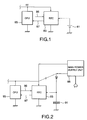
- a first example has the rechargeable battery such as a Lie battery or a Ni-Cd battery in the printer, and allows the RTC to drive by using power that the rechargeable battery discharged.
- a printer of the first example is provided with a Li battery 81 as shown in Fig. 1.
- a RTC 83 is driven by the power supplied constantly from the Li battery 81.
- the RTC 83 outputs a digital signal 87 showing the current time to a CPU 85 when a prescribed signal 86 is inputted from the CPU 85.
- a printer of a second example, as shown in Fig. 2 has a high performance capacitor, which is called a super capacitor, a gold capacitor, electric double layer capacitor, or the like.
- the capacitor is charged while the main switch of the printer is ON, and the RTC is continuously driven by electric charge charged to the capacitor when the main switch of the printer is turned off.
- the RTC 93 is driven by the power supplied from the main power supply 98. While the main supply is ON, the capacitor 91 is charged by the power supplied from the main power supply 98. The main switch of the printer is turned off, and the RTC 93 is continuously driven by the electric charge charged to the capacitor 91. Similarly to the first example, when a prescribed signal 96 is inputted from the CPU 95, the RTC 93 outputs to the CPU 95 a digital signal 97 indicating the current time.
- a first object of the present invention is to provide a printer having a backup power supply and a charging device which can realize low price and low power consumption, without using a primary battery impossible to recharge.
- a second object of the present invention is to provide a printer and a charging device which can realize low power consumption by restraining the charging time to the shortest time.
- a printer comprising:
- a printer comprising:
- Futhermore a charging device of a backup power supply for a printer which can supply power for performing a prescribed backup operation to the printer having a main power supply unit capable of taking at least two states of ON state and a prescribed sleep state when a main power supply unit is not in ON state, and which can perform charge/discharge comprising
- Futhermore a printer comprising:
- Futhermore a charging device of a backup power supply for a printer which can supply power for performing a prescribed backup operation to the printer having a main power supply unit capable of taking at least two states of ON state and a prescribed sleep state when a main power supply unit is not in ON state, and which can perform charge/discharge comprising:
- the present invention for example, even if the main switch is turned off by user, it is possible to safely perform a prescribed backup operation, to reduce use of components such as a primary battery undesirable for environment, and to realize low cost and low power consumption. Furthermore, it is possible to realize the charging device of the backup power supply for supplying power to perform a prescribed backup operation for the printer by a simplified configuration. Accordingly, the industrial value of the present invention is very large. Furthermore, because the present invention controls the ON period of the main switch based on hysteretic information, it is possible to shorten charging time and to reduce power consumption.
- the ink jet printer has a printer controller 2, a print engine 4, a main power supply unit 6, and a RTC unit 8.
- the printer controller 2 has a CPU 10, a ROM 12, a RAM 14, an EEPROM 16, a mechanic interface block (mechanic I/F) 18, and a host interface block 20. These are connected to each other via a bus 22.
- the print engine 4 has a print head 42, a carriage mechanism consisted of a carriage 43 and the like, a paper feeder mechanism consisted of a paper feeder (PF) motor 44 and the like.
- the paper feeder mechanism has the PF motor and a paper feeder roller (unshown), and sends out a print recording medium such as a recording paper 45 in order to scan the print head 42 in sub scanning direction.
- the carriage mechanism has a carriage 43 for mounting the print head 42 and a carriage (CR) motor 43a for allowing the carriage 43 to run via a timing belt and the like, in order to scan the print head 42 in main scanning direction.
- the print head 42 spits out fine ink dews by using a piezoelectric element.
- the carriage 43 returns to home position in a prescribed case, in order to perform various maintenance for the print head 42. For example, when cutting off the power, at the state the carriage 43 has returned to the home position, a capping process is performed. In this capping process, an ink spray portion is capped.
- the main power supply unit 6 has a switching regulator (unshown) and the like.
- the main power supply unit 6 is supplied with alternating power from commercial power supply (unshown).
- the main power supply unit 6 supplies 42V to the print head 42 of the print engine 4 and the like, and 5.0V or 3.3V to the printer controller 2.
- the main power supply unit 6 is connected to a panel switch 5 provided to the printer panel.
- the panel switch 5 outputs ON/OFF signals alternatively by each time when user operates the panel switch 5.
- An ON switch and an OFF switch are separately provided to the panel switch 5.
- the main power supply unit 6 is turned on/off by receiving the signal from the panel switch 5. Even if the panel switch 5 is turned off, as long as the power supply plug 32 is not pulled out, the main power supply unit 6 enters a prescribed sleep state.
- the prescribed sleep state means that the panel switch 5 is turned off, the supply of the power to the printer mechanism such as the printer engine is cut off, a little power is supplied to CPU 10 and the like.
- the main power supply oscillates intermittently, as described above.
- the RTC unit 8 has a RTC 34 and a backup power supply 36.
- the backup power supply 36 has a rechargeable battery 36a and a diode 36b, and acts when the main power supply unit 6 is OFF.
- the RTC 34 continuously acts by power supplied from the backup power supply 36, even while the main power supply unit 6 is cut off.
- the RTC 34 outputs a digital signal 34a indicating the current time to a CPU 10 when a prescribed signal 10a is supplied from the CPU 10.
- a first event is an event in case that the voltage of the backup power supply 36 becomes low.
- a second event is an event in case that a prescribed time passes off after entering the sleep state.
- Fig. 4 is a block diagram showing schematic configuration of a first embodiment relating to a charging device of a backup power supply.
- the charging device of the first embodiment has a feature in which the main power supply unit 6 is turned on by a signal from the RTC 34 by using the above-mentioned first event as a trigger, and then the rechargeable battery 36a is continuously charged during required minimum supplementary charging time necessary to complete the charge for the rechargeable battery 36a, and then the main power supply unit 6 returns again to a intermittent oscillation state.
- the charging device of the first embodiment has a main power supply unit (PS) 6, a CPU 10, a RTC 34, a first switch 37, and a second switch 38.
- the main power supply 6, for example, supplies 42V to a printer driver such as a printer engine 4 and a secondary voltage of 5.0V or 3.3V to a logic circuit such as a printer controller 2.
- the CPU 10 checks the state of the panel switch 5 of the printer. When the main power supply unit 6 is turned on from the sleep mode, the CPU 10 performs various control operations depending on whether the power ON depends on the panel switch 5 or the RTC 34.
- the RTC 34 of the present embodiment has a timer 34B and a comparator 34C.
- the comparator 34C checks the output voltage of the rechargeable voltage 36a.
- the comparator 34C compares the output voltage of the rechargeable battery 36a with a prescribed reference voltage RefV which is, for example, (1.5V+ ).
- the RTC 34 When the comparator 34C determines that the output voltage of the rechargeable battery 36a underruns the reference voltage RefV, the RTC 34 outputs a power ON signal 34d, sets the second switch 38 to ON, and returns the main power supply unit 6 to ON state.
- the power ON signal 34d is outputted, for example, for 3 minutes, and the main power supply unit 6 is set to ON only during 3 minutes.
- the timer 34B counts during 3 minutes as a prescribed supplementary charging time.
- the first switch 37 has the panel switch 5 of the printer shown in Fig. 3 and another switch 37a which opens and shuts simultaneously working with the panel switch 5.
- the panel switch 5 When the panel switch 5 is in OFF, as long as the outlet is not pull out, the main power supply unit 6 transits to the intermittent oscillation state. After then, if the panel switch 5 is turned on, the main power supply unit 6 returns to state for outputting a normal secondary voltage.
- the switch 37a When the panel switch 5 is turned on/off, the switch 37a opens or shuts simultaneously working with the panel switch 5. Because of this, as shown in Fig. 4, the signal 37b for transmitting ON/OFF of the panel switch 5 is outputted, and is transmitted to the CPU 10.
- Fig. 5 is a flowchart showing processes and operations of the charging device according to the present embodiment.
- the processes and operations of the charging device of Fig. 4 will be described.
- the printer enters the sleep mode (S301), thereby becoming the above-mentioned intermittent oscillating state.
- the sleeping mode for example, when the panel switch 5 is turned on by user, or when the main power supply unit 6 is turned on by a power ON signal 34d from the RTC 34 (S302), it is determined whether the power ON depends on the RTC 34 or the panel switch 5 (S303).
- the power ON state is continued for 3 minutes (S304).
- the charge for the rechargeable battery 36a is performed for 3 minutes.
- the main power supply unit 6 is turned off after 3 minutes.
- the panel switch 5 returns to OFF state.
- the CPU 10 always checks whether the panel switch 5 is turned on or not (S305). If the panel switch 5 keeps OFF state, the process of the step S301 is performed, thereby continuing the above-mentioned sleep mode.
- the CPU 10 checks whether or not the panel switch 5 is turned off (S306). If the panel switch 5 is turned off (Yes in step S306), the CPU 10 waits until the processes necessary to cut off the supply of power for the printer, for example, the capping process is completed.
- step S307 it is determined whether more than three minutes passed off (S308). If determined that more than three minutes passed off (Yes in S308), process of the step S301 is performed to continue the above-mentioned sleep mode.
- the CPU 10 waits while checking the panel switch 5 until the remaining time to three minutes passes off (S309). That is, the CPU 10 checks whether or not the panel switch 5 is turned off (S310), as long as the panel switch 5 is not turned off (No in step S310), the process of the step S306 is again performed. When the panel switch 5 is turned off (Yes in step S310), the process of the step S301 is again performed, thereby continuing the above-mentioned sleep mode.
- the charging device of the present embodiment during the sleeping mode (energy saving mode) in which the main power supply unit of the printer performs the intermittent oscillation, even if voltage of the rechargeable battery 36a becomes low, it is possible to automatically allow the main power supply unit 6 to transit to ON state, and to charge the rechargeable battery 36a by using the power supplied from the main power supply unit 6.
- a charging device of a second embodiment has a feature in which the above-mentioned second event is used as a trigger. That is, when becoming the intermittent oscillating state depending on the power OFF, by each of the constant period (supplementary charging interval time), the CPU generates a signal during a constant time (supplementary charging time). The main power unit 6 is turned on/off by the signal from the CPU.
- the charging device of the second embodiment has a third switch 39, as shown by a dotted line in Fig. 4.
- the third switch 39 is turned on by a prescribed supplementary charging signal 10h from the CPU 10.
- the main power supply unit 6 returns from the intermittent oscillating state to the state outputting the normal secondary voltage.
- the supplementary charging signal 10h is sent only for 3 minutes, for example, by 24 or 10 hours, during the intermittent oscillating state.
- the processes and the operations of the charging device according to the second embodiment is the same as that of the first embodiment, except that the CPU 10 performs the processes of steps S303 and S304 of Fig. 5. Because of this, detailed description relating to the processes and the operations of the second embodiment will be omitted.
- the CPU 10 may generate the above-mentioned signal based on the result of executing prescribed control instruction groups (program) stored in the ROM 12 with reference to time information from the RTC 34 or the timer 34B which may be provided in the CPU 10.
- a third embodiment uses an electric double layer capacitor as the backup power supply for allowing the above-mentioned RTC to continuously run during power OFF. Optimization of the charging time for the electric double layer capacitor is realized by managing and referring hysteretic information relating to voltage between ends of the electric double layer capacitor.
- the RTC and the electric double layer capacitor of the third embodiment is built in the ink jet printer, similarly to the first and second embodiments. Because the other configuration of the third embodiment is the same as that of the first and second embodiments, the detailed description will be omitted. First of all, a first example of control method using the hysteretic information according to the present embodiment will be described hereinafter.
- Fig. 6 is a diagram showing a change for time of voltage between ends of the electric double layer capacitor.
- the electric double layer capacitor is being already charged at state that the main power supply unit 6 is turned on as referred to 401, if the main power supply unit 6 is turned off as referred to 402, the voltage between ends of the electric double layer capacitor becomes low gradually, as shown in Fig. 6.
- a minimum voltage shown in Fig. 6 expresses a maximum voltage that operation of the RTC stops.
- the simplest example of the hysteretic control is the case that the main power supply unit 6 is turned on when voltage between ends of the electric double layer capacitor has lowered till the minimum voltage.
- the hysteretic information that operation of the RTC 34 stopped is obtained.
- zero is set. That is, the timer such as a CPU timer is set to zero, and the charging time Tch becomes full charge after 3 minutes pass off.
- the printer continues to run, and the main power supply unit 6 is turned off as an event at any time as shown in 406. In this case, it is unnecessary to charge further for 3 minutes. As shown in the same drawing, for example, when the event which is turned off on the condition of Tch 3 minutes occurs, this event means that it is unnecessary to maintain ON any longer. Accordingly, at this point when charge of the electric double layer capacitor finished, the discharge begins as shown in 406 and 413.
- Fig. 7 is a diagram showing change of voltage between ends of the electric double layer capacitor by charge/discharge.
- a horizontal axis of Fig. 7 is a time (t), and a vertical axis of Fig. 7 is the voltage (v) between ends of the electric double layer capacitor.
- Fig. 8 is a block diagram showing schematic configuration of a third embodiment of a charging device according to the present invention.
- the charging device of Fig. 8 has power supply unit 601, a CPU 602, an electric double layer capacitor 603 functioned as a backup power supply, and a RTC 604.
- the main power supply unit 601 Inside of the main power supply unit 601 is provided with a compact power supply 607 for detecting on/off condition of a switch 601a. When ON of the switch 601a is detected, the electric double layer capacitor 603 is charged, and the power is supplied to each part of the printer.
- the main power supply unit 601 begins the supply of the power by signal from the RTC 604.
- a voltage detecting section 604a for detecting the charging voltage of the electric double layer capacitor 603.
- a comparison determining section 602a for determining whether or not the charging voltage detected by the voltage detecting section 604a is lower than a prescribed reference voltage
- a charge indicating section 602b for allowing the main power supply unit 6 to turn on when determined to be low.
- the voltage detecting section 604a, the comparison determining section 602a, and the charge indicating section 602b correspond to hysteretic management means.
- the main power supply unit 6 begins the supply of the power not only in case the switch 601a is turned on, but also by the signal from the RTC 604.
- the CPU 602 restarts.
- the CPU 602 can detect the reason why the main power supply unit 601 has begun the supply of the power by receiving the signal from the RTC 604.
- the third embodiment detects the condition of the electric double layer capacitor based on time.
- the CPU 602 has to detect the above-mentioned minimum voltage and whether or not the RTC 604 stopped.
- the present invention is not limited certain embodiments described above, and is applicable to other embodiments in the range of Claims described after.
- the main power supply unit when the voltage of the backup power supply has lowered, by using the first event as the trigger, an example which turns on the main power supply unit based on the signal from the RTC and performs supplementary charge has been described.
- the main power supply unit when the prescribed time has passed off after entering the sleep state, by using the second event as the trigger, the main power supply unit is turned on by the signal from the CPU to perform supplementary charge.
- the main power supply unit in case that a prescribed time passed off after entering the sleep state, by using the second event as the trigger, the main power supply unit may be turned on by the signal from the RTC to perform supplementary charge.
- charging systems for allowing the RTC to continuously run when the main power supply unit 6 is not in ON state has been described.
- Objects that the rechargeable battery supplies the power are not limited.
- backup operation of the memory and the like may be performed by using the rechargeable battery.
- the backup power supply is required that it is possible to repeat charge/discharge and to supply the power for performing a prescribed backup operation when the main power supply unit 6 is not in ON state. If these requirement are filled, any besides the rechargeable battery and the electric double layer capacitor is applicable as the backup power supply.
- the printer has the charging device, and the charging device is constituted of the CPU in the printer, and the timer and the comparator in the RTC has been described.
- the charging device may be constituted as an external unit of the printer.
- the present invention has been described as an example of the ink jet printer for performing the capping.
- the present invention is also applicable to other printers such as a laser printer which has the main power supply unit with ON state and sleep state, and can repeat charge/discharge. That is, the present invention is applicable to any types of the printers which has the backup power supply for supplying the power to perform a prescribed backup operation when the main power supply unit is not ON state.
Landscapes
- Charge And Discharge Circuits For Batteries Or The Like (AREA)
- Accessory Devices And Overall Control Thereof (AREA)
- Electrical Discharge Machining, Electrochemical Machining, And Combined Machining (AREA)
- Photoreceptors In Electrophotography (AREA)
Abstract
Description
wherein said backup power supply is charged by using power of said main power supply unit when said main power supply unit is in ON state.
wherein said backup power supply is charged by using power of said main power supply unit when said main power supply unit is in ON state.
Claims (21)
- A printer comprising:a printer mechanism;a printer controller for controlling said printer mechanism;a main power supply unit for supplying power to said printer mechanism and said printer controller;a backup power supply capable of repeating charge/discharge for supplying power to perform a prescribed backup operation to said printer controller by discharge, and charging controller for allowing said main power supply unit to turn on by period necessary to charge said backup power supply and charging said backup power supply by using power of said main power supply unit when said main power supply unit is ON state.
- A printer comprising:a printer mechanism;a printer controller for controlling said printer mechanism;a main power supply unit capable of supplying power to said printer mechanism and said printer controller, and taking at least two states of ON state and sleep state;a backup power supply capable of repeating charge/discharge for supplying power to perform a prescribed backup operation to said printer controller by discharge, andcharging controller for tuning on said main power supply unit by a prescribed period when said main power supply unit is in the sleep state in order to charge said backup power supply by using power of said main power supply unit.
- The printer according to Claim 2 further comprising clocking means,
wherein said charging controller changes said main power supply unit to ON state periodically at a prescribed interval by said clocking means when said main power supply unit enters said sleep state. - The printer according to Claim 2 further comprising signal output means for outputting a signal for changing said main power supply unit to ON state periodically at a prescribed interval,
wherein said charging controller periodically charges said backup power supply based on the signal outputted from said signal output means. - The printer according to Claim 2 further comprising voltage checking means for checking output voltage of said backup voltage,
wherein said charging controller changes said main power supply unit to ON state when said voltage checking means has determined that output voltage of said backup power supply is equal to or less than a prescribed reference voltage, and charges said backup power supply by using power of said main power supply unit. - The printer according to Claim 2, wherein said backup power supply is a rechargeable battery.
- The printer according to Claim 2, wherein said backup power supply includes a capacitor.
- A charging device of a backup power supply for a printer which can supply power for performing a prescribed backup operation to the printer having a main power supply unit capable of taking at least two states of ON state and a prescribed sleep state when a main power supply unit is not in ON state, and which can perform charge/discharge comprising
charging controller for automatically turning on said main power supply unit only by a prescribed charging period when said main power supply unit is in the sleep state in order to charge said backup power supply by using power of said main power supply unit. - The charging device according to Claim 8, wherein said charging device is attached at outside of the printer.
- The charging device according to Claim 8, comprising:a central processing unit;clocking means for sending time to said central processing unit, andswitching means for switching said switching means said main power supply unit to ON state when said main power supply unit is in the sleep state,
wherein said charging controller switches said switching means based on a signal that said clocking means output by said prescribed charging period at a prescribed interval. - The charging device according to Claim 8, comprising:a central processing unit;clocking means for sending time to said central processing unit, andswitching means for switching said main power supply unit to ON state when said main power supply unit is in the sleep state,
wherein said central processing unit changes over said switching means based on a signal that said central processing unit outputs only by a prescribed period at a prescribed interval. - The charging device according to Claim 8, comprising:a central processing unit;clocking means for sending time to said central processing unit, andswitching means for switching said main power supply unit to ON state when said main power supply unit is in the sleep state,
wherein said clocking means have voltage checking means for checking output voltage of said backup power supply, and turn on said main power supply unit in order to charge said backup power supply by using power of said main power supply when said voltage checking means detect that output voltage of said backup power supply is equal to or less than a prescribed reference voltage. - A printer comprising:a printer mechanism;a printer controller for controlling said printer mechanism;a main power supply unit for supplying power to said printer mechanism and said printer controller;a backup power supply capable of repeating charge/discharge for supplying power to perform a prescribed backup operation to said printer controller by discharge;hysteretic management means for managing past hysteretic information relating to charge of said backup power supply, andcharging time calculation means for calculating ON period of said main power supply unit in the future with reference to past charging time for said backup power supply that said hysteretic management means manage,
wherein said backup power supply is charged by using power of said main power supply unit when said main power supply unit is in ON state. - The printer according to Claim 13,
wherein said hysteretic management means have at least a central processing unit and clocking means for sending time to said central processing unit, and
wherein said central processing unit calculates ON period of said main power supply unit in the future based on a signal outputted from said clocking means when said main power supply unit is in ON state. - The printer according to Claim 13 wherein said backup power supply is an electric double layer capacitor.
- The printer according to Claim 15 wherein said main power supply unit is turned on by period when electric double layer capacitor is fully charged after said main power supply unit is once turned on.
- The printer according to Claim 13,
wherein said hysteretic management means including:voltage detecting means for detecting voltage between ends of said electric double layer capacitor;comparison determining means for comparing said voltage between ends detected by said voltage detecting means with a prescribed threshold voltage and determining whether or not said voltage between ends became lower than said threshold voltage, andcharge indicating means for indicating charge to said backup power supply when said comparison determining means determined that said voltage between ends became lower than said threshold voltage. - A charging device of a backup power supply for a printer which can supply power for performing a prescribed backup operation to the printer having a main power supply unit capable of taking at least two states of ON state and a prescribed sleep state when a main power supply unit is not in ON state, and which can perform charge/discharge comprising:hysteretic management means for managing past hysteretic information relating to charge of said backup power supply, andcharging time calculation means for calculating ON period of said main power supply unit in the future with reference to past charging time for said backup power supply that said hysteretic management means manage,
wherein said backup power supply is charged by using power of said main power supply unit when said main power supply unit is in ON state. - The charging device according to Claim 18,
wherein said hysteretic management means have at least a central processing unit and clocking means for sending time to said central processing unit, and
wherein said central processing unit calculates ON period of said main power supply unit in the future based on a signal outputted from said clocking means when said main power supply unit is in ON state. - The charging device according to Claim 18 wherein said backup power supply is an electric double layer capacitor.
- The charging device according to Claim 20 wherein said main power supply unit is turned on by time when electric double layer capacitor is fully charged after said main power supply unit is once turned on.
Applications Claiming Priority (2)
| Application Number | Priority Date | Filing Date | Title |
|---|---|---|---|
| JP14723399 | 1999-05-26 | ||
| JP14723399 | 1999-05-26 |
Publications (3)
| Publication Number | Publication Date |
|---|---|
| EP1057652A2 true EP1057652A2 (en) | 2000-12-06 |
| EP1057652A3 EP1057652A3 (en) | 2001-08-22 |
| EP1057652B1 EP1057652B1 (en) | 2004-10-13 |
Family
ID=15425594
Family Applications (1)
| Application Number | Title | Priority Date | Filing Date |
|---|---|---|---|
| EP00304308A Expired - Lifetime EP1057652B1 (en) | 1999-05-26 | 2000-05-22 | Printer and charging device |
Country Status (3)
| Country | Link |
|---|---|
| EP (1) | EP1057652B1 (en) |
| AT (1) | ATE279322T1 (en) |
| DE (1) | DE60014764T2 (en) |
Cited By (7)
| Publication number | Priority date | Publication date | Assignee | Title |
|---|---|---|---|---|
| CN100527563C (en) * | 2006-05-02 | 2009-08-12 | 联发科技股份有限公司 | Power supply |
| CN101431417B (en) * | 2007-11-08 | 2011-02-09 | 瑞昱半导体股份有限公司 | Network Processor and Its Power Saving Method |
| JP2012237821A (en) * | 2011-05-10 | 2012-12-06 | Ricoh Co Ltd | Image forming device |
| US20150314593A1 (en) * | 2012-12-13 | 2015-11-05 | Konica Minolta, Inc. | Power source control device for inkjet head and inkjet printing apparatus |
| US9398174B2 (en) | 2013-02-28 | 2016-07-19 | Brother Kogyo Kabushiki Kaisha | Communication apparatus having an operational-signal cut-off section to prevent a network-event detector from outputting an operational signal |
| US9558435B2 (en) | 2013-06-28 | 2017-01-31 | Brother Kogyo Kabushiki Kaisha | Communication apparatus being selectively powered by a main power supply or a back-up power supply depending on the operating mode of the communication apparatus |
| WO2018067132A1 (en) * | 2016-10-05 | 2018-04-12 | Hewlett-Packard Development Company, L.P. | Fluid ejection device capping |
Families Citing this family (2)
| Publication number | Priority date | Publication date | Assignee | Title |
|---|---|---|---|---|
| CN106394024B (en) * | 2016-11-22 | 2018-12-28 | 重庆品胜科技有限公司 | Power supply circuit system and working method for Portable label printer |
| KR20220008617A (en) | 2020-07-14 | 2022-01-21 | 삼성전자주식회사 | Power supply apparatus and electronic device including same |
Family Cites Families (9)
| Publication number | Priority date | Publication date | Assignee | Title |
|---|---|---|---|---|
| US4743831A (en) * | 1986-09-12 | 1988-05-10 | Troxler Electronic Laboratories, Inc. | Apparatus and method for indicating remaining battery life in a battery powered device |
| EP0500520B1 (en) * | 1989-11-02 | 1994-02-09 | Siemens Aktiengesellschaft | Process for operating a recording device powered by at least one rechargeable accumulator |
| US5218286A (en) * | 1991-09-16 | 1993-06-08 | Monarch Marking Systems, Inc. | Multichannel battery charger |
| JPH06227099A (en) * | 1993-02-02 | 1994-08-16 | Brother Ind Ltd | Printer |
| FR2719947B1 (en) * | 1994-05-11 | 1996-07-05 | Moulages Plastiques Rochelais | Method and device for maintaining an accumulator used in floating operation, in particular for a safety device. |
| JPH08123587A (en) * | 1994-10-27 | 1996-05-17 | Canon Inc | Portable information processing device |
| JPH0922741A (en) * | 1995-07-05 | 1997-01-21 | Hitachi Ltd | Battery level estimation device |
| JPH09205736A (en) * | 1996-01-24 | 1997-08-05 | Casio Comput Co Ltd | Battery-powered small electronic devices |
| JP3634077B2 (en) * | 1996-07-24 | 2005-03-30 | 株式会社日本自動車部品総合研究所 | Battery fuel gauge |
-
2000
- 2000-05-22 DE DE60014764T patent/DE60014764T2/en not_active Expired - Lifetime
- 2000-05-22 AT AT00304308T patent/ATE279322T1/en not_active IP Right Cessation
- 2000-05-22 EP EP00304308A patent/EP1057652B1/en not_active Expired - Lifetime
Cited By (11)
| Publication number | Priority date | Publication date | Assignee | Title |
|---|---|---|---|---|
| CN100527563C (en) * | 2006-05-02 | 2009-08-12 | 联发科技股份有限公司 | Power supply |
| CN101431417B (en) * | 2007-11-08 | 2011-02-09 | 瑞昱半导体股份有限公司 | Network Processor and Its Power Saving Method |
| JP2012237821A (en) * | 2011-05-10 | 2012-12-06 | Ricoh Co Ltd | Image forming device |
| US20150314593A1 (en) * | 2012-12-13 | 2015-11-05 | Konica Minolta, Inc. | Power source control device for inkjet head and inkjet printing apparatus |
| US9289980B2 (en) * | 2012-12-13 | 2016-03-22 | Konica Minolta, Inc. | Power source control device for inkjet head and inkjet printing apparatus |
| US9398174B2 (en) | 2013-02-28 | 2016-07-19 | Brother Kogyo Kabushiki Kaisha | Communication apparatus having an operational-signal cut-off section to prevent a network-event detector from outputting an operational signal |
| US9558435B2 (en) | 2013-06-28 | 2017-01-31 | Brother Kogyo Kabushiki Kaisha | Communication apparatus being selectively powered by a main power supply or a back-up power supply depending on the operating mode of the communication apparatus |
| WO2018067132A1 (en) * | 2016-10-05 | 2018-04-12 | Hewlett-Packard Development Company, L.P. | Fluid ejection device capping |
| CN109803832A (en) * | 2016-10-05 | 2019-05-24 | 惠普发展公司有限责任合伙企业 | Fluid ejection apparatus capping |
| US10836156B2 (en) | 2016-10-05 | 2020-11-17 | Hewlett-Packard Development Company, L.P. | Fluid ejection device capping |
| US11325371B2 (en) | 2016-10-05 | 2022-05-10 | Hewlett-Packard Development Company, L.P. | Fluid ejection device capping |
Also Published As
| Publication number | Publication date |
|---|---|
| DE60014764D1 (en) | 2004-11-18 |
| DE60014764T2 (en) | 2005-03-10 |
| ATE279322T1 (en) | 2004-10-15 |
| EP1057652A3 (en) | 2001-08-22 |
| EP1057652B1 (en) | 2004-10-13 |
Similar Documents
| Publication | Publication Date | Title |
|---|---|---|
| EP1517222A1 (en) | Electronic apparatus that conserves energy | |
| US7639963B2 (en) | Image forming apparatus and method with charge switching to effect power supply control | |
| EP1431865B1 (en) | Electrical control unit for an automobile | |
| US7886170B2 (en) | Power management of image forming apparatus and control method therefor | |
| EP1057652B1 (en) | Printer and charging device | |
| CN102299637B (en) | Switching power source and image forming apparatus having the same | |
| CN103853007B (en) | The chargingmethod of image processing system and secondary cell | |
| EP2892009A1 (en) | Information processing apparatus and control method | |
| US10133291B2 (en) | Image forming apparatus configured for scheduled secondary battery usage period | |
| EP1254772B1 (en) | Ink jet recording apparatus and controlling method for recording apparatus | |
| JP2001045678A (en) | Charger for printer and backup power supply for printer | |
| EP0916511B1 (en) | Recording apparatus having a charging function, and charging method | |
| US6837558B2 (en) | Ink-jet printer performing power source control, and control method of ink-jet printer | |
| US20040015733A1 (en) | Power management apparatus, power management method, and power management system | |
| JPH05284659A (en) | CHARGE CONTROL METHOD AND DEVICE, AND ELECTRONIC DEVICE HAVING THE CHARGE CONTROL DEVICE | |
| JP2002051482A (en) | Charger for printer and backup power supply for printer | |
| JP2012125928A (en) | Recording apparatus and power apparatus | |
| US7557463B2 (en) | Image forming apparatus having power supply apparatus | |
| KR19980014460A (en) | How to set the power-saving mode entry time of the image forming apparatus | |
| JP4527560B2 (en) | DC power supply method and apparatus using charging circuit | |
| JP3739702B2 (en) | Switching power supply device and image forming apparatus using the same | |
| US20250199730A1 (en) | Printing apparatus, method of controlling printing apparatus, and storage medium | |
| US7764037B2 (en) | Electronic apparatus and method of controlling electric motor mounted in electronic apparatus | |
| JPH08308101A (en) | Power unit for printer | |
| JP3428981B2 (en) | Electronics |
Legal Events
| Date | Code | Title | Description |
|---|---|---|---|
| PUAI | Public reference made under article 153(3) epc to a published international application that has entered the european phase |
Free format text: ORIGINAL CODE: 0009012 |
|
| AK | Designated contracting states |
Kind code of ref document: A2 Designated state(s): AT BE CH CY DE DK ES FI FR GB GR IE IT LI LU MC NL PT SE |
|
| AX | Request for extension of the european patent |
Free format text: AL;LT;LV;MK;RO;SI |
|
| PUAL | Search report despatched |
Free format text: ORIGINAL CODE: 0009013 |
|
| AK | Designated contracting states |
Kind code of ref document: A3 Designated state(s): AT BE CH CY DE DK ES FI FR GB GR IE IT LI LU MC NL PT SE |
|
| AX | Request for extension of the european patent |
Free format text: AL;LT;LV;MK;RO;SI |
|
| 17P | Request for examination filed |
Effective date: 20020122 |
|
| AKX | Designation fees paid |
Free format text: AT BE CH CY DE DK ES FI FR GB GR IE IT LI LU MC NL PT SE |
|
| 17Q | First examination report despatched |
Effective date: 20020522 |
|
| GRAP | Despatch of communication of intention to grant a patent |
Free format text: ORIGINAL CODE: EPIDOSNIGR1 |
|
| GRAS | Grant fee paid |
Free format text: ORIGINAL CODE: EPIDOSNIGR3 |
|
| GRAA | (expected) grant |
Free format text: ORIGINAL CODE: 0009210 |
|
| AK | Designated contracting states |
Kind code of ref document: B1 Designated state(s): AT BE CH CY DE DK ES FI FR GB GR IE IT LI LU MC NL PT SE |
|
| PG25 | Lapsed in a contracting state [announced via postgrant information from national office to epo] |
Ref country code: IT Free format text: LAPSE BECAUSE OF FAILURE TO SUBMIT A TRANSLATION OF THE DESCRIPTION OR TO PAY THE FEE WITHIN THE PRESCRIBED TIME-LIMIT;WARNING: LAPSES OF ITALIAN PATENTS WITH EFFECTIVE DATE BEFORE 2007 MAY HAVE OCCURRED AT ANY TIME BEFORE 2007. THE CORRECT EFFECTIVE DATE MAY BE DIFFERENT FROM THE ONE RECORDED. Effective date: 20041013 Ref country code: LI Free format text: LAPSE BECAUSE OF FAILURE TO SUBMIT A TRANSLATION OF THE DESCRIPTION OR TO PAY THE FEE WITHIN THE PRESCRIBED TIME-LIMIT Effective date: 20041013 Ref country code: AT Free format text: LAPSE BECAUSE OF FAILURE TO SUBMIT A TRANSLATION OF THE DESCRIPTION OR TO PAY THE FEE WITHIN THE PRESCRIBED TIME-LIMIT Effective date: 20041013 Ref country code: NL Free format text: LAPSE BECAUSE OF FAILURE TO SUBMIT A TRANSLATION OF THE DESCRIPTION OR TO PAY THE FEE WITHIN THE PRESCRIBED TIME-LIMIT Effective date: 20041013 Ref country code: CH Free format text: LAPSE BECAUSE OF FAILURE TO SUBMIT A TRANSLATION OF THE DESCRIPTION OR TO PAY THE FEE WITHIN THE PRESCRIBED TIME-LIMIT Effective date: 20041013 Ref country code: FI Free format text: LAPSE BECAUSE OF FAILURE TO SUBMIT A TRANSLATION OF THE DESCRIPTION OR TO PAY THE FEE WITHIN THE PRESCRIBED TIME-LIMIT Effective date: 20041013 Ref country code: BE Free format text: LAPSE BECAUSE OF FAILURE TO SUBMIT A TRANSLATION OF THE DESCRIPTION OR TO PAY THE FEE WITHIN THE PRESCRIBED TIME-LIMIT Effective date: 20041013 |
|
| REG | Reference to a national code |
Ref country code: GB Ref legal event code: FG4D |
|
| REG | Reference to a national code |
Ref country code: CH Ref legal event code: EP |
|
| REG | Reference to a national code |
Ref country code: IE Ref legal event code: FG4D |
|
| REF | Corresponds to: |
Ref document number: 60014764 Country of ref document: DE Date of ref document: 20041118 Kind code of ref document: P |
|
| PG25 | Lapsed in a contracting state [announced via postgrant information from national office to epo] |
Ref country code: GR Free format text: LAPSE BECAUSE OF FAILURE TO SUBMIT A TRANSLATION OF THE DESCRIPTION OR TO PAY THE FEE WITHIN THE PRESCRIBED TIME-LIMIT Effective date: 20050113 Ref country code: SE Free format text: LAPSE BECAUSE OF FAILURE TO SUBMIT A TRANSLATION OF THE DESCRIPTION OR TO PAY THE FEE WITHIN THE PRESCRIBED TIME-LIMIT Effective date: 20050113 Ref country code: DK Free format text: LAPSE BECAUSE OF FAILURE TO SUBMIT A TRANSLATION OF THE DESCRIPTION OR TO PAY THE FEE WITHIN THE PRESCRIBED TIME-LIMIT Effective date: 20050113 |
|
| PG25 | Lapsed in a contracting state [announced via postgrant information from national office to epo] |
Ref country code: ES Free format text: LAPSE BECAUSE OF FAILURE TO SUBMIT A TRANSLATION OF THE DESCRIPTION OR TO PAY THE FEE WITHIN THE PRESCRIBED TIME-LIMIT Effective date: 20050124 |
|
| NLV1 | Nl: lapsed or annulled due to failure to fulfill the requirements of art. 29p and 29m of the patents act | ||
| REG | Reference to a national code |
Ref country code: CH Ref legal event code: PL |
|
| PG25 | Lapsed in a contracting state [announced via postgrant information from national office to epo] |
Ref country code: LU Free format text: LAPSE BECAUSE OF NON-PAYMENT OF DUE FEES Effective date: 20050522 Ref country code: CY Free format text: LAPSE BECAUSE OF FAILURE TO SUBMIT A TRANSLATION OF THE DESCRIPTION OR TO PAY THE FEE WITHIN THE PRESCRIBED TIME-LIMIT Effective date: 20050522 |
|
| PG25 | Lapsed in a contracting state [announced via postgrant information from national office to epo] |
Ref country code: IE Free format text: LAPSE BECAUSE OF NON-PAYMENT OF DUE FEES Effective date: 20050523 |
|
| PG25 | Lapsed in a contracting state [announced via postgrant information from national office to epo] |
Ref country code: MC Free format text: LAPSE BECAUSE OF NON-PAYMENT OF DUE FEES Effective date: 20050531 |
|
| PLBE | No opposition filed within time limit |
Free format text: ORIGINAL CODE: 0009261 |
|
| STAA | Information on the status of an ep patent application or granted ep patent |
Free format text: STATUS: NO OPPOSITION FILED WITHIN TIME LIMIT |
|
| ET | Fr: translation filed | ||
| 26N | No opposition filed |
Effective date: 20050714 |
|
| REG | Reference to a national code |
Ref country code: IE Ref legal event code: MM4A |
|
| PG25 | Lapsed in a contracting state [announced via postgrant information from national office to epo] |
Ref country code: PT Free format text: LAPSE BECAUSE OF NON-PAYMENT OF DUE FEES Effective date: 20050313 |
|
| REG | Reference to a national code |
Ref country code: FR Ref legal event code: PLFP Year of fee payment: 17 |
|
| REG | Reference to a national code |
Ref country code: FR Ref legal event code: PLFP Year of fee payment: 18 |
|
| PGFP | Annual fee paid to national office [announced via postgrant information from national office to epo] |
Ref country code: FR Payment date: 20170413 Year of fee payment: 18 Ref country code: GB Payment date: 20170517 Year of fee payment: 18 Ref country code: DE Payment date: 20170516 Year of fee payment: 18 |
|
| REG | Reference to a national code |
Ref country code: DE Ref legal event code: R119 Ref document number: 60014764 Country of ref document: DE |
|
| GBPC | Gb: european patent ceased through non-payment of renewal fee |
Effective date: 20180522 |
|
| PG25 | Lapsed in a contracting state [announced via postgrant information from national office to epo] |
Ref country code: GB Free format text: LAPSE BECAUSE OF NON-PAYMENT OF DUE FEES Effective date: 20180522 Ref country code: DE Free format text: LAPSE BECAUSE OF NON-PAYMENT OF DUE FEES Effective date: 20181201 Ref country code: FR Free format text: LAPSE BECAUSE OF NON-PAYMENT OF DUE FEES Effective date: 20180531 |