EP1057635A2 - Piezoelectric element driving circuit and driving method - Google Patents
Piezoelectric element driving circuit and driving method Download PDFInfo
- Publication number
- EP1057635A2 EP1057635A2 EP00110280A EP00110280A EP1057635A2 EP 1057635 A2 EP1057635 A2 EP 1057635A2 EP 00110280 A EP00110280 A EP 00110280A EP 00110280 A EP00110280 A EP 00110280A EP 1057635 A2 EP1057635 A2 EP 1057635A2
- Authority
- EP
- European Patent Office
- Prior art keywords
- head units
- power amplifiers
- piezoelectric elements
- waveform signal
- drive waveform
- Prior art date
- Legal status (The legal status is an assumption and is not a legal conclusion. Google has not performed a legal analysis and makes no representation as to the accuracy of the status listed.)
- Withdrawn
Links
Images




Classifications
-
- B—PERFORMING OPERATIONS; TRANSPORTING
- B41—PRINTING; LINING MACHINES; TYPEWRITERS; STAMPS
- B41J—TYPEWRITERS; SELECTIVE PRINTING MECHANISMS, i.e. MECHANISMS PRINTING OTHERWISE THAN FROM A FORME; CORRECTION OF TYPOGRAPHICAL ERRORS
- B41J2/00—Typewriters or selective printing mechanisms characterised by the printing or marking process for which they are designed
- B41J2/005—Typewriters or selective printing mechanisms characterised by the printing or marking process for which they are designed characterised by bringing liquid or particles selectively into contact with a printing material
- B41J2/01—Ink jet
- B41J2/015—Ink jet characterised by the jet generation process
- B41J2/04—Ink jet characterised by the jet generation process generating single droplets or particles on demand
- B41J2/045—Ink jet characterised by the jet generation process generating single droplets or particles on demand by pressure, e.g. electromechanical transducers
- B41J2/04501—Control methods or devices therefor, e.g. driver circuits, control circuits
- B41J2/04541—Specific driving circuit
-
- B—PERFORMING OPERATIONS; TRANSPORTING
- B41—PRINTING; LINING MACHINES; TYPEWRITERS; STAMPS
- B41J—TYPEWRITERS; SELECTIVE PRINTING MECHANISMS, i.e. MECHANISMS PRINTING OTHERWISE THAN FROM A FORME; CORRECTION OF TYPOGRAPHICAL ERRORS
- B41J2/00—Typewriters or selective printing mechanisms characterised by the printing or marking process for which they are designed
- B41J2/005—Typewriters or selective printing mechanisms characterised by the printing or marking process for which they are designed characterised by bringing liquid or particles selectively into contact with a printing material
- B41J2/01—Ink jet
- B41J2/015—Ink jet characterised by the jet generation process
- B41J2/04—Ink jet characterised by the jet generation process generating single droplets or particles on demand
- B41J2/045—Ink jet characterised by the jet generation process generating single droplets or particles on demand by pressure, e.g. electromechanical transducers
- B41J2/04501—Control methods or devices therefor, e.g. driver circuits, control circuits
- B41J2/04581—Control methods or devices therefor, e.g. driver circuits, control circuits controlling heads based on piezoelectric elements
Definitions
- the present invention relates to a piezoelectric element driving apparatus for driving a plurality of piezoelectric elements that use the piezoelectric effect, in particular, to a piezoelectric element driving apparatus applicable to small printer heads for use with an ink jet printer or the like.
- ink jet printers have been commercially available. Each ink jet printer has ink nozzles from which ink droplets are sprayed to a sheet of paper so as to print characters and images thereon.
- the ink jet printer uses heating elements and piezoelectric elements that produce the ink droplets and spray them on a sheet of paper. As the piezoelectric elements vibrate, the ink droplets are sprayed.
- piezoelectric nozzles are multi-layered and the spraying of ink droplets is controlled.
- the heads of the piezoelectric element driving type ink jet printers use electro-strictness of which mechanical distortion takes place with a crystal such as Rochelle salt or barium titanium in an electric field using of the piezoelectric effect of which the dielectric value of a crystal varies as an electric charge on the surface thereof corresponding to applied mechanical distortion.
- a piezoelectric element is deformed with a voltage
- ink droplets are sprayed from nozzles of heads. Since the slope of the voltage and the potential are proportional to the acceleration and the intensity of the deformation of the piezoelectric element, by controlling them, the velocity and diameter of the ink droplets can be varied.
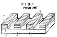
- Fig. 1 shows the structure of a piezoelectric element.
- the piezoelectric element 10 is structured in a rectangular shape.
- the piezoelectric element 10 has piezoelectric lamination portions 13 and electrodes 11 that are alternately formed.
- a vertical mechanical distortion takes place.
- ink droplets are sprayed from the nozzle of the ink reservoir.
- a plurality of nozzles corresponding to a plurality of ink reservoirs for cyan ink, magenta ink, yellow ink, and black ink are used.
- Fig. 2 is a schematic diagram showing the structure of a printer apparatus including a printer head peripheral portion using piezoelectric elements 10.
- the printer apparatus comprises ink reservoirs 23, a carrier 22, a SP (spacing) motor 26, a shaft 24, an LF(line field) motor 25, a platen 28, and a flat flexible cable (FFC) 27.
- the carrier 22 travels heads (not shown) in the main scanning direction.
- the SP motor 26 drives the carrier 22.
- the shaft 24 is used to travel the carrier 22.
- the LF motor 25 feeds paper 21 in the sub-scanning direction.
- the FFC 27 bends as the carrier 22 travels.
- the paper 21 is fed in the sub-scanning direction by the LF motor 25, the platen 28, a feed roller (not shown), and so forth.
- the carrier 22 is traveled along the shaft 24 by the SP motor 26.
- a drive signal and a control signal are supplied to the heads through the FFC 27 so that ink droplets are sprayed to the paper 21 at a predetermined timing.
- the ink reservoirs 23 and the heads are connected with respective tubes(not shown). Inks in the ink reservoirs 23 are supplied to the heads. When the piezoelectric elements 10 are driven, they are deformed. Thus, the heads are partly stressed and thereby inks in the heads are partly sprayed from the respective nozzles. Consequently, an image is formed on the paper 21.
- the capacitance component C of the time constant RC of which the resistance component R and the capacitance component C are multiplied becomes large.
- the piezoelectric elements are used for an ink jet printer, the velocity and size of ink droplets sprayed from the heads cannot be accurately controlled. Thus, the print quality of a print image is deteriorated.
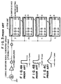
- the piezoelectric element driving circuit shown in Fig. 3 comprises a drive waveform signal generating circuit 1, a power amplifier 2, a flexible flat cable (FFC) 3, a plurality of head units 4, a plurality of switch devices 5, and a plurality of piezoelectric elements 6.
- the drive waveform signal generating circuit 1 generates a drive waveform signal for driving a plurality of piezoelectric elements 6.
- the power amplifier 2 amplifies the drive waveform signal.
- the FFC 3 connects the power amplifier 2 and the head units 4.
- the switch devices 5 are disposed in the head units 4.
- the piezoelectric elements 6 are connected to the switch device 5 of each of the head units 4.
- the head units 4 are color head units for cyan c, magenta m, yellow y, and black b.
- Each of the head units 4 has, for example, 32 nozzles.
- Each piezoelectric element 6 can be represented as a capacitance on an equivalent circuit diagram. Thus, corresponding to 32 nozzles of each color head unit, there is a capacitance of 32 capacitors.
- Fig. 4A shows an output waveform signal of a piezoelectric element driving power amplifier.
- the output waveform signal of the piezoelectric element driving power amplifier becomes an input waveform signal of an RC filter composed of a resistance component R of an FFC and the capacitance component C of piezoelectric elements.
- Hiroyuki Masunaga has disclosed a piezoelectric element driving circuit as Japanese Patent Laid-Open Publication No. 4-290585.
- a resistor module having a plurality of resistors connected in parallel is disposed.
- An on/off control signal for driving piezoelectric vibrators is input to the resistor module.
- An analog switch circuit selects one of resistors from the resistor module corresponding to a selection signal.
- a signal that passes through the selected resistor is compared with a reference voltage by an operational amplifier circuit.
- a voltage proportional to the difference is applied to the piezoelectric vibrators.
- the deviation of the characteristics of the individual piezoelectric vibrators is adjusted.
- An object of the present invention is to provide a driving circuit for directly driving an applied pulse waveform signal without an increase of the time constant of a plurality of piezoelectric elements that are driven.
- a first aspect of the present invention is a piezoelectric element driving circuit for driving a plurality of piezoelectric elements disposed in a plurality of head units, comprising a plurality of power amplifiers for driving the plurality of head units, a plurality of flexible flat cables for connecting the plurality of head units and the plurality of power amplifiers, and a drive waveform signal generating circuit for supplying a drive waveform signal to the plurality of head units through said plurality of power amplifiers, wherein each of the plurality of head units has a switch device for supplying a piezoelectric element current to the plurality of piezoelectric elements, wherein the plurality of power amplifiers are disposed corresponding to the plurality of head units, the plurality of power amplifiers supplying a drive waveform signal that is input from the drive waveform signal generating circuit to the plurality of power amplifiers so as to drive the plurality of head units.
- a second aspect of the present invention is a piezoelectric element driving method for driving a plurality of piezoelectric elements disposed in a plurality of head units, each of which has a plurality of power amplifiers for driving the plurality of head units, a plurality of flexible flat cables for connecting the plurality of head units and the plurality of power amplifiers, and a drive waveform signal generating circuit for supplying a drive waveform signal to the plurality of head units, the method comprising the steps of driving the plurality of power amplifiers so as to amplify the drive waveform signal, and causing the plurality of head units to spray large ink droplets, middle ink droplets, or small ink droplets corresponding to the drive waveform signal that is output from the drive waveform signal generating circuit, wherein when the small ink droplets are sprayed, the time constant of the plurality of power amplifiers that are driven allows the number of piezoelectric elements that are simultaneously driven becomes the maximum.
- a third aspect of the present invention is a piezoelectric element driving system, used in a printer apparatus, for driving a plurality of piezoelectric elements disposed in a plurality of head units, comprising a plurality of power amplifiers driven for the respective head units, a plurality of flexible flat cables for connecting the plurality of head units and the plurality of power amplifiers, a drive waveform signal generating circuit for supplying a drive waveform signal to the plurality of power amplifiers, print paper to which ink is sprayed from the plurality of head units driven by the plurality of power amplifiers so as to print characters and so forth on the print paper, a mechanical portion for driving the print paper in a sub-scanning direction and traveling the head units in a main scanning direction, wherein the head units spray large ink droplets, middle ink droplets, and small ink droplets driven by the plurality of power amplifiers that amplify the drive waveform signal.
- a fourth aspect of the present invention is a piezoelectric element driving circuit for driving a plurality of piezoelectric elements disposed in a plurality of head units, comprising a plurality of power amplifiers for driving the plurality of piezoelectric elements disposed in the plurality of head units, a plurality of first switch devices, disposed corresponding to the plurality of power amplifiers, having a plurality of connection/disconnection switches whose input side is short-circuited, a plurality of flexible cables connected to the connection/disconnection switches of the plurality of first switch devices, and a plurality of second switch devices, disposed corresponding to the plurality of head units, having a plurality of connection/disconnection switches whose input side is connected to the plurality of flexible cables and whose output side is short-circuited and connected to the plurality of head units, wherein the output side of the connection/disconnection switches of the plurality of first switch devices and the input side of the connection/disconnection switches of the plurality of second switch devices are paired and
- the waveform signal generated by the waveform signal generating circuit is amplified by the plurality of power amplifiers.
- the amplifiers are connected to respective head units.
- the load driven by each power amplifier is suppressed.
- the distortion of the drive waveform signal against the variation of the load is suppressed.
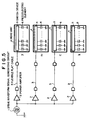
- reference numeral 1 is a drive waveform signal generating circuit that generates a drive waveform signal for driving a plurality of piezoelectric elements.
- Reference numeral 2 is a power amplifier that amplifies the drive waveform signal. There are a plurality of power amplifiers 2.
- Reference numeral 3 is a flexible flat cable (FFC). There are a plurality of FFC 3.
- Reference numeral 4 is a head unit. There are a plurality of head units 4. The FFCs 3 connects the power amplifiers 2 and the respective head units 4 through respective connectors.
- Reference numeral 5 is a switch device disposed in each of the head units 4.
- Reference numeral 6 is a piezoelectric element. There are a plurality of piezoelectric elements 6. The piezoelectric elements 6 are connected to the switch device 5 of each of the head units 4.
- Fig. 6 shows the detailed structure of each head unit 4.
- a drive waveform signal is sent to piezoelectric elements 6 through individual switches 7 of a switch device 5.
- the switch device 5 has a switch controlling circuit that controls the connection/disconnection of the switches 7.
- the switches 7 are for example semiconductor switches.
- the head unit 4 receives data, a clock signal, a latch signal, and so forth through an FFC 3.
- a serial/parallel converter 9 converts a serial signal into a parallel signal corresponding to the clock signal.
- a latch circuit 8 temporarily latches the parallel signal.
- the switches 7 are turned on/off corresponding to the parallel signal.
- the piezoelectric elements 6 are driven through the switches 7.
- the power amplifier 2 outputs drive waveform signals for large droplets, middle droplets, and small droplets.
- each head unit has 32 piezoelectric elements 6.
- the maximum number of piezoelectric elements 6 that the power amplifier 2 can drive is 32.
- the number of piezoelectric elements 6 of one head unit 4 connected to one power amplifier 2 is restricted so that the total amount of the static capacitance of the piezoelectric elements 6 does not become large.
- one power amplifier 2 is connected to one head unit 4.
- 32 piezoelectric elements are connected to one head unit 4.
- the 32 piezoelectric elements are connected to one power amplifier 2 through the switch device 5 and the FFC 3.
- Each head unit 4 is connected to one power amplifier 2.
- the static capacitance of the piezoelectric element 6 is connected to the power amplifier 2 through the line resistance of the FFC 3.
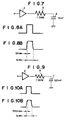
- Fig. 7 shows an equivalent circuit of which the static capacitance of one piezoelectric element 6 is 10 nF and the line resistance of the FFC 3 is 1 ohm.
- a waveform signal shown in Fig. 10A When a drive waveform signal shown in Fig. 10A is output from the power amplifier 2, a waveform signal shown in Fig. 10B is input to the piezoelectric element 6. Regardless of whether the number of piezoelectric elements 6 as a load is 1 or 32, the drive waveform signal that is input to the piezoelectric elements 6 does not largely vary. Thus, the print quality of an image printed on paper does not deteriorate.
- Figs. 11A to 11C show drive waveform signals.
- the horizontal axis and the vertical axis represent time and input voltage of the head unit, respectively.
- Fig. 11A shows the rounding of a drive waveform signal for spraying large droplets in the case that the number of nozzles that are simultaneously driven is 1, 32, and 64. .
- the right side of Fig. 11A is a partially enlarged view of the graph.
- Fig. 11B shows the rounding of a drive waveform signal for spraying middle droplets in the cases that the number of nozzles that are simultaneously driven is 1, 32, 64, and 160.
- Fig. 11C shows the rounding of a drive waveform signal for spraying small droplets in the cases that the number of nozzles that are simultaneously driven is 1, 32, 64, and 160.
- Figs. 11A, 11B, and 11C show that since the drive waveform signal for spraying small droplets most sharply vary in a short time, the rounding of the drive waveform signal due to the time constant is the largest.
- the time constant should be selected in such a manner that when small droplets are sprayed the maximum number of piezoelectric elements 6 of the head unit 4 are driven.
- the time constant is selected for small droplets. As long as the time constant is smaller than 400 nsec, the image quality of an image printed on print paper does not deteriorate.
- the velocity of large droplets against the number of nozzles to be driven in the case that the number of nozzles is around 300 is around 80 % of that in the case that the number of nozzles is one.
- the velocity of middle droplets against the number of nozzles to be driven in the case that the number of nozzles is around 300 is 50 % or less of that in the case that the number of nozzles is one.
- the velocity of small droplets against the number of nozzles to be driven in the case that the number of nozzles is around 300 is 30 % or less of that in the case that the number of nozzles is one.
- 100 or more nozzles cannot be driven.
- the velocity of droplets largely depends on the rounding of the drive waveform signal as well as the characteristics of the head, the drive waveform signal, the material of ink, and viscosity of ink, and so forth.
- the time constant of the drive system and the drive amplitude waveforms are very important.
- a drive waveform signal that is output from a power amplifier 2 is sent to piezoelectric elements 6 through FFCs 3.
- a plurality of power amplifiers 2 is used so as to decrease the capacitance C of the piezoelectric elements.
- the same effect is obtained by decreasing the resistance R.
- FIG. 13 is a block diagram showing the structure of a piezoelectric element driving circuit according to the third embodiment of the present invention.
- a head unit 4 slides.
- the head unit 4 is an integrated head unit having a yellow head unit 41, a magenta head unit 42, a cyan head unit 43, and a black head unit 44.
- the yellow head unit 41 has 32 piezoelectric elements and sprays yellow ink.
- the magenta head unit 42 has 32 piezoelectric elements and sprays magenta ink.
- the cyan head unit 43 has 32 piezoelectric elements and sprays cyan ink.
- the black head unit 44 has 32 piezoelectric elements and sprays black ink.
- a power amplifier 1, a switch device SW1, a copper foil FC1, and a switch device SW5 are connected in series.
- the power amplifier 1 drives piezoelectric elements of the yellow head unit 41.
- the switch device SW1 selects a switch corresponding to the number of piezoelectric elements to be driven.
- the copper foil FC1 is one cable part of the flexible cable 3 connected to the yellow head unit 41.
- the switch device SW5 selects a switch corresponding to the number of piezoelectric elements.
- piezoelectric elements of the magenta head unit 42 are driven by a power amplifier 2, a switch device SW2, a copper foil FC 2, and a switch device SW6.
- Piezoelectric elements of the cyan head unit 43 are driven by a power amplifier 3, a switch device SW3, a copper foil FC3, and a switch device 7.
- Piezoelectric elements of the black head unit 44 are driven by a power amplifier 4, a switch device SW4, a copper foil 4, and a switch device SW8.
- the switch devices SW1 to SW8 each have four switches. Switches SW11, SW21, SW31, and SW41 of the switch devices SW1 to SW4 are short-circuited on the output side thereof. Likewise, switches SW12, SW22, SW32, and SW42 of the switch devices SW1 to SW4 are short-circuited on the output side thereof. Likewise, switches SW13, SW23, SW33, and SW34 of the switch devices SW1 to SW4 are short-circuited on the output side thereof. Likewise, switches SW14, SW24, SW34, and SW44 of the switch devices SW1 to SW4 are short-circuited on the output side thereof.
- Switches SW51, SW61, SW71, and SW81 of the switch devices SW5 to SW8 are short-circuited on the input side thereof.
- switches SW52, SW62, SW72, and SW82 of the switch devices SW5 to SW8 are short-circuited on the input side thereof.
- switches SW53, SW63, SW73, and SW83 of the switch devices SW5 to SW8 are short-circuited on the input side thereof.
- switches SW54, SW64, SW74, and SW84 of the switch devices SW5 to SW8 are short-circuited on the input side thereof.
- the switches of each of the switch devices SW1 to SW4 are short-circuited on the input side thereof.
- a connection controlling circuit (not shown) controls the connection/disconnection of each switch of the switch devices SW1 to SW8.
- the connection/disconnection of each of the switches SW11 to SW14 of the switch device SW1 is controlled.
- the output signal of the power amplifier 2 is input to the magenta head unit 42 through the switch device SW2, the flexible cable FC2 and FC4, and the switch device SW6.
- the time constant of the resistance component 2R of the flexible cable FC1 and FC3 and the flexible cable FC2 and FC4 that are connected in parallel and the capacitance component C/2 of the piezoelectric elements that are simultaneously driven is 1/2 as small as that of the flexible cable FC1 and FC2.
- the loss of the frequency component of the drive waveform signal due to RC on the transmission path decreases. Consequently, even if a plurality of piezoelectric elements is driven, output signals of the power amplifiers are input to the piezoelectric elements without deterioration. Thus, the piezoelectric elements can be effectively driven.
Landscapes
- Particle Formation And Scattering Control In Inkjet Printers (AREA)
- Apparatuses For Generation Of Mechanical Vibrations (AREA)
- Ink Jet (AREA)
Abstract
Description
Claims (7)
- A piezoelectric element driving circuit for driving a plurality of piezoelectric elements disposed in a plurality of head units, comprising:a plurality of power amplifiers for driving the plurality of head units;a plurality of flexible flat cables disposed between said plurality of power amplifiers and the plurality of head units for connecting the plurality of head units and said plurality of power amplifiers; anda drive waveform signal generating circuit for supplying a drive waveform signal to said plurality of power amplifiers and the plurality of head units,
wherein each of the plurality of head units has:a switch device for supplying a piezoelectric element current to the plurality of piezoelectric elements,
wherein said plurality of power amplifiers are disposed corresponding to the plurality of head units, said plurality of power amplifiers supplying a drive waveform signal that is input from said drive waveform signal generating circuit to said plurality of power amplifiers through said plurality of flexible flat cables so as to drive the plurality of head units. - The piezoelectric element driving circuit as set forth in claim 1,
wherein said plurality of power amplifiers amplify the drive waveform signal that is output from said drive waveform signal generating circuit to the piezoelectric elements, said plurality of power amplifiers are connected to the respective head units, and the time constant of said plurality of power amplifiers are suppressed so as to control the velocities of inks sprayed from the plurality of head units. - A piezoelectric element driving circuit for driving a plurality of piezoelectric elements disposed in a plurality of head units, comprising:a plurality of power amplifiers for driving the plurality of piezoelectric elements disposed in the plurality of head units;a plurality of first switch devices, disposed corresponding to said plurality of power amplifiers, having a plurality of connection/disconnection switches whose input side is short-circuited;a plurality of flexible cables connected to the connection/disconnection switches of said plurality of first switch devices; anda plurality of second switch devices, disposed corresponding to said plurality of head units, having a plurality of connection/disconnection switches whose input side is connected to said plurality of flexible cables and whose output side is short-circuited and connected to the plurality of head units,
wherein the output side of the connection/disconnection switches of said plurality of first switch devices and the input side of the connection/disconnection switches of said plurality of second switch devices are paired and connected,
wherein the connection/disconnection of the connection/disconnection switches of said plurality of first switch devices and said plurality of second switch devices is controlled corresponding to the number of piezoelectric elements to be driven so as to decrease the time constant of said plurality of power amplifiers to a predetermined value or less. - The piezoelectric element driving circuit as set forth in claim 1, 2, or 3,
wherein the plurality of piezoelectric elements of the plurality of head units are vibrated so as to spray large ink droplets, middle ink droplets, or small ink droplets, and
wherein when the small ink droplets are sprayed, the drive waveform signal is generated for a time constant that allows the number of piezoelectric elements that are simultaneously driven becomes the maximum. - The piezoelectric element driving circuit as set forth in claim 1 , 2, 3, or 4
wherein the head units are a yellow head unit, a magenta head unit, a cyan head unit, and a black head unit that spray yellow ink, magenta ink, cyan ink, and black ink, respectively,
wherein the head units spray large ink droplets, middle ink droplets, or small ink droplets of the individual colors corresponding to the number of piezoelectric elements of each of the head units connected to said plurality of power amplifiers and the level of the drive waveform signal, and
wherein when the small ink droplets are sprayed, the drive waveform signal is generated for a time constant that allows the number of piezoelectric elements that are simultaneously driven becomes the maximum. - A piezoelectric element driving method for driving a plurality of piezoelectric elements disposed in a plurality of head units, each of which has a plurality of power amplifiers for driving the plurality of head units, a plurality of flexible flat cables for connecting the plurality of head units and said plurality of power amplifiers, and a drive waveform signal generating circuit for supplying a drive waveform signal to the plurality of head units,the method comprising the steps of:driving the plurality of power amplifiers so as to amplify the drive waveform signal; andcausing the plurality of head units to spray large ink droplets, middle ink droplets, or small ink droplets corresponding to the drive waveform signal that is output from the drive waveform signal generating circuit,
wherein when the small ink droplets are sprayed, the time constant of the plurality of power amplifiers that are driven allows the number of piezoelectric elements that are simultaneously driven becomes the maximum. - The method as set forth in claim 6,
wherein the time constant of the plurality of power amplifiers that are driven is equal to or smaller than a predetermined value of which all the plurality of piezoelectric elements are driven in the case that all outputs of a latch circuit that latches an output of a data serial parallel converter of each of the plurality of head units are turned on and all switches connected to all the piezoelectric elements are turned on.
Applications Claiming Priority (2)
| Application Number | Priority Date | Filing Date | Title |
|---|---|---|---|
| JP14364799 | 1999-05-24 | ||
| JP11143647A JP2000325882A (en) | 1999-05-24 | 1999-05-24 | Piezoelectric drive circuit and drive method |
Publications (2)
| Publication Number | Publication Date |
|---|---|
| EP1057635A2 true EP1057635A2 (en) | 2000-12-06 |
| EP1057635A3 EP1057635A3 (en) | 2002-04-10 |
Family
ID=15343657
Family Applications (1)
| Application Number | Title | Priority Date | Filing Date |
|---|---|---|---|
| EP00110280A Withdrawn EP1057635A3 (en) | 1999-05-24 | 2000-05-22 | Piezoelectric element driving circuit and driving method |
Country Status (4)
| Country | Link |
|---|---|
| US (1) | US6831392B2 (en) |
| EP (1) | EP1057635A3 (en) |
| JP (1) | JP2000325882A (en) |
| CN (1) | CN1274644A (en) |
Families Citing this family (9)
| Publication number | Priority date | Publication date | Assignee | Title |
|---|---|---|---|---|
| JP4222592B2 (en) | 2002-02-25 | 2009-02-12 | 株式会社リコー | Multilayer piezoelectric element and method for manufacturing the same, piezoelectric actuator, droplet discharge head, and ink jet recording apparatus |
| JP4771042B2 (en) * | 2004-07-23 | 2011-09-14 | ゲットナー・ファンデーション・エルエルシー | Piezoelectric element mounting apparatus, droplet discharge apparatus using the same, and image output apparatus |
| JP2006088577A (en) * | 2004-09-24 | 2006-04-06 | Fuji Xerox Co Ltd | Inspection device of inkjet head |
| JP4877234B2 (en) * | 2006-01-20 | 2012-02-15 | セイコーエプソン株式会社 | Inkjet printer head drive device and inkjet printer |
| JP5014048B2 (en) * | 2006-10-04 | 2012-08-29 | キヤノン株式会社 | Element substrate and recording head, head cartridge, and recording apparatus using the element substrate |
| JP5128404B2 (en) * | 2008-07-25 | 2013-01-23 | シャープ株式会社 | Voltage amplification circuit and drive circuit |
| EP2528739A4 (en) | 2010-01-29 | 2013-10-02 | Hewlett Packard Development Co | REDUCING CROSSTALK IN A PIEZOELECTRIC PRINTING HEAD |
| CN102653168B (en) * | 2011-03-02 | 2014-12-03 | 北京美科艺数码科技发展有限公司 | Nozzle driving circuit for inkjet printers |
| CN109927291B (en) * | 2017-12-15 | 2020-11-03 | 中国科学院沈阳自动化研究所 | A driving device and method for 3D printing head suitable for high-viscosity biological materials |
Family Cites Families (13)
| Publication number | Priority date | Publication date | Assignee | Title |
|---|---|---|---|---|
| US5834871A (en) * | 1996-08-05 | 1998-11-10 | Puskas; William L. | Apparatus and methods for cleaning and/or processing delicate parts |
| JPS6371705A (en) | 1986-09-16 | 1988-04-01 | Hitachi Ltd | Piezo element drive circuit |
| JPH01118447A (en) * | 1987-10-30 | 1989-05-10 | Brother Ind Ltd | impact printer |
| JPH02137967A (en) * | 1988-11-18 | 1990-05-28 | Seikosha Co Ltd | Serial printer |
| JP2536114B2 (en) * | 1989-01-18 | 1996-09-18 | トヨタ自動車株式会社 | Driving device for piezoelectric element |
| US5387834A (en) * | 1990-07-11 | 1995-02-07 | Brother Kogyo Kabushiki Kaisha | Piezoelectric element driving circuit |
| JPH04290585A (en) * | 1991-03-18 | 1992-10-15 | Nec Data Terminal Ltd | Piezo driving circuit |
| JPH04316851A (en) * | 1991-04-16 | 1992-11-09 | Sharp Corp | Drive circuit of ink jet multinozzle head |
| JPH05169686A (en) * | 1991-10-11 | 1993-07-09 | Brother Ind Ltd | Piezoelectric element drive circuit |
| JPH06959A (en) * | 1992-06-22 | 1994-01-11 | Seiko Epson Corp | Ink jet recorder |
| JPH08177678A (en) | 1994-12-28 | 1996-07-12 | Nippondenso Co Ltd | Piezo-actuator drive circuit |
| JP3346454B2 (en) * | 1997-01-08 | 2002-11-18 | セイコーエプソン株式会社 | Ink jet printing apparatus and printing method |
| US6039428A (en) * | 1998-05-13 | 2000-03-21 | Hewlett-Packard Company | Method for improving ink jet printer reliability in the presence of ink shorts |
-
1999
- 1999-05-24 JP JP11143647A patent/JP2000325882A/en active Pending
-
2000
- 2000-05-22 EP EP00110280A patent/EP1057635A3/en not_active Withdrawn
- 2000-05-23 US US09/576,492 patent/US6831392B2/en not_active Expired - Fee Related
- 2000-05-24 CN CN00107735.XA patent/CN1274644A/en active Pending
Also Published As
| Publication number | Publication date |
|---|---|
| US6831392B2 (en) | 2004-12-14 |
| US20020008441A1 (en) | 2002-01-24 |
| JP2000325882A (en) | 2000-11-28 |
| EP1057635A3 (en) | 2002-04-10 |
| CN1274644A (en) | 2000-11-29 |
Similar Documents
| Publication | Publication Date | Title |
|---|---|---|
| JP6950218B2 (en) | Liquid discharge device and circuit board | |
| CN109130506B (en) | Liquid ejection device and flexible flat cable | |
| US8201905B2 (en) | Head drive apparatus of ink jet printer, head driving method, and ink jet printer | |
| JPWO2001053102A1 (en) | Recording head driving method, recording head, and inkjet printer | |
| JP2012196820A (en) | Liquid ejecting apparatus and liquid ejecting method | |
| JP6604191B2 (en) | Liquid discharge device and flexible flat cable group | |
| EP1057635A2 (en) | Piezoelectric element driving circuit and driving method | |
| CN112140725B (en) | Liquid ejecting apparatus, drive circuit, and integrated circuit | |
| CN107053844A (en) | Printing equipment and transmission cable | |
| JP4218245B2 (en) | Inkjet printer | |
| US20060044337A1 (en) | Image forming apparatus and drive control method for liquid ejection head | |
| US8608267B2 (en) | Ink jetting | |
| JP6369057B2 (en) | Semiconductor device, liquid discharge head, and liquid discharge device | |
| US6290317B1 (en) | Inkjet printing apparatus | |
| JP2019199053A (en) | Liquid discharge device | |
| JP4576917B2 (en) | Inkjet recording device | |
| JP6717367B2 (en) | Liquid ejector | |
| CN104339862B (en) | Liquid ejecting apparatus | |
| JP2009196197A (en) | Liquid jet device | |
| US6293640B1 (en) | Printing apparatus and printing method | |
| JP2004195792A (en) | Ink jet recording device | |
| CN116529088B (en) | Recording head and recording apparatus | |
| JP2001277553A (en) | Line printer | |
| EP4328035B1 (en) | Ink jet head | |
| JP2004058662A (en) | Ink jet head and ink jet recording apparatus |
Legal Events
| Date | Code | Title | Description |
|---|---|---|---|
| PUAI | Public reference made under article 153(3) epc to a published international application that has entered the european phase |
Free format text: ORIGINAL CODE: 0009012 |
|
| AK | Designated contracting states |
Kind code of ref document: A2 Designated state(s): AT BE CH CY DE DK ES FI FR GB GR IE IT LI LU MC NL PT SE Kind code of ref document: A2 Designated state(s): DE FR GB IT |
|
| AX | Request for extension of the european patent |
Free format text: AL;LT;LV;MK;RO;SI |
|
| PUAL | Search report despatched |
Free format text: ORIGINAL CODE: 0009013 |
|
| AK | Designated contracting states |
Kind code of ref document: A3 Designated state(s): AT BE CH CY DE DK ES FI FR GB GR IE IT LI LU MC NL PT SE |
|
| AX | Request for extension of the european patent |
Free format text: AL;LT;LV;MK;RO;SI |
|
| 17P | Request for examination filed |
Effective date: 20020227 |
|
| RAP1 | Party data changed (applicant data changed or rights of an application transferred) |
Owner name: FUJI XEROX CO., LTD. |
|
| 17Q | First examination report despatched |
Effective date: 20020719 |
|
| AKX | Designation fees paid |
Free format text: DE FR GB IT |
|
| STAA | Information on the status of an ep patent application or granted ep patent |
Free format text: STATUS: THE APPLICATION IS DEEMED TO BE WITHDRAWN |
|
| 18D | Application deemed to be withdrawn |
Effective date: 20021130 |