EP1057617A2 - Process for fabricating plastic optical fiber - Google Patents
Process for fabricating plastic optical fiber Download PDFInfo
- Publication number
- EP1057617A2 EP1057617A2 EP00304068A EP00304068A EP1057617A2 EP 1057617 A2 EP1057617 A2 EP 1057617A2 EP 00304068 A EP00304068 A EP 00304068A EP 00304068 A EP00304068 A EP 00304068A EP 1057617 A2 EP1057617 A2 EP 1057617A2
- Authority
- EP
- European Patent Office
- Prior art keywords
- diffusion
- dopant
- polymer
- core
- fiber
- Prior art date
- Legal status (The legal status is an assumption and is not a legal conclusion. Google has not performed a legal analysis and makes no representation as to the accuracy of the status listed.)
- Withdrawn
Links
- 238000000034 method Methods 0.000 title claims abstract description 85
- 230000008569 process Effects 0.000 title claims abstract description 68
- 239000013308 plastic optical fiber Substances 0.000 title claims abstract description 14
- 239000000835 fiber Substances 0.000 claims abstract description 74
- 238000004458 analytical method Methods 0.000 claims abstract description 17
- 238000009792 diffusion process Methods 0.000 claims description 210
- 239000002019 doping agent Substances 0.000 claims description 101
- 229920000642 polymer Polymers 0.000 claims description 66
- 239000000463 material Substances 0.000 claims description 52
- 239000002861 polymer material Substances 0.000 claims description 43
- 239000013307 optical fiber Substances 0.000 claims description 8
- 238000007380 fibre production Methods 0.000 claims description 7
- 230000009477 glass transition Effects 0.000 claims description 6
- 238000001125 extrusion Methods 0.000 abstract description 39
- 238000004519 manufacturing process Methods 0.000 abstract description 24
- 239000011162 core material Substances 0.000 description 114
- 238000005253 cladding Methods 0.000 description 75
- 230000000694 effects Effects 0.000 description 24
- 230000006870 function Effects 0.000 description 13
- 230000008707 rearrangement Effects 0.000 description 12
- 238000002474 experimental method Methods 0.000 description 8
- 238000012545 processing Methods 0.000 description 7
- 230000007704 transition Effects 0.000 description 7
- 230000001419 dependent effect Effects 0.000 description 6
- 239000012530 fluid Substances 0.000 description 6
- 230000005540 biological transmission Effects 0.000 description 5
- 238000004364 calculation method Methods 0.000 description 5
- 230000003247 decreasing effect Effects 0.000 description 5
- 229920006240 drawn fiber Polymers 0.000 description 5
- 238000004088 simulation Methods 0.000 description 5
- 239000011521 glass Substances 0.000 description 4
- -1 poly(methyl methacrylate) Polymers 0.000 description 4
- DFPAKSUCGFBDDF-UHFFFAOYSA-N Nicotinamide Chemical compound NC(=O)C1=CC=CN=C1 DFPAKSUCGFBDDF-UHFFFAOYSA-N 0.000 description 3
- DNIAPMSPPWPWGF-UHFFFAOYSA-N Propylene glycol Chemical compound CC(O)CO DNIAPMSPPWPWGF-UHFFFAOYSA-N 0.000 description 3
- 238000010438 heat treatment Methods 0.000 description 3
- 229920003229 poly(methyl methacrylate) Polymers 0.000 description 3
- 239000004926 polymethyl methacrylate Substances 0.000 description 3
- IRIAEXORFWYRCZ-UHFFFAOYSA-N Butylbenzyl phthalate Chemical compound CCCCOC(=O)C1=CC=CC=C1C(=O)OCC1=CC=CC=C1 IRIAEXORFWYRCZ-UHFFFAOYSA-N 0.000 description 2
- 239000004809 Teflon Substances 0.000 description 2
- 229920006362 Teflon® Polymers 0.000 description 2
- SESFRYSPDFLNCH-UHFFFAOYSA-N benzyl benzoate Chemical compound C=1C=CC=CC=1C(=O)OCC1=CC=CC=C1 SESFRYSPDFLNCH-UHFFFAOYSA-N 0.000 description 2
- 230000015572 biosynthetic process Effects 0.000 description 2
- QARVLSVVCXYDNA-UHFFFAOYSA-N bromobenzene Chemical compound BrC1=CC=CC=C1 QARVLSVVCXYDNA-UHFFFAOYSA-N 0.000 description 2
- 238000004422 calculation algorithm Methods 0.000 description 2
- 238000005229 chemical vapour deposition Methods 0.000 description 2
- UUAGAQFQZIEFAH-UHFFFAOYSA-N chlorotrifluoroethylene Chemical group FC(F)=C(F)Cl UUAGAQFQZIEFAH-UHFFFAOYSA-N 0.000 description 2
- 229920001577 copolymer Polymers 0.000 description 2
- 238000005260 corrosion Methods 0.000 description 2
- 230000007797 corrosion Effects 0.000 description 2
- 230000007423 decrease Effects 0.000 description 2
- 239000006185 dispersion Substances 0.000 description 2
- 230000001747 exhibiting effect Effects 0.000 description 2
- 238000009472 formulation Methods 0.000 description 2
- 239000011159 matrix material Substances 0.000 description 2
- 238000005259 measurement Methods 0.000 description 2
- 239000000155 melt Substances 0.000 description 2
- MYWUZJCMWCOHBA-VIFPVBQESA-N methamphetamine Chemical compound CN[C@@H](C)CC1=CC=CC=C1 MYWUZJCMWCOHBA-VIFPVBQESA-N 0.000 description 2
- 239000000203 mixture Substances 0.000 description 2
- 239000003607 modifier Substances 0.000 description 2
- 230000037361 pathway Effects 0.000 description 2
- 239000007787 solid Substances 0.000 description 2
- 239000000126 substance Substances 0.000 description 2
- JWKJOADJHWZCLL-UHFFFAOYSA-N 1,2,3,4,5,5,6,6,6-nonafluoro-1-(1,2,3,4,5,5,6,6,6-nonafluorohexa-1,3-dienoxy)hexa-1,3-diene Chemical compound FC(OC(F)=C(F)C(F)=C(F)C(F)(F)C(F)(F)F)=C(F)C(F)=C(F)C(F)(F)C(F)(F)F JWKJOADJHWZCLL-UHFFFAOYSA-N 0.000 description 1
- YSYRISKCBOPJRG-UHFFFAOYSA-N 4,5-difluoro-2,2-bis(trifluoromethyl)-1,3-dioxole Chemical compound FC1=C(F)OC(C(F)(F)F)(C(F)(F)F)O1 YSYRISKCBOPJRG-UHFFFAOYSA-N 0.000 description 1
- RYGMFSIKBFXOCR-UHFFFAOYSA-N Copper Chemical compound [Cu] RYGMFSIKBFXOCR-UHFFFAOYSA-N 0.000 description 1
- 239000004793 Polystyrene Substances 0.000 description 1
- 230000004913 activation Effects 0.000 description 1
- 238000013459 approach Methods 0.000 description 1
- 150000001491 aromatic compounds Chemical class 0.000 description 1
- 230000004323 axial length Effects 0.000 description 1
- 230000009286 beneficial effect Effects 0.000 description 1
- 230000008901 benefit Effects 0.000 description 1
- 229960002903 benzyl benzoate Drugs 0.000 description 1
- 230000015556 catabolic process Effects 0.000 description 1
- 230000008859 change Effects 0.000 description 1
- 238000006731 degradation reaction Methods 0.000 description 1
- 238000000151 deposition Methods 0.000 description 1
- 230000008021 deposition Effects 0.000 description 1
- 238000013461 design Methods 0.000 description 1
- DWNAQMUDCDVSLT-UHFFFAOYSA-N diphenyl phthalate Chemical compound C=1C=CC=C(C(=O)OC=2C=CC=CC=2)C=1C(=O)OC1=CC=CC=C1 DWNAQMUDCDVSLT-UHFFFAOYSA-N 0.000 description 1
- LTYMSROWYAPPGB-UHFFFAOYSA-N diphenyl sulfide Chemical compound C=1C=CC=CC=1SC1=CC=CC=C1 LTYMSROWYAPPGB-UHFFFAOYSA-N 0.000 description 1
- 238000009826 distribution Methods 0.000 description 1
- 230000009977 dual effect Effects 0.000 description 1
- 238000011156 evaluation Methods 0.000 description 1
- 239000004811 fluoropolymer Substances 0.000 description 1
- 229920002313 fluoropolymer Polymers 0.000 description 1
- 230000004907 flux Effects 0.000 description 1
- 239000008187 granular material Substances 0.000 description 1
- 229910000856 hastalloy Inorganic materials 0.000 description 1
- 125000005842 heteroatom Chemical group 0.000 description 1
- 230000006872 improvement Effects 0.000 description 1
- 239000012535 impurity Substances 0.000 description 1
- 230000007774 longterm Effects 0.000 description 1
- 238000003754 machining Methods 0.000 description 1
- 230000004048 modification Effects 0.000 description 1
- 238000012986 modification Methods 0.000 description 1
- 230000003287 optical effect Effects 0.000 description 1
- 238000005191 phase separation Methods 0.000 description 1
- 239000004033 plastic Substances 0.000 description 1
- 229920003023 plastic Polymers 0.000 description 1
- 239000004417 polycarbonate Substances 0.000 description 1
- 229920000515 polycarbonate Polymers 0.000 description 1
- 229920002223 polystyrene Polymers 0.000 description 1
- 239000000843 powder Substances 0.000 description 1
- 230000001105 regulatory effect Effects 0.000 description 1
- 230000004044 response Effects 0.000 description 1
- 238000000518 rheometry Methods 0.000 description 1
- 238000013341 scale-up Methods 0.000 description 1
- 238000010206 sensitivity analysis Methods 0.000 description 1
- 150000003384 small molecules Chemical class 0.000 description 1
- 230000007480 spreading Effects 0.000 description 1
- 238000003892 spreading Methods 0.000 description 1
- BFKJFAAPBSQJPD-UHFFFAOYSA-N tetrafluoroethene Chemical group FC(F)=C(F)F BFKJFAAPBSQJPD-UHFFFAOYSA-N 0.000 description 1
- 229920006352 transparent thermoplastic Polymers 0.000 description 1
- XLYOFNOQVPJJNP-UHFFFAOYSA-N water Substances O XLYOFNOQVPJJNP-UHFFFAOYSA-N 0.000 description 1
Images



Classifications
-
- G—PHYSICS
- G02—OPTICS
- G02B—OPTICAL ELEMENTS, SYSTEMS OR APPARATUS
- G02B6/00—Light guides; Structural details of arrangements comprising light guides and other optical elements, e.g. couplings
-
- B—PERFORMING OPERATIONS; TRANSPORTING
- B29—WORKING OF PLASTICS; WORKING OF SUBSTANCES IN A PLASTIC STATE IN GENERAL
- B29D—PRODUCING PARTICULAR ARTICLES FROM PLASTICS OR FROM SUBSTANCES IN A PLASTIC STATE
- B29D11/00—Producing optical elements, e.g. lenses or prisms
- B29D11/00663—Production of light guides
- B29D11/00682—Production of light guides with a refractive index gradient
-
- B—PERFORMING OPERATIONS; TRANSPORTING
- B29—WORKING OF PLASTICS; WORKING OF SUBSTANCES IN A PLASTIC STATE IN GENERAL
- B29C—SHAPING OR JOINING OF PLASTICS; SHAPING OF MATERIAL IN A PLASTIC STATE, NOT OTHERWISE PROVIDED FOR; AFTER-TREATMENT OF THE SHAPED PRODUCTS, e.g. REPAIRING
- B29C48/00—Extrusion moulding, i.e. expressing the moulding material through a die or nozzle which imparts the desired form; Apparatus therefor
- B29C48/03—Extrusion moulding, i.e. expressing the moulding material through a die or nozzle which imparts the desired form; Apparatus therefor characterised by the shape of the extruded material at extrusion
- B29C48/05—Filamentary, e.g. strands
-
- B—PERFORMING OPERATIONS; TRANSPORTING
- B29—WORKING OF PLASTICS; WORKING OF SUBSTANCES IN A PLASTIC STATE IN GENERAL
- B29C—SHAPING OR JOINING OF PLASTICS; SHAPING OF MATERIAL IN A PLASTIC STATE, NOT OTHERWISE PROVIDED FOR; AFTER-TREATMENT OF THE SHAPED PRODUCTS, e.g. REPAIRING
- B29C48/00—Extrusion moulding, i.e. expressing the moulding material through a die or nozzle which imparts the desired form; Apparatus therefor
- B29C48/25—Component parts, details or accessories; Auxiliary operations
- B29C48/30—Extrusion nozzles or dies
- B29C48/304—Extrusion nozzles or dies specially adapted for bringing together components, e.g. melts within the die
-
- B—PERFORMING OPERATIONS; TRANSPORTING
- B29—WORKING OF PLASTICS; WORKING OF SUBSTANCES IN A PLASTIC STATE IN GENERAL
- B29C—SHAPING OR JOINING OF PLASTICS; SHAPING OF MATERIAL IN A PLASTIC STATE, NOT OTHERWISE PROVIDED FOR; AFTER-TREATMENT OF THE SHAPED PRODUCTS, e.g. REPAIRING
- B29C48/00—Extrusion moulding, i.e. expressing the moulding material through a die or nozzle which imparts the desired form; Apparatus therefor
-
- B—PERFORMING OPERATIONS; TRANSPORTING
- B29—WORKING OF PLASTICS; WORKING OF SUBSTANCES IN A PLASTIC STATE IN GENERAL
- B29L—INDEXING SCHEME ASSOCIATED WITH SUBCLASS B29C, RELATING TO PARTICULAR ARTICLES
- B29L2011/00—Optical elements, e.g. lenses, prisms
- B29L2011/0075—Light guides, optical cables
Definitions
- the invention relates to fabrication of graded-index plastic optical fiber.
- Glass optical fiber has become a significant transmission medium in recent years, particularly for long distance transmission applications. Such optical fiber has not found significant usage, however, in smaller scale applications, such as distribution of fiber to the desk in local area networks.
- glass optical fiber has not been as cost effective as, for example, copper wire, and also requires extremely precise fiber connections.
- plastic optical fiber which offers many of the benefits of glass optical fiber, but is expected to be more cost effective.
- POF also offers a larger core, which makes connection and splicing easier.
- step index POF (having a core of one refractive index, surrounded by a cladding of a different refractive index) was manufactured and used.
- GI-POF graded-index POF
- GI-POF graded-index POF
- GI-POF was developed, which possesses a varying refractive index from the core to the cladding layer.
- GI-POF exhibits a lower level of mode dispersion, thereby providing improved properties.
- GI-POF was more difficult, and thus more expensive, to manufacture than step-index POF. Improved methods for manufacturing GI-POF were therefore sought.
- One method of forming GI-POF is to start with a preform, similar to the preform from which glass optical fiber is generally drawn. See, e.g., U.S. Patents Nos. 5,639,512 and 5,614,253, which discuss a process for chemical vapor deposition (CVD) formation of a preform for GI-POF.
- CVD chemical vapor deposition
- a polymer and a refractive index modifier are deposited onto a rod, and the amount of refractive index modifier is varied during the deposition to provide the desired refractive index profile. While such preforms are useful for preparing GI-POF, easier processes are desired.
- extrusion is commonly used with plastics to form a variety of items. Extrusion was expected to be quicker and cheaper than forming and drawing a preform, but the need for a graded refractive index profile created complications.
- U.S. Patent No. 5,593,621 discusses an extrusion process for GI-POF. According to the '621 patent, GI-POF is manufactured by extruding one material circumferentially around another material, e.g., by use of a concentric nozzle. At least one of the materials contains a diffusible material having a distinct refractive index, such that the diffusion of the material provides the desired refractive index contrast. The method of the '621 patent appears to offer a functional process, but also appears to exhibit several drawbacks.
- the process is able to be performed without providing a delay time (stopping the flow of material) or a very slow extrusion speed, to allow the diffusible material sufficient time to diffuse.
- the examples disclose a small distance, 3 cm, between the outlet of concentric nozzle 5 (see Fig. 1) and the outlet of core nozzle 3.
- this small contact distance allows sufficient diffusion, without requiring either intermittent stoppage or an extremely slow extrusion speed.
- Embodiment 6 states that diffusion was effected for about 3 minutes within this contact region, and Embodiments 7, 8, and 9 all state that diffusion occurred for about 10 minutes in the contact region.
- the reference does not disclose an extrusion speed nor make clear whether the process had to be halted intermittently.
- the invention provides a continuous extrusion process capable of producing graded index plastic optical fiber (GI-POF) at commercially acceptable speeds, e.g., at least 1 m/sec for 250 ⁇ m outer diameter fiber. Moreover, it is possible to predict the refractive index profile of the fiber, prior to actual fabrication, by performing a numerical analysis for various parameters of the extrusion process. Such prediction allows one to tune the parameters of the process to obtain a desirable outcome, while avoiding the need for substantial trial and error with the extrusion equipment.
- GGI-POF graded index plastic optical fiber
- the process involves introducing a first, e.g., core, polymer material into a first nozzle and introducing a second, e.g., cladding, polymer material into a second nozzle, where at least one of the polymer materials includes a diffusible dopant having a refractive index that changes the refractive index of the polymer material.
- the nozzles are arranged concentrically, the first nozzle located within the second nozzle such that the materials flow in a concentric manner upon introduction into a diffusion section 22.
- dopant diffusion takes place between and within the first and second polymer materials, such that the graded refractive index is achieved.
- the first and second polymer materials move continuously through the diffusion section 22, flow through an exit die 26, and are then drawn into fiber. (Continuous or continuously indicates that upon introduction into the diffusion section the polymer materials do not undergo intermittent stoppages at any point prior to flowing through the exit die.)
- the flow rate of polymer from the exit die is typically as high as 3 cm 3 /min, which corresponds to a production rate of at least 1 meter/sec for 250 ⁇ m diameter fiber, although it is possible to scale up the process to even higher flows, as discussed herein. It is therefore possible to avoid the intermittent stoppages and/or extremely slow flow rate apparently required by the process of the '621 patent, which in turn makes it possible to continuously extrude the GI-POF at commercially useful rates.
- parameters of the extrusion process are selected and material properties are determined prior to actual fabrication, based on a predicted dopant or refractive index profile.
- Relevant process and material characteristics include diffusion zone length and radius, flow rates of the core and cladding polymer materials, and dopant diffusivity in the core and cladding polymer materials.
- Other characteristics sometimes used include shear rate-dependent viscosities and densities of the first and second polymer materials (as functions of temperature), temperature of the diffusion section, and dopant mass fraction in the polymers.
- a numerical analysis is used to determine the expected dopant profile based on the provided values. The analysis makes it possible to determine the effect of varying any or all of these parameters, thereby avoiding much of the time-consuming and costly trial-and-error that would otherwise be required.
- core and cladding polymers are fed into, respectively, a core extruder 12 and a cladding extruder 14 of a fiber extrusion apparatus 10.
- the core and/or cladding polymer (typically the core polymer) contains one or more diffusible dopants that provide the desired graded index.
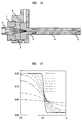
- the core polymer is fed from the core extruder 12 through a connector hose 16 into the co-extrusion head 20 (shown in more detail in Fig. 1B), and the cladding polymer is fed into the co-extrusion head 20 through a connector pipe 18. As shown in Fig.
- the co-extrusion head 20 contains a core nozzle 30 for directing the core polymer into the center of a diffusion section 22, while the cladding polymer from the connector pipe 18 is distributed concentrically around the core polymer into the diffusion section 22.
- the core polymer and cladding polymer flow together into the diffusion zone 24.
- the diffusion zone is the length of the section 22 that begins at the first point of contact of the core and cladding polymers (at the exit of nozzle 30) in the co-extrusion head 20 and ends at the lower end of the exit die 26.)
- the diffusion section 22 is generally heated to maintain flow of the molten polymer and promote diffusion of the diffusible dopant, and the zone 24 is of sufficient length to allow a desired extent of diffusion to occur.
- the polymers then flow from the section 22 into an exit die 26, which provides a desired diameter, and the exiting fiber is then pulled by a capstan 28 to draw the fiber at the necessary rate to obtain the desired final diameter of the fiber.
- the fiber is then typically taken up by a spool 34.
- a diameter monitor 32 is typically used to monitor the final diameter of the drawn fiber, such that adjustments can be made, if required.
- the polymers are typically added to the extruders in solid granular form, and melted therein. Alternatively, it is possible for the polymers to be fed into the extruders in powder or molten form, using conventional equipment.
- the invention is capable of producing graded-index plastic optical fibers from a variety of transparent thermoplastic polymers exhibiting useful refractive index, glass transition temperatures and optical transmission characteristics, and for which compatible, refractive index-altering dopants exhibiting sufficient mobility at processing temperatures in the polymer are available. Glass transition temperature typically ranges from about 90°C to about 260°C, refractive index typically ranges from about 1.3 to about 1.6, and transmission losses typically range from 10 to 1000 dB/km for the bulk polymer.
- Viscosities typically range from 100 to 1,000,000, and more typically 1000 to 100,000 poise.
- suitable polymers include poly(methyl methacrylate) (PMMA), polycarbonate, polystyrene, styrene-acrylonitride copolymers (SAN), poly(perfluoro-butenyl vinyl ether), (CYTOPTM) and copolymers of tetrafluoroethylene and 2,2 bistrifluoromethyl-4,5-difluoro-1,3-dioxole (Teflon AFTM).
- the dopant is typically an index-raising substance added to the core polymer.
- dopant indicates one or more diffusible materials.
- the dopant is an index-lowering substance added to the cladding polymer.
- Useful dopants are relatively low molecular weight compounds which: 1) are soluble in the polymers used for the GI-POF and do not phase-separate or crystallize in the polymers over time; 2) do not significantly increase the transmission loss of the polymers; 3) do not depress the glass transition temperature of the polymers by an unacceptable degree; 4) have sufficiently high diffusivities in the polymers at processing temperatures, e.g., 10 -8 to 10 -5 cm 2 /sec; 5) provide large changes in refractive indices at low concentrations in the polymers, e.g., ⁇ n > 0.015 for less than 15 wt.% dopant; 6) are chemically stable in the polymers at processing temperatures and in operating environments over the long term; 7) have low volatility at processing
- Suitable dopants include bromobenzene, benzylbutylphthalate, benzyl benzoate, diphenyl phthalate, and diphenyl sulfide for use with PMMA, and per-halogenated oligomers and per-halogenated aromatic compounds, which optionally include heteroatoms, for use with CYTOPTM or Teflon AFTM.
- the dopant undergoes molecular diffusion from the molten core (or cladding) polymer into the molten cladding (or core) polymer to form the refractive index profile. After exiting the die, the fiber rapidly cools to room temperature and the dopant becomes substantially immobilized in the polymer.
- the co-extrusion head as illustrated in Fig. 1B. is designed to distribute an annular or concentric cladding melt stream around a centrally-located core melt stream in a smooth, laminar flow without disruption of the core/cladding interface.
- the diffusion section is generally of substantially uniform cross-section to maintain a smooth flow, and is generally tubular.
- the typical average diameter of the section in the diffusion zone is about 0.25 cm to about 1.0 cm, advantageously about 0.50 cm (diameter referring to inner diameter).
- the diffusion zone temperature is regulated, advantageously in a uniform manner throughout the zone, to promote a desired level of polymer flow and dopant diffusion.
- diffusion zone temperature is the average temperature to which the section and the polymer therein is heated.
- the section is heated by any suitable technique, e.g., by using a series of band heaters or high temperature heating tapes.
- Typical diffusion zone temperatures range from about 150°C to about 300°C. It is possible for the zone to be made up of tubular elements capable of being threaded together, such that modification of the diffusion zone length is eased.
- Typical diffusion zone lengths are about 33 to about 400 cm, advantageously at least 50 cm, more advantageously at least 100 cm. This range of diffusion zone length, in combination with the above-noted temperature range, allows sufficient diffusion to occur while maintaining a continuous extrusion process, within the pressure limitation of typical extrusion equipment, at a commercially useful flow rate.
- An exit die is located at the end of the diffusion section. It is possible to attach the die by threading it onto the end of the diffusion section, e.g., where the diffusion section is made up of threaded portions, as discussed previously. It is also possible for the exit die to be an integral part of the diffusion section.
- the die generally has a tapered inlet that provides a transition from the cross-section of the diffusion section to a straight land at the end of the die.
- the land generally has a diameter of about 0.5 mm to about 2.5 mm. For example, final fiber diameters of around 250 ⁇ m are capable of being attained with a land of 1.0 mm diameter in combination with a capstan to draw the fiber from the die.
- a diameter monitor is typically used to measure the diameter of the fiber as it exits the die, in order to make any necessary adjustments.
- Typical diameters of fibers fabricated according to the invention range from about 125 to about 1000 ⁇ m.
- Residence time of the polymer materials in the diffusion zone is typically about 1 minute to about 120 minutes, and is based primarily on the stability of the polymer/dopant system. (Residence time indicates avenge residence time.)
- parameters of the extrusion process are advantageously selected based on a predicted refractive index profile of the GI-POF.
- a numerical analysis is used to determine the expected profile based on the provided values. The analysis makes it possible to determine the effect of varying any or all of these parameters.
- a set of parameters expected to provide a desired outcome is selected. The analysis is as follows.
- the flow geometry for the extrusion process corresponds to diffusion zone 24, as shown in Figs. 1A and 1B.
- the materials proceed through the cylindrical diffusion section, in which they undergo both convection and diffusion.
- the diffusion zone is assumed for purposes of this analysis to operate isothermally at temperature T oper (i.e., T oper is the diffusion zone temperature). Because the fiber is rapidly cooled to room temperature upon exiting the exit die, diffusion is neglected in this draw-down region. Furthermore, because the length of the exit die 26 is significantly shorter than the length of the diffusion section 22, diffusion in the exit die region is neglected. (See Section B for an explanation of treatment of the exit die region.)
- D D ( C,T ).
- T g glass transition temperature
- D 0 (T) D 1 exp - E act RT .
- the total stress tensor is expressed in terms of the pressure p and the extra stress tensor ⁇ as Completing the description of the flow problem requires specification of a constitutive equation that describes the rheology of the fluid.
- Experimental results at fixed temperature and dopant mass fraction indicate that the viscosity is well fit by a modified Carreau model where ⁇ 0 is the zero-shear rate viscosity at the reference temperature T o , m is the Carreau exponent and k determines the onset of shear thinning.
- the fiber is assumed to have a step-index profile at the flow inlet into the diffusion section, ⁇ D i where R core is the core polymer radius at the inlet, i.e., the location of the core/cladding interface.
- the dopant mass-fraction profile in the final extruded fiber is the parameter of interest.
- the mass-fraction profile within the diffusion zone is not representative of the final profile within the drawn fiber.
- This rearrangement of the velocity profile results in a radial spreading of the dopant massafraction profile.
- a cylindrical region of material in the center of the diffusion zone is moving faster than the average velocity of material within the diffusion zone due to the parabolic-like character of the flow field (Bird et al., supra ). As this material exits the die, it must slow down relative to the average velocity corresponding to the plug flow. To conserve mass, this material must spread out radially in order to occupy a greater cross-sectional area. Similarly, material in an annular region near the diffusion-zone walls, which is moving more slowly than the average velocity, must increase speed to the average velocity.
- this annular region must decrease in area, thereby shrinking towards the outer boundary of the fiber.
- the net effect is to have all material lines, or streamlines, within the diffusion zone move to a greater radial position within the final extruded fiber.
- the analytical relation that determines the final dopant mass-fraction profile within the drawn fiber is as follows.
- the rearrangement of the velocity field results in a rearrangement of the dopant mass-fraction profile such that a material point at a location r within the diffusion zone is mapped to a new location r ⁇ outside the exit die.
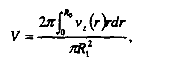
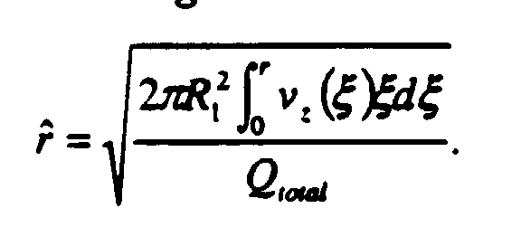
- the new location r ⁇ can be determined by performing a mass balance on the fluid flowing within the region 0 ⁇ ⁇ ⁇ r in the diffusion zone and equating this to the amount of mass flowing within a cylinder of radius r ⁇ moving at the plug flow velocity V(z) Integrating the left-hand-side of Eq. (13) and substituting the value of V(z) from Eq.
- Eq. (14) allows the calculation of the dopant profile rearrangement that occurs because of the rearrangement of the velocity field. For example, to determine the dopant mass-fraction field in the final extruded and drawn fiber from a given profile at an axial location Z within the diffusion zone, the following relation applies where superscript "final" indicates correspondence to the profile of the drawn fiber. Eq. (15) is useful for determining the degree of diffusion that occurs for various diffusion zone lengths.
- the steady-state, convection-diffusion problem defined by Eqs. (1), (3) and (4) with boundary conditions (5)-(11) is solved using a finite-element analysis that combines features from previous algorithms: a mixed finite-element method for discretizing the equations and boundary conditions, and local mesh refinement for computing accurate solutions near the diffusion front between the core and cladding materials.
- the finite-element formulation is based on the formulation of Rajagopalan et al., "Finite element methods for calculation of steady, viscoelastic flow using constitutive equations with a Newtonian viscosity, 11 J. Non-Newt. Fluid Mech. , Vol. 36, 159 (1990).
- the method is based on mixed-order, Lagrangian polynominal interpolations for the velocity and pressure fields that satisfy the compatibility condition for Stokes flow in confined domains discretized by quadrilateral isoparameteric finite elements.
- the finite-element approximations for the velocity and pressure fields are denoted as ( v h , p h ) where the superscript h denotes the dependence of the approximation on the characteristic mesh size h .
- the finite-element approximation to the velocity field is constructed in the space of functions with square-integrable first derivatives such that the no-penetration condition on the diffusion-zone wall and centerline is automatically satisfied - this approximation space is referred to as V h .
- the pressure field is assumed to be square-integrable, and the approximation space is written as P h .
- the tangential component of the velocity field is set as an essential boundary condition along the inflow ⁇ D i .
- the normal-velocity component is determined by solving a decoupled one-dimensional flow problem along the inflow where the solution satisfies the total flow rate constraint, eq. (6).
- the tangential components of velocity along the outflow and the diffusion-zone wall are set as essential conditions.
- the remaining boundary condition for the flow is the normal stress condition at the outflow. This condition is incorporated by rewriting the normal stress in components Along the outflow boundary, Eq. (18) becomes
- the mass-fraction field is constructed in the space of functions with square-integrable first derivatives, denoted as W h .
- the weak form of the dopant diffusion equation is written as ⁇ h ⁇ W h .
- a stabilized method such as the streamlined-upwind Petrov-Galerkin (SUPG) method may be required to discretize the dopant mass fraction equation (see A. N. Brooks and T. J. R. Hughes, Comp. Meth. Appl. Mech. Eng. , Vol. 32, 199 (1982)).
- SUPG streamlined-upwind Petrov-Galerkin
- C ( r ,0) C 0 1 2 - 1 2 tanh r - R core b .
- the coefficient b scales the width of the interfacial region at the inlet.
- the value of b is 2 x 10 -4 cm, or approximately 1/1000 th of the diffusion-zone radius for a 0.25 cm radius cylindrical diffusion zone.
- the step-index mass-fraction profile at the inlet is specified essentially, while the no-flux condition along the diffusion-zone wall and outflow is specified weakly through the line integral appearing in Eq. (20).
- Eqs. (16)-(20) are created by expressing the mass-fraction field and velocity components in expansions of Lagrangian biquadratic polynomials Q h / 2 constructed so that Q h / 2 ⁇ W h and Q h / 2 ⁇ V h , while the pressure field is written as an expansion of bilinear Lagrangian polynomials denoted by Q h / 1 ⁇ P h .
- These discretizations yield a large set of non-linear algebraic equations that are solved by Newton's method.
- the components of the Jacobian matrix are computed in closed form and the resulting linear equation set is solved by direct LU factorization by using frontal matrix methods (see P. Hood, "Frontal solution program for unsymmetric matrices, 11 Int. J. Numer. Meth. Eng. , Vol. 10, 379 (1976)).
- the finite-element algorithm makes use of local mesh refinement near the diffusion front between the core and the cladding materials.
- a mesh having 29,991 degrees of freedom for calculation of the velocity, pressure and mass-fraction fields for the diffusion-zone simulations is used for all of the calculations herein.
- the dopant was relatively low molecular weight (MW ⁇ 800) chlorotrifluoroethylene (CTFE) oligomer with a refractive index of approximately 1.41, as discussed in U.S. Patent No. 5,783,630. In the examples, the dopant was added to the core polymer at a level of 15 wt.%.
- the extrusion apparatus used to fabricate the GI-POF is shown in Fig. 12. (All surfaces in contact with the flowing melts were polished to promote smooth flow with little material stagnation. The machining of all parts was carried out with high precision to ensure a good fit, and thereby prevent leakage. Due to the corrosivity of the materials being processed, all tooling components were made from corrosion resistant materials, e.g., Hastelloy.) Solid granules of the doped core polymer and undoped cladding polymer were separately fed from hoppers into 1 ⁇ 2 inch, vertically mounted Randcastle model RCP 0500 extruders. Both extruders had corrosion-resistant barrels and screws for processing fluoropolymers.
- the extruders each had controlled heating zones and precise drives for control of screw RPM. They were capable of delivering homogeneous controlled temperature melt streams at constant flow rate and pressure to the dual extrusion head through a heated connector hose (for the core material) and a cylindrical joint (for the cladding material).
- the coextrusion head was designed to distribute the annular cladding melt stream around the central core melt stream in a smooth, laminar flow with no disruption of the interface between them.
- the joined streams coflowed axially in a tubular diffusion section of 5 mm inner diameter.
- the molten core material was introduced into the center of the crosshead assembly via a core tube 2, which included a gradually tapered (5°) internal cross section followed by a long, straight section of constant cross sectional area.
- the tapered region provided a transition in cross sectional area for the molten core material to flow from an extruder output nozzle to the smaller diameter required at the point the core and cladding materials are brought together.
- the inner diameter of the exit end of the core tube 2 was advantageously held at about 40% of the channel diameter in the die holder 5, just downstream, where the core and cladding materials are joined. This arrangement allowed the relative diameters of the core and cladding material streams to be controlled over wide ranges by simply varying the rate at which the individual streams were fed into the crosshead.
- the external surface of the exit end of the core tube 2 was also tapered (10°) and formed the interior wall of the transition region that directs the cladding material to flow into the channel in the die holder 5, where the cladding material joins with the core material.
- the cladding material was introduced into the crosshead assembly via a channel in the crosshead housing 8, from which the cladding material flowed into a channel machined in the side of die holder 5.
- the material flowed upward and exited this channel to flow into distributing channels machined into the lower surface of core tube holder 3.
- the distributing channels assured a relatively uniform flow of cladding material around the tapered exterior of the core tube 2 by dividing the flow into four streams and introducing them into the tapered channel 90° apart. With this arrangement the core and cladding melt streams were joined together in a smooth regular manner, with very little, if any, disruption of the interface between the two materials or distortion of the concentric circular geometry of the core/cladding cross section.
- the diffusion sections 4 (only one shown) were threaded onto the die holder 5.
- the diffusion sections 4 had an inner diameter which matched that of the die holder.
- the sections 4 were modular and capable of being threaded together to provide a diffusion zone of desired length.
- the temperature of the section was controlled either by a series of band heaters or high temperature heating tapes, capable of independent control.
- the dopant in the core polymer had sufficient mobility in the high temperature molten polymer to diffuse radially under the influence of the concentration gradient present at the core/cladding interface.
- An exit die 6 was threaded onto the final diffusion section.
- the die had a 1.0 mm diameter straight land at the exit and a tapered inlet (10°) to transition the cross section from the diffusion section to the land.
- the GI-POF melt strand extruded from the die was drawn down to its desired diameter outside the die by pulling it at a controlled speed with a Heathway, Model HSM 048 capstan.
- a Model 910 LaserMike diameter monitor was positioned close to the die but beyond the drawdown region of the fiber to monitor the diameter. The fiber was taken up on a spool.
- a time equal to at least three times the average residence time of the material in the diffusion zone was allowed to elapse before taking a fiber sample for evaluation to ensure equilibrium of the profile.
- the refractive index profiles of the fiber samples were measured using a Leitz interference microscope via the transverse interferometric method (See D. Marcuse, Principles of Optical Fiber Measurement , Academic Press, New York, 1981, pp. 150-161.)
- a solution of water and propylene glycol in the weight ratio 92.2 to 7.8 was used to match the refractive index of the perfluorinated GI-POF cladding (1.340) for the measurement.
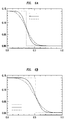
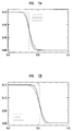
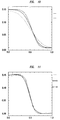
- the refractive index profiles of Figs. 2-5 show the local refractive index increase from the index of the undoped CYTOPTM plotted against radial position normalized by the fiber radius.
- Example 1 RPM ratio of core/cladding extruders
- the core extruder was run with a temperature profile that resulted in a melt temperature at the output to the co-extrusion crosshead of 190°C.
- the cladding extruder temperature profile was set to deliver melt at 220°C.
- the crosshead temperature was set at 220°C and the temperature of the one meter long diffusion zone was set at 250°C.
- the combined (total) output of the extruders was about 6 grams (3 cm 3 ) per minute. For a 250 ⁇ m diameter fiber, this output corresponded to a production rate of 1 meter per second.
- the first was made with a core extruder rpm of 2.7 and a cladding extruder rpm of 22.5 resulting in a core-to-cladding rpm ratio of 0.12 with an output of 6.2 grams per minute.
- the second fiber was made with a core extruder rpm of 4.0 , a cladding extruder rpm of 22.5 resulting in a ratio of 0.18 with an output of 5.6 grams per minute.
- the core extruder rpm was 5.0, the cladding extruder rpm 22.5 resulting in a ratio of 0.22 and a total output of 5.6 grams per minute.
- the fourth fiber had the core extruder rpm set at 6.4, the cladding extruder rpm set at 22.5 resulting in a ratio of 0.28 with an output of 5.9 grams per minute.
- the core extruder rpm was 0.75, the cladding extruder rpm was 3.75 and the total output was 1.25 grams per minute.
- the core extruder rpm was 1.5, the cladding extruder rpm was 7.5 and the total output was 3.0 grams per minute.
- the core extruder rpm was 4.0 and the cladding extruder rpm was 22.5 and the total output was 5.6 grams per minute, this last output rate corresponding to a production rate of 0.95 m/sec for a 250 ⁇ m diameter fiber.
- comparison of the three profiles shows that as the diffusion zone length is increased the refractive index gradient at the boundary between the core and cladding is reduced and made more gradual owing to the diffusion that occurs as the core and cladding polymers co-flow through the diffusion section.
- the crosshead temperature was set at 220°C.
- the temperature of the core melt entering the crosshead was set at 190°C.
- the temperature of the cladding material entering the crosshead was 220°C.
- the diffusion zone length was one meter, the output rate was approximately 6 grams/minute and the ratio of the core to cladding extruder screw rpm was held at 0.32 for all runs.
- the diffusion zone temperature was set at 230°C
- the cladding extruder rpm was 10.6
- the core extruder rpm was 3.4 which resulted in an output rate of 6.2 grams per minute.
- the diffusion zone temperature was set at 270°C
- the individual core and cladding extruder rpm's were set at 3.2 and 10, respectively, keeping the ratio at 0.32 with an output of 5.9 grams/minute.
- the profile for the fiber made at the low diffusion zone temperature shows a flat refractive index region in the center of the core and a relatively steep gradient at the core-cladding transition.
- the fiber made with the diffusion zone temperature of 270°C shows rounding of the profile in the center of the core and a more gradual index gradient at the core-cladding boundary.
- the value of Q total for this Example corresponds to making 300 micron diameter fiber at a production speed of 1 m/s or 250 micron diameter fiber at a speed of 1.4 m/s.
- the diffusion front separating these materials widens, indicating diffusion of the dopant into the cladding region.
- the dopant mass-fraction field is plotted as a function of normalized radius in Fig. 6A at different axial locations, z , within the diffusion zone.
- the profile diffuses away from the step-index profile at the inlet and towards a more smoothly varying profile.
- the profile at a distance of 100 cm into the diffusion zone exhibits significantly more diffusion of the dopant into the cladding region than at 50 cm.
- Fig. 6B the mapped profile reflecting this rearrangement, given by Eq. 15, is plotted in Fig. 6B as a function of normalized radius.
- the effect of the flow rearrangement on the final dopant profile is evident from the differences between Figs. 6A and 6B.
- the dopant mass-fraction field is plotted as a function of normalized radius in Fig. 7A at different axial positions within the diffusion zone. As the dopant material progresses through the diffusion zone, the profile gradually develops into a more parabolic-like profile. Contrasting Figs. 7A and 6A shows that reduced temperatures result in a less diffuse mass-fraction profile. These results indicate that at lower temperatures a diffusion zone greater than 100 cm in length would be required to achieve the same level of diffusion as at 300°C.
- Fig. 7B the mapped profile, given by Eq. 15, is plotted in Fig. 7B as a function of normalized radius. The significance of the flow rearrangement on the final dopant profile is evident from a comparison of Figs. 7A and 7B.
- Q total 0.0353, 0.0707 and 0.106 cm 3 /sec
- a potential source of impurities in GI-POF is degradation of the dopant and/or polymer due to lengthy exposure to high temperatures.
- the average residence time within the diffusion zone is determined from the formula Note that the average residence time scales with the square of the diffusion-section radius, so that doubling the diffusion-section radius results in a factor of 4 increase in avenge residence time. Reducing thermal exposure times requires that one reduce the diffusion-section radius to as small a value as is acceptable. Note that the results of the previous Example show that there are restrictions on the minimum allowable radius due to the generation of large pressure gradients across the diffusion zone.
- the average residence time is proportional to the ratio L/Q total (where L is diffusion zone length). Physical considerations suggest that this quantity should remain a constant for a given dopant profile, i.e., doubling of the flow rate will require a doubling of the diffusion-zone length to achieve the same dopant profile.
- T oper 300°C R 0 (cm) 0.1 0.25 0.5 0.1 0.25 0.5 ⁇ (s) 176 1,111 4,444 44 278 1,111
- Example 10 shows that a larger diffusion section radius is beneficial for lowering the total pressure drop across the diffusion zone, the quadratic increase in residence time with radius shown in this Example 11 suggests operating with as small a diffusion-section radius as possible to reduce thermal exposure.
- a diffusion section radius of R 0 0.25 cm appears to be an adequate compromise between these two conflicting criteria.
- Example 13 Design of Diffusion Section for Manufacture of GI-POF at High Rates
- Pe L min the dopant profile tends to be too diffuse, and above Pe L max , the dopant profile tends to be too step-like.
- Pe L min is about 10
- Pe L max is about 500. See, e.g., Fig. 13, which shows a predicted dopant mass fraction profile (vs. normalized radius), for a variety of Pe values.
- the necessary length of the diffusion section is able to be determined from eq. 24 by substituting values for Pe L , Q total (proportional to the desired fiber production rate) and D.
- the second parameter that requires specification is the radius of the diffusion section R 0 .
- a minimum value for this parameter is able to be determined by specifying the maximum allowable pressure drop across the diffusion section, ⁇ P max .
- ⁇ P max the maximum allowable pressure drop across the diffusion section
- ⁇ P max the maximum allowable pressure drop across the diffusion section
- R 0 min the minimum allowable radius of the diffusion section
- R 0 min [ ⁇ clad L Q total / ⁇ P max ] 1 ⁇ 4 .
- the minimum radius, R 0 min , along with the diffusion section length, L, and the total flow rate, Q total it is possible to calculate the minimum residence time for the polymers in the diffusion section from eq. 21. It is then possible to make a decision as to whether this residence time is acceptable based on the thermal stability of the polymers and dopants.
- the maximum fiber production rate is able to be determined by the maximum residence time allowable at the processing temperature.
- equations 24 and 28 allow specification of the diffusion zone length and minimum diffusion section radius for given values of the fiber production rate, extent of diffusion and material properties, ⁇ clad , and D.
- This approach of the invention provides a pathway for scaling up the extrusion process to higher production rates.
Landscapes
- Engineering & Computer Science (AREA)
- Mechanical Engineering (AREA)
- Manufacturing & Machinery (AREA)
- Health & Medical Sciences (AREA)
- Ophthalmology & Optometry (AREA)
- Physics & Mathematics (AREA)
- General Physics & Mathematics (AREA)
- Optics & Photonics (AREA)
- Extrusion Moulding Of Plastics Or The Like (AREA)
- Optical Fibers, Optical Fiber Cores, And Optical Fiber Bundles (AREA)
Abstract
Description
The functional form D 0 (T) is represented by


The viscosity η is assumed to be dependent upon temperature, dopant mass fraction and shear rate γ ˙:




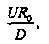









| Toper = 250°C | Toper = 300°C | |||||
| R0(cm) | 0.1 | 0.25 | 0.5 | 0.1 | 0.25 | 0.5 |
| | 176 | 1,111 | 4,444 | 44 | 278 | 1,111 |
Claims (26)
- A process for fabricating graded index plastic optical fiber, comprising the steps of:introducing a first polymer material into a first nozzle;introducing a second polymer material into a second nozzle concentrically located around the first nozzle, wherein at least one of the first polymer material and the second polymer material comprises at least one refractive index-altering diffusible dopant;directing the first and second polymer materials from the first and second nozzles into a diffusion section in a concentric manner such that diffusion of the dopant is possible between and within the first and second polymer materials, wherein the materials flow through a diffusion zone having a length of at least 33 cm, and wherein the diffusion zone temperature is at least 50°C above the higher of the glass transition temperature of the first polymer material and the glass transition temperature of the second polymer material;extruding the first and second polymer materials from the diffusion section through an exit die at a flow rate of at least 0.5 cm3/min; anddrawing the materials from the exit die to form the optical fiber.
- The process of claim 1, wherein the diffusion zone length is about 50 to about 400 cm.
- The process of claim 1, wherein the diffusion section is tubular and the average diameter of the diffusion section is about 0.25 cm to about 2 cm.
- The process of claim 3, wherein the diffusion section has an average diameter of about 0.50 cm.
- The process of claim 1, wherein the residence time of the first and second polymer materials in the diffusion zone is about 1 minute to about 120 minutes.
- The process of claim 1, wherein the resultant fiber has an outer diameter of about 125 µm to about 1000 µm.
- The process of claim 6, wherein the fiber production rate is at least 0.5 meter per second.
- The process of claim 7, wherein the fiber production rate is at least 1 meter per second.
- The process of claim 1, wherein the first and second polymer materials are the same, wherein the first polymer material comprises the dopant, and wherein the dopant has a refractive index greater than the refractive index of the first and second polymer materials.
- The process of claim 1, wherein at least one of the first and the second polymer materials comprises at least two refractive index-altering diffusible dopants.
- The process of claim 1, wherein distinct temperature zones are provided over the diffusion zone length.
- The process of claim 1, wherein the second polymer material comprises the at least one dopant.
- The process of claim 1, wherein PeL is between 10 and 500.
- A process for fabricating graded index plastic optical fiber, comprising the steps of:introducing a first polymer material into a first nozzle;introducing a second polymer material into a second nozzle concentrically located around the first nozzle, wherein at least one of the first polymer material and the second polymer material comprises at least one refractive index-altering diffusible dopant;directing the first and second polymer materials from the first and second nozzles into a diffusion section in a concentric manner such that diffusion of the dopant is possible between and within the first and second polymer materials;extruding the first and second polymer materials from the diffusion section through an exit die; anddrawing the polymer materials from the exit die to form the optical fiber,
wherein parameters of the process are selected based on a predicted dopant or refractive index profile obtained by:(a) providing values for process and material characteristics comprising diffusion zone length, diffusion zone radius, dopant diffusivity in the first and the second polymer materials, and flow rate of the first and the second polymer materials;(b) performing a numerical analysis using the values to calculate the predicted dopant or refractive index profile; and(c) optionally repeating steps (a) and (b). - The process of claim 14, wherein the process and material characteristics further comprise at least one of density of the dopant/polymer system, viscosity of the dopant/polymer system, and temperature of the diffusion section.
- The process of claim 14, wherein the numerical analysis comprises a mixed finite element method for discretizing equations and boundary conditions and a local mesh refinement for computing solutions near the diffusion front between the first and the second polymer materials.
- The process of claim 14, wherein the provided value for diffusion zone length is about 33 cm to about 400 cm, the provided value for diffusion zone radius is about 0.25 to about 2 cm, the provided values for diffusivity are about 1 x 10⁻⁸ to about 1 x 10⁻⁵ cm2/sec, and the provided value for flow rate is about 0.5 to about 15 cm3/min.
- The process of claim 15, wherein the value for viscosity is about 1000 to about 100,000 poise.
- The process of claim 14, wherein the residence time of the first and second polymer materials in the diffusion zone is about 1 minute to about 120 minutes.
- The process of claim 14, wherein the resultant fiber has an outer diameter of about 125 µm to about 1000 µm.
- The process of claim 20, wherein the fiber production rate is at least 1 meter per second.
- The process of claim 14, wherein the first and second polymer materials are the same, wherein the first polymer material comprises the dopant, and wherein the dopant has a refractive index greater than the refractive index of the first and second polymer materials.
- The process of claim 14, wherein at least one of the first and the second polymer materials comprises at least two refractive index-altering diffusible dopants.
- The process of claim 14, wherein the distinct temperature zones are provided over the diffusion zone length.
- The process of claim 14, wherein second polymer material comprises the at least one dopant.
- The process of claim 14, wherein PeL is between 10 and 500.
Applications Claiming Priority (2)
| Application Number | Priority Date | Filing Date | Title |
|---|---|---|---|
| US321050 | 1989-03-09 | ||
| US09/321,050 US6254808B1 (en) | 1999-05-27 | 1999-05-27 | Process for fabricating plastic optical fiber |
Publications (2)
| Publication Number | Publication Date |
|---|---|
| EP1057617A2 true EP1057617A2 (en) | 2000-12-06 |
| EP1057617A3 EP1057617A3 (en) | 2003-01-29 |
Family
ID=23248970
Family Applications (1)
| Application Number | Title | Priority Date | Filing Date |
|---|---|---|---|
| EP00304068A Withdrawn EP1057617A3 (en) | 1999-05-27 | 2000-05-15 | Process for fabricating plastic optical fiber |
Country Status (8)
| Country | Link |
|---|---|
| US (1) | US6254808B1 (en) |
| EP (1) | EP1057617A3 (en) |
| JP (1) | JP2000356716A (en) |
| KR (1) | KR20010066805A (en) |
| CN (1) | CN1275479A (en) |
| AU (1) | AU3535900A (en) |
| BR (1) | BR0002427A (en) |
| CA (1) | CA2308661A1 (en) |
Cited By (2)
| Publication number | Priority date | Publication date | Assignee | Title |
|---|---|---|---|---|
| WO2003066715A1 (en) * | 2002-02-07 | 2003-08-14 | Photon-X, Inc. | Nanoporous random glassy polymers |
| EP1536255A1 (en) * | 2003-11-26 | 2005-06-01 | Samsung Electronics Co., Ltd. | Apparatus and method for fabricating plastic optical fiber |
Families Citing this family (19)
| Publication number | Priority date | Publication date | Assignee | Title |
|---|---|---|---|---|
| EP1272336A2 (en) * | 2000-04-12 | 2003-01-08 | Nanoptics, Inc. | Method and apparatus for manufacturing plastic optical transmission medium |
| US7045010B2 (en) * | 2001-09-06 | 2006-05-16 | Alcatel | Applicator for high-speed gel buffering of flextube optical fiber bundles |
| EP1472073A1 (en) * | 2001-12-31 | 2004-11-03 | General Components Inc. | Optical fiber production system and crosshead die therefor |
| US6859600B2 (en) * | 2002-05-30 | 2005-02-22 | Alcatel | Coated optical fiber and optical fiber ribbon and method for the fabrication thereof |
| US6861148B2 (en) * | 2002-11-22 | 2005-03-01 | Chromis Fiberoptics, Llc | Plastic optical fiber preform |
| US20050157999A1 (en) * | 2002-12-27 | 2005-07-21 | Zhen Zhen | Graded index polymer optical fiber and a method of making the same |
| ATE346316T1 (en) * | 2003-02-10 | 2006-12-15 | Nanoptics Inc | METHOD AND APPARATUS FOR PRODUCING OPTICAL TRANSMISSION MEDIA |
| US20040251567A1 (en) * | 2003-06-13 | 2004-12-16 | Pierluigi Cappellini | Method and system for producing plastic optical fiber |
| US20040264899A1 (en) * | 2003-06-13 | 2004-12-30 | Peterson James F. | Flat plastic optical fiber and illumination apparatus using such fiber |
| US20050056952A1 (en) * | 2003-09-15 | 2005-03-17 | Walker James K. | Method of manufacturing multi-polymer optical fiber cable |
| WO2005103774A1 (en) * | 2004-04-22 | 2005-11-03 | Lite-On Japan Ltd. | Production method for graded index type optical transmission element |
| JP2006208551A (en) * | 2005-01-26 | 2006-08-10 | Fuji Photo Film Co Ltd | Method and equipment for manufacturing plastic optical fiber |
| EP2896977B1 (en) | 2012-09-11 | 2017-08-16 | Asahi Glass Company, Limited | Plastic optical fiber and method for its production |
| CN103963257B (en) * | 2014-04-03 | 2015-12-30 | 江苏长飞中利光纤光缆有限公司 | Method for manufacturing optical fiber protection hollow tube |
| CN107234790A (en) * | 2017-06-22 | 2017-10-10 | 江苏亨通光电股份有限公司 | Exempt from form removal in tight tube fiber extruding production technology to wear the method for fibre and exempt to tear frock open |
| US11009662B2 (en) * | 2017-09-05 | 2021-05-18 | Facebook Technologies, Llc | Manufacturing a graded index profile for waveguide display applications |
| DE102018124175A1 (en) * | 2018-10-01 | 2020-04-02 | Sikora Ag | Method and device for controlling a production plant for plate-like or strand-like bodies |
| CN115668015A (en) * | 2020-05-29 | 2023-01-31 | 日东电工株式会社 | Method for producing resin molded body for optical use, method for producing resin fiber, and apparatus for producing resin fiber |
| CN116408952B (en) * | 2023-04-20 | 2025-09-19 | 中国科学院西安光学精密机械研究所 | Preparation method of large-size gradient refractive index type plastic optical fiber preform |
Family Cites Families (13)
| Publication number | Priority date | Publication date | Assignee | Title |
|---|---|---|---|---|
| EP0004183B1 (en) * | 1978-03-14 | 1981-09-16 | The Post Office | Method and apparatus for drawing optical fibres by means of a double crucible |
| US5235660A (en) * | 1992-07-10 | 1993-08-10 | Peachtree Fiberoptics, Inc. | Graded polymer optical fibers and process for the manufacture thereof |
| US5593621A (en) | 1992-08-17 | 1997-01-14 | Koike; Yasuhiro | Method of manufacturing plastic optical transmission medium |
| US5496913A (en) | 1992-11-02 | 1996-03-05 | Furukawa Electric Co., Ltd | Aromatic polycarbonate, a method for producing the same, and a plastic optical waveguide using the same |
| US5614253A (en) | 1993-06-16 | 1997-03-25 | Sumitomo Electric Industries, Ltd. | Plastic optical fiber preform, and process and apparatus for producing the same |
| US5639512A (en) | 1993-06-18 | 1997-06-17 | Sumitomo Electric Industries, Ltd. | Plastic optical fiber preform, and process and apparatus for producing the same |
| JPH07276434A (en) * | 1994-04-08 | 1995-10-24 | Sekisui Chem Co Ltd | Injection molding equipment |
| US5783636A (en) | 1994-04-18 | 1998-07-21 | Yasuhiro Koike | Graded-refractive-index optical plastic material and method for its production |
| US5760139A (en) | 1994-04-18 | 1998-06-02 | Yasuhiro Koike | Graded-refractive-index optical plastic material and method for its production |
| US5555525A (en) * | 1994-09-07 | 1996-09-10 | Industrial Technology Research Institute | Method of making graded refractive index polymeric optical fibers and optical fibers made by the method |
| US6106745A (en) * | 1995-11-30 | 2000-08-22 | Akzo Nobel Nv | Method of making graded index polymeric optical fibers |
| CN1101000C (en) * | 1996-03-28 | 2003-02-05 | 三菱丽阳株式会社 | Distributed refractive index type optical fiber and its manufacturing method and multi-core optical fiber with sea-island structure |
| US5729645A (en) | 1996-08-13 | 1998-03-17 | The Trustees Of The University Of Pennsylvania | Graded index optical fibers |
-
1999
- 1999-05-27 US US09/321,050 patent/US6254808B1/en not_active Expired - Lifetime
-
2000
- 2000-05-15 EP EP00304068A patent/EP1057617A3/en not_active Withdrawn
- 2000-05-17 CA CA002308661A patent/CA2308661A1/en not_active Abandoned
- 2000-05-17 AU AU35359/00A patent/AU3535900A/en not_active Abandoned
- 2000-05-18 BR BR0002427-9A patent/BR0002427A/en not_active IP Right Cessation
- 2000-05-23 JP JP2000151547A patent/JP2000356716A/en not_active Abandoned
- 2000-05-25 CN CN00117903A patent/CN1275479A/en active Pending
- 2000-05-27 KR KR1020000028829A patent/KR20010066805A/en not_active Ceased
Cited By (2)
| Publication number | Priority date | Publication date | Assignee | Title |
|---|---|---|---|---|
| WO2003066715A1 (en) * | 2002-02-07 | 2003-08-14 | Photon-X, Inc. | Nanoporous random glassy polymers |
| EP1536255A1 (en) * | 2003-11-26 | 2005-06-01 | Samsung Electronics Co., Ltd. | Apparatus and method for fabricating plastic optical fiber |
Also Published As
| Publication number | Publication date |
|---|---|
| US6254808B1 (en) | 2001-07-03 |
| EP1057617A3 (en) | 2003-01-29 |
| JP2000356716A (en) | 2000-12-26 |
| CA2308661A1 (en) | 2000-11-27 |
| BR0002427A (en) | 2001-01-02 |
| KR20010066805A (en) | 2001-07-11 |
| AU3535900A (en) | 2000-11-30 |
| CN1275479A (en) | 2000-12-06 |
Similar Documents
| Publication | Publication Date | Title |
|---|---|---|
| US6254808B1 (en) | Process for fabricating plastic optical fiber | |
| US20010037663A1 (en) | Methods for producing optical fiber by focusing high viscosity liquid | |
| Evertz et al. | Dip coating of thin polymer optical fibers | |
| Miller et al. | Control of the sharkskin instability in the extrusion of polymer melts using induced temperature gradients | |
| JP5701302B2 (en) | Non-cylindrical filaments used in extrusion digital manufacturing systems | |
| US6527986B2 (en) | Extrusion process for fabricating plastic optical fiber | |
| Pone et al. | Drawing of the hollow all-polymer Bragg fibers | |
| JPH02501913A (en) | Hollow optical transmission body and its manufacturing method and manufacturing device | |
| US6199257B1 (en) | Method of making a flow cell for light absorption measurement of small volume samples | |
| US20190275704A1 (en) | Method and device for forming microstructured fibre | |
| Xue et al. | Fabrication of microstructured optical fibers-Part II: Numerical modeling of steady-state draw process | |
| Ren et al. | Experimental and numerical studies for the gas-assisted extrusion forming of polypropylene micro-tube | |
| Jin et al. | Cross-section design of multi-lumen extrusion dies: Study on the effects of die swell and gas flow rate of the lumen | |
| JPH02501912A (en) | Polymer optical waveguide, method and apparatus for producing same by coextrusion | |
| Arda et al. | Sharkskin instabilities and the effect of slip from gas-assisted extrusion | |
| Yu et al. | Process analysis of coc terahertz fiber fabrication by one-step extrusion | |
| CN116330609B (en) | Layered co-extrusion molds and production equipment for manufacturing polymer optical fibers | |
| CN220429189U (en) | Layered coextrusion die for manufacturing polymer optical fiber and production equipment | |
| Jaluria | Manufacture of optical fibers: drawing and coating processes | |
| CA1170876A (en) | Fiber with coarse index gradient | |
| Sohn et al. | Novel method for the fabrication of gradient‐index plastic optical fibers | |
| Puissant | Extrusion of Cables | |
| JP2005516791A (en) | Optical fiber manufacturing system and crosshead die therefor | |
| WO1991000798A1 (en) | Finishing process for extruded profiles | |
| Yurygin et al. | Features in the Evolution of a Two-Layer Flow of Rubber Mixtures at the Exit from a Die |
Legal Events
| Date | Code | Title | Description |
|---|---|---|---|
| PUAI | Public reference made under article 153(3) epc to a published international application that has entered the european phase |
Free format text: ORIGINAL CODE: 0009012 |
|
| 17P | Request for examination filed |
Effective date: 20000525 |
|
| AK | Designated contracting states |
Kind code of ref document: A2 Designated state(s): AT BE CH CY DE DK ES FI FR GB GR IE IT LI LU MC NL PT SE |
|
| AX | Request for extension of the european patent |
Free format text: AL;LT;LV;MK;RO;SI |
|
| PUAL | Search report despatched |
Free format text: ORIGINAL CODE: 0009013 |
|
| AK | Designated contracting states |
Designated state(s): AT BE CH CY DE DK ES FI FR GB GR IE IT LI LU MC NL PT SE |
|
| AX | Request for extension of the european patent |
Extension state: AL LT LV MK RO SI |
|
| 17Q | First examination report despatched |
Effective date: 20030218 |
|
| AKX | Designation fees paid |
Designated state(s): DE FR GB |
|
| STAA | Information on the status of an ep patent application or granted ep patent |
Free format text: STATUS: THE APPLICATION HAS BEEN WITHDRAWN |
|
| 18W | Application withdrawn |
Effective date: 20031223 |