Background of the Invention
Field of the Invention
The present invention relates to an apparatus for taking out
a molded product by letting the retaining mechanism unit for
retaining a molded product penetrate between the die halves after
die opening, for instance, in an injection molding machine.
Disclosure of the Prior Art
The basic operation of an injection molding machine of the
above type is as follows. Resin is injected into a mold cavity
subsequently to clamping of the die halves and after the resin has
been cooled, the die halves are opened. Thereafter, a molded
product is taken out by a take-out apparatus such as a product
take-out robot and then, the die halves are again clamped. Such
an operation is repeatedly carried out.
Take-out of a molded product is performed by a take-out
apparatus for a molded product, which has a retaining mechanism
unit for retaining a molded product and a moving mechanism unit
for moving the retaining mechanism unit.
The take-out operation of the take-out apparatus for a molded
product is carried out in the way shown in FIGURE 6. Specifically,
after die opening, the retaining mechanism unit which has been
stopping at a waiting position (A) penetrates to an penetrating
position (B) within the die halves. Then, the retaining mechanism
unit moves toward a take-out position (C) and stops upon arrival
at the take-out position (C) (1 ○ penetration process). At the
take-out position (C), the retaining mechanism unit retains the
molded product which has been separated from a die half (2 ○ take-out
process). The retaining mechanism unit with the molded product
retained moves back to a specified pulling out position (D) from
the take-out position (C). After moving to a withdrawing position
(E) (3 ○ withdrawal process), the retaining mechanism unit moves
from the withdrawing position (E) to a retrieving position (F) where
it liberates the molded product and when reaching the retrieving
position (F), the retaining mechanism unit stops (4 ○ conveyance
process). At the retrieving position (F), the molded product is
released from holding by the retaining mechanism unit so that the
molded product can be retrieved (5 ○ liberation process). Upon
completion of liberating the molded product at the retrieving
position (F), the retaining mechanism unit returns from the
retrieving position (F) to the waiting position (A) (6 ○ return
process) where the retaining mechanism unit waits until the next
take-out operation for a molded product starts (7 ○ waiting process).
A time chart for the above processes (see FIGURE 7) is
constituted by the penetration/withdrawal time Tae (FIGURE 7(a))
which is required for the penetration process and the withdrawal
process; the conveyance time Tef (FIGURE 7(b)) required for the
conveyance process; the molded product liberation time Tf (FIGURE
7(c)) required for liberation at the retrieving position (F); the
return time Tfa (FIGURE 7(d)) required for the return process and
the wait time Ta (FIGURE 7(e)) required for waiting at the waiting
position (A).
Conventionally, in the return process in which the retaining
mechanism unit which has liberated the molded product returns from
the retrieving position (F) to the initial waiting position (A),
the returning operation is set by the operator such that the
retaining mechanism unit can move as fast as possible. This is
because a sufficient wait time is ensured for the retaining
mechanism unit when waiting at the waiting position (A) in order
that the retaining mechanism unit should penetrate between the die
halves immediately after completion of the next die opening thereby
executing the penetration process without fail. For completing
the return process quickly, it is necessary to increase the moving
speed of the retaining mechanism unit, which involves rapid
acceleration and rapid deceleration. The moving mechanism unit
is therefore activated abruptly, entailing strong impact on the
moving mechanism unit. As a result, there arise the problems of
damage to the mechanical parts at an early stage and increased
electric power consumption.
Summary of the Invention
A prime object of the invention is to reduce damage to the
mechanical parts of a moving mechanism unit and electric power
consumption in an apparatus for taking out a molded product, the
apparatus comprising a retaining mechanism unit for retaining a
molded product and a moving mechanism unit for moving the retaining
mechanism unit, the apparatus being designed such that the retaining
mechanism unit penetrates between die halves from a specified waiting
position after die opening to take out the molded product and the
molded product is liberated at a specified retrieving position which
is located outside the die halves.
The above object can be accomplished by an apparatus for taking
out a molded product constructed according to the invention, the
apparatus comprising:
The above technical means functions in the following way.
In the molded product take-out operation of the preceding
process (i.e., initializing operation) which is firstly carried
out, the retaining mechanism unit which has liberated the molded
product at the retrieving position is moved from the retrieving
position to the waiting position by carrying out returning operation
with the moving mechanism unit, and the retaining mechanism unit
temporarily stops and waits at the waiting position until completion
of die opening. At that time, the return time taken for the returning
operation and the wait time at the waiting position are measured
by the time measuring means, and then, a return moving speed
distribution which allows the returning operation to be carried
out within the measured return time is calculated by the arithmetic
means. The moving speed in the return moving speed distribution
calculated herein includes the wait time for the preceding process
so that the moving speed can be made slower than that of the
conventional system in which await time is assured. In consequence,
moderate acceleration and deceleration can be carried out in the
invention. In the returning operation in the succeeding process
which takes place after the preceding process, wait time
substantially vanishes because the moving mechanism unit is
activated based on an instruction from the controlling means
according to the return moving speed distribution calculated by
the arithmetic means, so that the activation of the moving mechanism
unit at that time can be performed at a moderate speed.
The invention is designed as described above and therefore
exerts the following effects.
In the apparatus for taking out a molded product according
to the invention, the retaining mechanism unit is arranged such
that its moving speed in returning operation is reduced thereby
moderating acceleration and deceleration to slowly activate the
moving mechanism unit, whereby damage to the mechanical parts of
the moving mechanism unit and electric power consumption can be
restricted. In consequence, the service life of the apparatus can
be prolonged and the cost of electric power consumption can be
reduced.
The above object can be also achieved by the arrangement
wherein: the retaining mechanism unit takes the molded product
out of the die halves and performs conveying operation in which
the molded product is conveyed from a specified withdrawing position
located outside the die halves to the retrieving position;
Other objects, features, aspects and advantages of the
invention will become more apparent from the following detailed
description of embodiments with reference to the accompanying
drawings and claims.
Brief Description of the Drawings
FIGURE 1 is a block diagram showing the structure of an
apparatus for taking out a molded product according a first embodiment
of the invention.
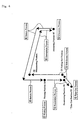
FIGURE 2 is a flow chart of an initializing operation for
setting a return moving speed distribution for a return process.
FIGURE 3 is a table for showing a speed distribution used
for calculating a return moving speed.
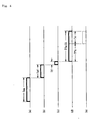
FIGURE 4 is a time chart of a take-out operation performed
at the calculated return moving speed.
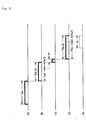
FIGURE 5 is a time chart of a take-out operation performed
at the calculated return moving speed according to a second
embodiment.
FIGURE 6 is an operation chart showing the basic actions of
the take-out operation of the apparatus for taking out a molded
product.
FIGURE 7 is a time chart of a take-out operation in a prior
art take-out apparatus.
Detailed Description of the Embodiments
Referring now to the drawings, a first embodiment of the
invention will be hereinafter described.
[First Embodiment]
FIGURE 1 is a block diagram showing the structure of an
apparatus for taking out a molded product constructed according
to the first embodiment of the invention. Referring to FIGURE 1,
the molded product take-out apparatus of the first embodiment
comprises a retaining mechanism unit 7 for taking a molded product
out of die halves and a moving mechanism unit 5 for moving the
retaining mechanism unit 7. It further comprises a time measuring
unit 4, a position detecting unit 6 and a CPU (Central Processing
Unit) 1.
Although not shown in the drawings, the retaining mechanism
unit 7 is composed of a take-out arm and a take-out head attached
to the distal end of the take-out arm. By means of the take-out
head, a molded product is retained by adsorption, chucking or
clamping. The proximal end of the take-out arm is connected to
the moving mechanism unit 5.
The moving mechanism unit 5 includes a conveyance/return
mechanism 51 and a penetration/withdrawal mechanism 52.
In the first embodiment, the conveyance/return mechanism 51
allows the traversing movement of the retaining mechanism unit 7,
thereby performing conveying operation (conveyance process) for
conveyance from a withdrawing position (E) to a retrieving position
(F) (see FIGURE 6) and returning operation (return process) for
returning from the retrieving position (F) to a waiting position
(A). The penetration/withdrawal mechanism 52 allows the
ascending/descending movement of the retaining mechanism unit 7,
thereby performing penetrating operation (penetration process) for
penetration from the waiting position (A) to a take-out position
(C) and withdrawing operation (withdrawal process) for withdrawal
from the take-out position (C) to the withdrawing position (E).
The position detecting unit 6 detects the movement position
of the retaining mechanism unit 7 based on the driving amount of
the moving mechanism unit 5, and it is determined whether the
retaining mechanism unit 7 has reached each of the waiting position
(A), the penetrating position (B), the take-out position (C), the
pulling out position (D), the withdrawing position (E) and the
retrieving position (F).
The time measuring unit 4 measures the return time elapsing
since a start of the return process in the preceding process (i.e.,
initializing operation) until a start of the penetration process
which is carried out subsequently to a completion of the waiting
process. This return time is measured by counting clock signals
sent from the CPU 1.
The CPU 1 controls the overall take-out apparatus based on
a program prestored in a ROM 2. The CPU 1 performs signal processing
to instruct activation of the moving mechanism unit 5, based on
a signal from a die clamping mechanism unit 81 in a molding machine
8, a positional detection signal from the position detecting unit
6 and data stored in a RAM 3. The CPU 1 has an arithmetic operation
unit 11 having a leaning function and the arithmetic operation
unit 11 calculates a return moving speed distribution which allows
the return process to be completed upon elapse of the return time
measured by the time measuring unit 4. The CPU 1 contains a control
unit 12 which activates the moving mechanism unit 5 such that the
return process in the process succeeding the preceding process is
performed according to the return moving speed distribution
calculated by the arithmetic operation unit 11. Since the moving
speed based on the return moving speed distribution calculated
herein includes the wait time of the preceding process, it can be
slower than the moving speed of the return process in the preceding
process in which a wait time is assured, so that moderate
acceleration and deceleration can be carried out.
Next, there will be explained the operation of the apparatus
for taking out a molded product according to the first embodiment
of the invention.
Referring to FIGURE 6, the basic operations (described
earlier) of the present take-out apparatus are carried out in the
following order: (1) penetration process (penetrating operation)
→ (2) take-out process (molded product retaining operation) →
(3) withdrawal process (withdrawing operation → 4) conveyance
process (conveying operation → (5) liberation process (liberating
operation) → (6)return process (returning operation) →(7) waiting
process. In (1) penetration process, (3) withdrawal process, (4)
conveyance process and (6) return process among the above processes,
the moving mechanism unit 5 is operated. The moving speed in each
process is so set beforehand by the operator that each process can
be finished in good time for starting the next molding cycle. The
return process is carried out quickly in order to perform the
penetration process in the next molding cycle without fail and
assures sufficient wait time in the waiting process. In the first
embodiment, the return process in the process succeeding the
preceding process (initializing operation) is performed by the
learning function of the CPU 1 such that the above wait time can
be vanished. The initializing operation for that is shown in the
flow chart of FIGURE 2.
Referring to FIGURE 2, the initializing operation i.e., the
preceding process is performed as follows: First, at Step S1, the
molded product is taken out of the die halves and the withdrawing
operation is executed. Then, a check is made to determine whether
the retaining mechanism unit 7 has reached the withdrawing position
(E) outside the die halves, and if it is determined that the unit
7 has reached, the program proceeds to Step S2.
Now that the retaining mechanism unit 7 has been withdrawn
from the die halves, a molding cycle start signal is outputted to
the molding machine at Step S2 to execute the next molding cycle.
Subsequently, the conveying operation in which the retaining
mechanism unit 7 holding the molded product is moved from the
withdrawing position (E) to the retrieving position (F) and the
liberating operation in which the molded product is liberated at
the retrieving position (F) are successively executed, and then
the program proceeds to Step S3. In the meantime, the molding
machine which has input a molding cycle start signal performs die
clamping, injection of material and die opening successively as
a molding cycle and issues a die opening limitation signal upon
completion of die opening.
At Step 3, the liberating operation in which the molded
product is released from the retaining mechanism unit 7 is carried
out at the retrieving position (F) within the liberation time set
by a timer function provided for the CPU 1; a check is made to
determine whether the liberation time has elapsed; and if the
liberation time has elapsed, the liberating operation is completed.
Then, if it is determined that the liberating operation has been
completed, the program proceeds to the next step S4.
At Step S4, time measurement is carried out by the time
measuring unit 4 while the returning operation is performed to
return the retaining mechanism unit 7 to the waiting position (A).
Thereafter, the retaining mechanism unit 7 waits at the waiting
position (A) until the moment when it inputs a die opening limitation
signal which is indicative of a completion of die opening and sent
from the die opening mechanism unit 81 of the molding machine 8.
At Step S5, it is determined whether the die opening
limitation signal has been input and if it is determined that the
die opening limitation signal has been input, the penetrating
operation of the next molding cycle starts to execute take-out of
a molded product and the program proceeds to Step S6.
At Step S6, the measurement by the time measuring unit 4 is
stopped and the total time (i.e., return time) of the return time
taken for the returning operation and the wait time in the wait
process is measured.
At Step S7, the arithmetic operation unit 11 of the CPU 1
calculates a return moving speed distribution which allows the
returning operation to be terminated upon elapse of the return time
which has been measured by the time measuring unit 4. The
calculation of the return moving speed distribution is performed,
for instance, according to the table shown in FIGURE 3.
Referring to FIGURE 3, the speed distribution of the moving
speed V1 of the returning operation, which is set by the operator
beforehand, is represented by a trapezoidal curve D1 constituted
by an acceleration zone ascending diagonally to the right, an
intermediate constant speed zone, and a deceleration zone
descending diagonally to the right. The return time for the
returning operation in this case is designated by Tfa. The wait
time at the waiting position (A) is designated by Ta. The return
time measured by the tine measuring unit 4 is represented by Tfa
+ Ta = Tfa (1). As the speed distribution of the return moving
speed V2 calculated herein, a trapezoidal curve D2 is determined
which allows the returning operation to be terminated upon elapse
of the return time Tfa (1). The method for determining the
trapezoidal curve D2 of this embodiment is as follows: The lower
base is set to the return time Tfa (1), whereas the upper base is
equalized to the preset time Tv of the intermediate constant speed
zone having the moving speed V1. Then, the height V2 is determined
such that the area of the region enclosed by the trapezoidal curve
D2 becomes equal to the area of the region enclosed by the
trapezoidal curve D1. The height V2 represents the return moving
speed. Accordingly, by making the area of the region enclosed by
the trapezoidal curve D2 equal to the area of the region enclosed
by the trapezoidal curve D1, the moving distance based on the
trapezoidal curve D2 can be equalized to the moving distance based
on the trapezoidal curve D1. This means that if the returning
operation is carried out at the return moving speed V2 according
to the trapezoidal curve D2, it takes the return time Tfa (1) after
a start of the returning operation until a completion of the
returning operation.
Then, the return moving speed distribution based on the
trapezoidal curve D2 is calculated during the time between a start
of the penetrating operation in which take-out of the molded product
is executed at Step S5 and a start of the returning operation which
is performed subsequently to the liberation of the molded product
at the retrieving position (F).
Then, at Step S8, the conveyance/return mechanism 51 of the
moving mechanism unit 5 is activated upon receipt of a command from
the control unit 12 of the CPU 1, in such a way that the retaining
mechanism unit 7, which has liberated the molded product at the
retrieving position (F) and is about to start the returning
operation, is moved according to the speed distribution of the
return moving speed V2 which has been calculated at Step S7. This
returning operation is carried out taking the return time Tfa (1)
which has been calculated at Step S6. Therefore, the retaining
mechanism unit 7 arrives at the waiting position (A) at the moment
when the return time Tfa(1) has elapsed after the start of the
returning operation.
The succeeding process takes place later in such a way that
the retaining mechanism unit 7 is moved according to the return
moving speed distribution based on the trapezoidal curve D2 in the
return process and moved at a preset moving speed in other processes
which are the penetration process, withdrawal process and
conveyance process. In this way, (1) penetration process, (2)
take-out process, (3) withdrawal process, (4) conveyance process,
(5) liberation process, (6) return process and (7) waiting process
are carried out in order. The time chart for these processes
comprises, as shown in FIGURE 4, the penetration/withdrawal time
Tae (FIGURE 4(a)) required for the penetration process and the
withdrawal process, the conveyance time Tef (FIGURE 4(b)) required
for the conveyance process, the liberation process Tf (FIGURE 4(c))
required for the liberation of the molded product at the retrieving
position (F) and the return time Tfa(1) (FIGURE 4(d)) required for
the return process. The wait time Ta (FIGURE 4(e)) required for
waiting at the waiting position (A) is substantially eliminated
from this time chart, because it is merged into the prior return
process. Specifically, the return process takes-the return time
(Tfa(1)) and the retaining mechanism unit 7 therefore reaches the
waiting position upon completion of die opening so that the
retaining mechanism unit 7 only momentarily stops at the waiting
position (A).
As described earlier, in the apparatus for taking out a molded
product according to the embodiment 1, the speed distribution of
the return moving speed V2 is calculated so as to include the wait
time Ta of the preceding process which firstly takes place and
therefore, the return moving speed V2 can be made slower than the
moving speed V1 of the returning operation in which the wait time
Ta is assured (V1>V2). As a result, acceleration and deceleration
can be carried out moderately (see FIGURE 3). In the returning
operation in the process which succeeds the preceding process, the
moving mechanism unit 5 is activated according to the speed
distribution of the return moving speed V2 and therefore the wait
time substantially vanishes, so that the activation of the moving
mechanism unit 5 in this case can be carried out moderately. With
this arrangement, damage to the mechanical parts of the moving
mechanism unit 5 and electric power consumption can be restricted.
Accordingly, an apparatus capable of providing longer service life
and lower electric consumption can be attained.
[Embodiment 2]
In the second embodiment 2, the time measuring unit 4 further
measures the conveyance time Tef in the conveyance process. This
measurement starts at a start of the conveying operation in the
preceding process (i.e., initializing operation). The arithmetic
operation unit 11 of the CPU 1 calculates moving speed distributions
for the conveyance process and for the return process which are
carried out, taking the total time (Tef + Tfa(1)) of the conveyance
time Tef and the return time Tfa(1) (see FIGURE 4). The control
unit 12 of the CPU 1 actuates the conveyance/return mechanism 51
of the moving mechanism unit 5 such that the operations of the
conveyance process and the return process are respectively carried
out according to the above moving speed distributions.
Specifically, the time measuring unit 4 starts a time
measurement upon input of a withdrawing position arrival signal
which indicates that the retaining mechanism unit 7 has arrived
at the withdrawing position (E) shown in FIGURE 6 and which is sent
from the position detecting unit 6. The time measuring unit 4
terminates the time measurement upon input of a die opening
limitation signal similarly to the case of the first embodiment
1. The liberation time Tf required for liberation at the retrieving
position (F) is included in the time measured herein and the
liberation time Tf is given beforehand because it is preset by the
timer function of the CPU 1. Therefore, the total time (Tef +
Tfa(1)) of the conveyance time Tef and the return time Tfa(a) can
be calculated by subtracting the liberation time Tf from the above
measured time.
Next, a specified time is allocated, according to the total
time (Tef + Tfa(1)), to the conveyance time Tef(1) of the conveyance
process and to the return time Tfa(2) of the return process. For
example, in this embodiment, Ta/2 hours are allocated, as shown
in the time chart of FIGURE 5, to the conveyance time Tef(1) and
the return time Tfa(2) respectively, Ta being the wait time
calculated in accordance with the conveyance speed and return speed
which are preset by the operator in the preceding process. Then,
moving speed distributions in the form of trapezoidal curves such
as shown in FIGURE 3 are respectively calculated for the conveyance
process and for the return process, based on the conveyance time
Tef(1) and the return time Tfa(2). The conveyance speed of the
conveyance process and the return speed of the return process are
slower than their corresponding moving speeds preset by the operator
and therefore acceleration and deceleration in question become
moderate.
In the take-out operation in the process succeeding the
preceding process, the conveyance/return mechanism 51 of the moving
mechanism unit 5 is activated such that the operations in the
conveyance process and the return process are carried out in
accordance with the conveyance speed distribution and the return
speed distribution calculated in the way described above.
As explained earlier, the second embodiment is arranged such
that acceleration and deceleration can be carried out moderately
not only in the returning operation of the return process but also
in the conveying operation of the conveyance process so that damage
to the mechanical parts of the moving mechanism unit 7 and electric
power consumption can be still more restricted.
While the moving speed of the retaining mechanism unit 7
becomes zero and the retaining mechanism unit 7 momentarily stops
at the waiting position (A) in the foregoing embodiments, an
alternative arrangement may be employed in which the latter half
of the return process is set as a wait area; the retaining mechanism
unit 7 is moved at a speed slower than the return moving speed V2;
the retaining mechanism unit 7 receives during its movement a
command for starting the penetration process; and the retaining
mechanism unit 7 does not stop at the waiting position (A). In
this case, abrupt acceleration and abrupt deceleration can be
accordingly restrained by making the retaining mechanism unit 7
wait while moving, so that damage to the mechanical part of the
moving mechanism unit 7 and electric power consumption can be still
more restricted similarly to the foregoing embodiments.
Although trapezoidal curves such as shown in FIGURE 3 are
used for the moving speed distributions in the foregoing embodiment,
triangular curves, parabolic curves or the like which have no
intermediate constant speed zone may be used.
While the foregoing embodiments have been explained with the
concept of the so-called, traverse type in which the retaining
mechanism unit 7 is lifted and lowered in order that the retaining
mechanism unit 7 shall penetrate between and withdraw from the die
halves in the penetration/withdrawal process, the so -called, side
entry type may be adapted in which the penetration and withdrawal
of the retaining mechanism unit 7 with respect to the die halves
is carried out by the lateral movement of the retaining mechanism
unit 7.
In addition, the invention is applicable to all types of
injection molding machines which require removal of a molded
product after die opening and examples of which are injection molding
machines for producing molded products from resin and injection
molding machines for producing molded products from magnesium or
aluminum.
An object is to reduce damage to the mechanical parts of a
moving mechanism unit 5 for moving a retaining mechanism unit 7
and electric power consumption in an apparatus for taking out a
molded product. The apparatus comprises a time measuring unit 4
for measuring a return time elapsing between a start of the returning
operation of the retaining mechanism unit 7 in a preceding process
and the next start of the penetrating operation tor taking out a
molded product; an arithmetic operation unit 11 for calculating
a return moving speed distribution for a process succeeding the
preceding process such that the returning operation terminates upon
elapse of the return time measured by the time measuring means 4;
and a control unit 12 for activating the moving mechanism unit 5
in such a way that the returning operation is carried out according
to the return moving speed distribution in the succeeding process.