EP1057445B1 - Dishwasher with food particle chopping assembly - Google Patents
Dishwasher with food particle chopping assembly Download PDFInfo
- Publication number
- EP1057445B1 EP1057445B1 EP00111743A EP00111743A EP1057445B1 EP 1057445 B1 EP1057445 B1 EP 1057445B1 EP 00111743 A EP00111743 A EP 00111743A EP 00111743 A EP00111743 A EP 00111743A EP 1057445 B1 EP1057445 B1 EP 1057445B1
- Authority
- EP
- European Patent Office
- Prior art keywords
- drive shaft
- impeller
- teeth
- coupling end
- particle screen
- Prior art date
- Legal status (The legal status is an assumption and is not a legal conclusion. Google has not performed a legal analysis and makes no representation as to the accuracy of the status listed.)
- Expired - Lifetime
Links
- 239000002245 particle Substances 0.000 title claims description 49
- 235000013305 food Nutrition 0.000 title description 10
- 230000008878 coupling Effects 0.000 claims description 27
- 238000010168 coupling process Methods 0.000 claims description 27
- 238000005859 coupling reaction Methods 0.000 claims description 27
- 239000007788 liquid Substances 0.000 claims description 21
- 230000003134 recirculating effect Effects 0.000 claims description 5
- 238000011144 upstream manufacturing Methods 0.000 claims description 5
- 238000005086 pumping Methods 0.000 claims description 4
- 239000012530 fluid Substances 0.000 claims 1
- 238000004513 sizing Methods 0.000 description 6
- 238000000034 method Methods 0.000 description 5
- 238000004851 dishwashing Methods 0.000 description 3
- 239000002689 soil Substances 0.000 description 3
- 230000002879 macerating effect Effects 0.000 description 2
- 239000007921 spray Substances 0.000 description 2
- XLYOFNOQVPJJNP-UHFFFAOYSA-N water Substances O XLYOFNOQVPJJNP-UHFFFAOYSA-N 0.000 description 2
- 229920006364 Rulon (plastic) Polymers 0.000 description 1
- 238000010276 construction Methods 0.000 description 1
- 230000000694 effects Effects 0.000 description 1
- 238000002803 maceration Methods 0.000 description 1
- 239000000463 material Substances 0.000 description 1
- 238000005549 size reduction Methods 0.000 description 1
- 235000021058 soft food Nutrition 0.000 description 1
Images



Classifications
-
- A—HUMAN NECESSITIES
- A47—FURNITURE; DOMESTIC ARTICLES OR APPLIANCES; COFFEE MILLS; SPICE MILLS; SUCTION CLEANERS IN GENERAL
- A47L—DOMESTIC WASHING OR CLEANING; SUCTION CLEANERS IN GENERAL
- A47L15/00—Washing or rinsing machines for crockery or tableware
- A47L15/42—Details
- A47L15/4214—Water supply, recirculation or discharge arrangements; Devices therefor
- A47L15/4225—Arrangements or adaption of recirculation or discharge pumps
- A47L15/4227—Arrangements or adaption of recirculation or discharge pumps with macerator arrangements for chopping entrained food particles
-
- A—HUMAN NECESSITIES
- A47—FURNITURE; DOMESTIC ARTICLES OR APPLIANCES; COFFEE MILLS; SPICE MILLS; SUCTION CLEANERS IN GENERAL
- A47L—DOMESTIC WASHING OR CLEANING; SUCTION CLEANERS IN GENERAL
- A47L15/00—Washing or rinsing machines for crockery or tableware
- A47L15/42—Details
- A47L15/4202—Water filter means or strainers
-
- A—HUMAN NECESSITIES
- A47—FURNITURE; DOMESTIC ARTICLES OR APPLIANCES; COFFEE MILLS; SPICE MILLS; SUCTION CLEANERS IN GENERAL
- A47L—DOMESTIC WASHING OR CLEANING; SUCTION CLEANERS IN GENERAL
- A47L15/00—Washing or rinsing machines for crockery or tableware
- A47L15/42—Details
- A47L15/4214—Water supply, recirculation or discharge arrangements; Devices therefor
- A47L15/4219—Water recirculation
Definitions
- This invention relates generally to the field of dishwasher pumps and more particularly to a pump having an improved particle chopper system.
- a typical dishwasher chopping system is disclosed by Cushing et al, in U.S. Pat. No. 3,434,671, issued Mar. 25, 1969.
- This patent teaches macerating means for a dishwashing pump having a single blade extending outward along a generally radial line and having a connection to the drive shaft of the drive motor.
- the blade which includes a cutting edge, is closely spaced from a grid-like grading element at the pump inlet and is operable for macerating or chopping food particles.
- the blade is attached to the shaft of the drive motor for rotation therewith.
- Hahn et al in U.S. Pat. No. 3,981,456 issued Sept. 21, 1976, and Ziegler, in U.S. Pat. No. 4,201,345 issued May 6, 1980, each disclose a cutter formed from wire and attached to the shaft of the drive motor for rotation thereby.
- the wire cutter is rotated adjacent a grading element or screen having grid-like openings for effecting the maceration or chopping of food particles.
- a dishwasher pump which includes a particle cutter for cutting food particles.
- the particle cutter is positively secured or mounted to a drain pump impeller and is supported adjacent square apertures provided in a chopper disc or plate.
- the drain pump is secured to a pump drive shaft. Food particles are chopped by the particle cutter and pass through the apertures into the drain pump so that they may be pumped by the drain pump to an external drain.
- the present invention provides a dishwasher having a wash chamber including a sump.
- a pump having a rotating element is supported within a pump housing wherein the pump is adapted to draw liquid from the sump through an inlet area and then pump liquid to the wash chamber.
- a particle chopping assembly is supported in the inlet area upstream of the rotating element, the particle sizing assembly including a particle screen rotatably supporting a chopping blade. The chopping blade is detachably coupled to the rotating element for co-rotation therewith.
- the particle chopping assembly may further include a drive shaft which is rotatably supported on the particle screen and which drivingly supports the chopping blade.
- the drive shaft has a coupling end which detachably couples to the rotating element. The coupling between the chopping blade and the rotating element is capable of accommodating axial tolerance with regard to the axial position of the rotating element.
- an automatic dishwasher generally designated 200 includes an interior tub 212 forming an interior wash chamber or dishwashing space 214.
- the wash tub 212 includes a bottom wall 216 having a downwardly sloped portion which defines a lower tub region or sump 218 for receiving wash liquid inlet into the tub 212 through a fill valve 220.
- a soil or particle separator and pump assembly 222 is located in the sump 218 for recirculating wash liquid from the sump 218 through the tub 212.
- a wash arm assembly 224 is provided above the pump assembly 222 and receives wash liquid from the pump system 222.
- the particle separator/pump assembly 222 includes a pump 228.
- the pump 228 is a centrifugal pump having a wash impeller 230 rotated about a horizontal axis within a pump chamber 232 which defines a spiral casing.
- the wash impeller 230 driven by motor 234, draws wash liquid from the sump 218 through a pump inlet area 236 including an inlet opening 237 and pumps the wash liquid out through a main outlet 238 and a secondary outlet 240. Wash liquid pumped through the main pump outlet 238 is directed to flow into the lower spray arm 224. Wash liquid flowing through the secondary outlet is directed to flow into a particle collector 242. Wash liquid is repeatedly recirculated throughout the wash tub 212 for removing particles from dishware supported therein.
- the sump 218 may be formed by a bottom member 244 which forms part of the tub bottom 216 defining the sump 218.
- the bottom member 250 may also be used to help define the pump chamber 232, the pump inlet area 236, the main outlet 238 and the secondary outlet 240. While this structure is shown as a particular embodiment of the invention, it is clearly just one example of how the present invention may be practiced.
- the sump, tub bottom, pump chamber and pump inlet area may be formed in any of a plurality of known ways such as shown in U.S. Pat No. 3,434,671 and 5,628,334, described above.
- wash liquid drawn into through the pump inlet area 236 passes through a particle chopping assembly 250, as shown in FIG. 3.
- the chopping or chopper assembly 250 includes a sizing plate or screen 252 and a chopping or chopper blade 254.
- the chopper blade 254 rotates adjacent the sizing plate 252 and chops food particles entrained within the wash liquid to size sufficient to allow the food particles to pass through the sizing plate 252. After being chopped and sized by the chopper assembly 250, the particles are drawn, along with the wash liquid, into the pump chamber 232.
- the chopping assembly 250 is uniquely designed to be a separate subassembly from the impeller 230 such that the chopping assembly 250 may be located in the inlet area 236 independently of the wash impeller 230 and motor 234. This is accomplished by having the chopping blade 254 rotatably supported on the screen 252.
- the chopping blade 254 is mounted to a drive shaft 258 having a keyed first end 258a and a second end 258b.
- the drive shaft 258 is rotatably secured to the screen 252. In this way, by forming an independent chopping assembly 250, the distance between the blade 254 and the screen 252 can be closely controlled ensuring that the blade 254 is relatively close to the screen 252.
- chopping assembly 250 of this embodiment and the below described second embodiment are shown located in an inlet area, the exact location of the chopping assembly is not critical and is not understood to be a limitation of the invention. Any location upstream from the wash impeller through which wash liquid flows can accommodate the chopping assembly of the present invention.
- the screen 254 may be mounted within the inlet area 236 by, for example, trapping the screen 254 between an inlet shroud 256 which defines the inlet area 236, and a bottom wall formed by the bottom member 224.
- the screen 252 could be secured within the inlet area 236 in any known manner such as through the use of clips, threaded fasteners or using other known methods.
- the second end 258b is designed to detachably couple with a drive extension 260 extending from the impeller 230.
- the coupling arrangement between the second end of the drive shaft 258b and the drive extension 260 is designed to accommodate the tolerance T in the end location of the drive extension 260. In this way, by using a coupling system capable of accommodating tolerance T, the chopping blade assembly 250 can be rotatably driven and the distance between the blade 254 and the screen 252 is not affected by the tolerance T.
- the detachable coupling system between the drive shaft 258 and the drive extension 260 may be any type of known coupling arrangement including using engaging teeth, using a shaft and spline arrangement insertable within a bore provided with a slot, or through other known coupling systems.
- the chopping assembly 250 can connect directly to the impeller 230 through a drive extension 260 which is integrally formed as part of the impeller 230.
- the drive extension could be a separate element connected the impeller 230.
- the motor drive shaft may be allowed to pass through the impeller 230 such that the chopping assembly detachably couples directly to the motor drive shaft. In each case, the chopping assembly 250 detachably couples to a rotating element.
- FIGS. 4-6 a second, more detailed embodiment of the present invention can be explained.
- a chopper or chopping assembly 300 which includes a screen 302, a chopping blade 304 and a drive shaft 308.
- the screen 302 includes a center opening 328 and a bearing 330 is provided about the center opening 328.
- the bearing 330 may be insert molded onto the screen 302 and may formed using a bearing material such as Rulon® made by Furon®.
- the bearing 330 includes a first bearing surface 330a and a second bearing surface 330b (FIG. 5).
- the drive shaft 308 has a first end which includes a cylindrical portion 310 which terminates in a shoulder 312.
- a middle section of the drive shaft 308 includes at least one flat 314.
- a coupling element is provided including a plurality of engagement teeth 318 and a centering hole 320 (see FIG. 5).
- a spring 322 is fit over the drive shaft 308 to seat on a second shoulder 324.
- a washer 326 is then inserted onto the drive shaft 308 and the drive shaft 308 is inserted through the center opening 328 in the screen 302.
- the chopping blade 304 is then inserted onto the drive shaft 308 such that flat 332 engages the flat 314 formed onto the drive shaft.
- a push nut fastener 334 is pressed onto the cylindrical end 310 of the drive shaft 308 and seats the center portion of the chopping blade 304 against the first bearing surface 330a and washer 326 against second bearing surface 330b.
- the fastener 334 secures the chopping assembly 300 together. While a push fastener is shown, any type of known and suitable fastener could be used.
- the chopping assembly 300 may be secured within an inlet area 340 of the dishwasher pump.
- the chopping assembly may be secured in the inlet area by capturing the chopping assembly 300 between an inlet shroud 342 and a bottom wall 344.
- the chopping assembly 300 may be initially located or secured into a groove or slot 346 provided in the bottom wall 344 and then the inlet shroud 342 may be attached to a bottom wall 344 through the use of a threaded fastener 348.
- the inlet shroud 342 may include a corresponding groove for engaging the screen 302 such that the chopping assembly is securely located.
- the chopping assembly 300 may be secured within the inlet area 340 in an known manner such as through the use of clips, threaded fasteners or using other known methods.
- the impeller 350 When positioned within the inlet area 340, the second end 316 of the drive shaft extends toward a rotating element or impeller 350 which is located within a pump chamber 352.
- the impeller operates to draw liquid through the inlet area 340 and into the pump chamber 352 whereupon liquid is pumped through a pump outlet (not shown).
- the impeller 350 includes a drive extension 354.
- the drive extension 354 includes a plurality of teeth or arms 356 and a center pin 358.
- the second end 316 and the drive extension 354 are detachably coupled.
- the center pin 358 is received into the centering hole 320 and the teeth 318 engage with the teeth 356 of the drive extension 354.
- the teeth 318 and 356 and the centering hole 320 and the center pin 358 are purposefully designed to overlap a sufficient distance such that the coupling arrangement is capable of accommodating axial tolerance - tolerance along the axis of rotation - with regard to the relative position of the drive extension 354.
- the axial position of the chopping blade 304 and the screen 302 relative to each other can be controlled independently of the position of the rotating element 350.
- FIG. 5 it can be seen that as the drive shaft 308 is rotated, the center portion of the blade 304 slides along the first bearing surface 330a.
- the bearing 330 therefore, controls the spacing between the blade 304 and the screen 302. Since the bearing can be formed with a relatively great degree of accuracy, the spacing between the blade 304 and the screen 302 can be closely controlled. For example, the clearance between the blade 304 and the screen 302 may be as little as 1.5 mm. This relatively small blade clearance promotes improved particle chopping or size reduction.
- the chopper assembly 300 is configured to accommodate radial tolerance with regard to the position of the rotating element 350 and drive extension 354.
- the center opening 328 of the bearing 330 is designed with a sufficient size to provide radial clearance for accommodating off center tolerance which may occur in the position of the drive extension 354 and the center of the center opening 328. Off center may be caused by tolerance in positioning the screen 302 and in positioning the drive extension 354 of the impeller 350.
- the chopper assembly 300 permits the drive shaft 308 to be axially positioned by the drive extension 354 and rotated in a off-center position with regard to the center opening 328.
- the chopping blade 304 is driven by the motor 234 in direction R during the recirculating periods and is designed to chop or reduce the size of food particles as it rotates adjacent the screen 302.
- the chopping blade 304 includes a cutting surface 304a.
- One problem, however, that can occur when using a chopping assembly is that particles can pass by the chopping blade 304 and get stuck in the screen 302. Alternatively, some stringy type particles can fail to be properly reduced in sized and pass through the screen 302.
- the chopping blade 304 of the present invention includes one or more reverse angle surfaces or vanes 304b.
- These reverse angle surfaces 304b are configured to pump or lift liquid away from the screen 302 when the blade 304 is driven in direction R.
- the reverse angle surfaces 304 are actually pumping against the flow of wash liquid through the inlet area 340. In this manner, particles which collect on the sizing screen 302 are lifted off the screen for additional chopping by the rotating chopping blade 30.
- the chopping efficiency of the present invention is therefore promoted by having the blade 304 close to the screen 302 and by having the blade 304 lift soils away from the screen as the blade rotates such that soils can be reduced in size.
- the improved chopping efficiency of the particle chopping assembly allows for a more efficient dishwasher that uses less water.
- relatively small screen holes can be used allowing for the use of relatively small spray nozzles on the wash arm 224. Smaller nozzle holes in the wash arm allow for the use of less water by the dishwasher.
- the method includes assembling the chopping assembly 300 including the particle screen 302, the drive shaft 308 and the chopping blade 304 wherein the drive shaft driving supports the chopping blade and is rotatably secured to the particle screen.
- this subassembly provides for the appropriate spacing between the blade 304 and the screen 302.
- the chopping assembly 300 can then be secured within the sump of the dishwasher.
- a pump assembly includes a motor and the impeller 350 may then be connected to the sump, wherein a drive extension of the impeller is drivingly coupled to the chopping assembly.
- the pump assembly may be connected to the sump and then the chopping assembly may be inserted into the sump.
- the present invention therefore, provides for a unique chopper assembly which forms a subassembly independent of the rotating or driving element.
- the unique chopper assembly is provided with a coupling arrangement which is capable of driving engagement with a rotating element and can accommodate axial tolerance of rotating element.
- the present invention further allows for unique manner of assembly a dishwasher and in particular the pump system of a dishwasher wherein the chopper assembly may be assembled into a dishwasher independently of the impeller/motor assembly.
Landscapes
- Engineering & Computer Science (AREA)
- Water Supply & Treatment (AREA)
- Structures Of Non-Positive Displacement Pumps (AREA)
Description
- This invention relates generally to the field of dishwasher pumps and more particularly to a pump having an improved particle chopper system.
- It is well known to provide a dishwasher with a rotating blade or cutter for chopping or sizing relatively large food particles into smaller particles. A typical dishwasher chopping system is disclosed by Cushing et al, in U.S. Pat. No. 3,434,671, issued Mar. 25, 1969. This patent teaches macerating means for a dishwashing pump having a single blade extending outward along a generally radial line and having a connection to the drive shaft of the drive motor. The blade, which includes a cutting edge, is closely spaced from a grid-like grading element at the pump inlet and is operable for macerating or chopping food particles. The blade is attached to the shaft of the drive motor for rotation therewith.
- Hahn et al, in U.S. Pat. No. 3,981,456 issued Sept. 21, 1976, and Ziegler, in U.S. Pat. No. 4,201,345 issued May 6, 1980, each disclose a cutter formed from wire and attached to the shaft of the drive motor for rotation thereby. The wire cutter is rotated adjacent a grading element or screen having grid-like openings for effecting the maceration or chopping of food particles.
- Dingler et al, in U.S. Pat. No. 4,350,306 issued Sept. 21,1982, teach a combination recirculating and drain pump construction with a soft food disposer having a chopper blade. The chopper blade is mounted to a wash impeller and is supported immediately upstream and adjacent to a filter screen. The chopper blade along with the wash impeller is secured to a motor drive shaft via a threaded fastener.
- Jordan et al., in U.S. Pat. No. 4,795,102, issued May 15,1984, discloses a dishwasher pump which includes a particle cutter for cutting food particles. The particle cutter is positively secured or mounted to a drain pump impeller and is supported adjacent square apertures provided in a chopper disc or plate. The drain pump is secured to a pump drive shaft. Food particles are chopped by the particle cutter and pass through the apertures into the drain pump so that they may be pumped by the drain pump to an external drain.
- The prior art has thus shown a number of different cutters usable with dishwasher pumps to effect comminution or chopping of food and other particles carried by the dishwashing liquid. All of the prior art dishwasher chopping system disclose show a chopping blade which is supported and securely attached to a rotation drive shaft or a rotating element secured to the drive shaft.
- The present invention provides a dishwasher having a wash chamber including a sump. A pump having a rotating element is supported within a pump housing wherein the pump is adapted to draw liquid from the sump through an inlet area and then pump liquid to the wash chamber. A particle chopping assembly is supported in the inlet area upstream of the rotating element, the particle sizing assembly including a particle screen rotatably supporting a chopping blade. The chopping blade is detachably coupled to the rotating element for co-rotation therewith.
- The particle chopping assembly may further include a drive shaft which is rotatably supported on the particle screen and which drivingly supports the chopping blade. The drive shaft has a coupling end which detachably couples to the rotating element. The coupling between the chopping blade and the rotating element is capable of accommodating axial tolerance with regard to the axial position of the rotating element.
-
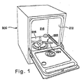
- Figure 1 is a perspective view of a dishwasher in accordance with the present invention.
- Figure 2 is a schematic illustration of the lower area of the dishwasher shown in FIG. 1, including the sump and the wash pump of the present invention.
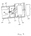
- Figure 3 is a sectional view of the pump and pump inlet area, illustrating the particle chopping system of the present invention and the coupling of the chopping system to the pump.
- Figure 4 is an exploded, perspective view of a second, more detailed embodiment of the particle chopping assembly of the present invention.
- Figure 5 is a sectional view of the second embodiment of the present invention, showing the particle chopping assembly assembled into the sump and coupled to the pump.
- Figure 6 is an exploded, perspective view of the second embodiment of the present invention, showing how the chopping assembly is assembled and secured into the inlet area of the sump.
- In accordance with the invention as shown in the drawings, and particularly as shown in FIGS. 1 and 2, an automatic dishwasher generally designated 200 includes an
interior tub 212 forming an interior wash chamber or dishwashingspace 214. Thewash tub 212 includes abottom wall 216 having a downwardly sloped portion which defines a lower tub region or sump 218 for receiving wash liquid inlet into thetub 212 through afill valve 220. A soil or particle separator andpump assembly 222 is located in the sump 218 for recirculating wash liquid from the sump 218 through thetub 212. Awash arm assembly 224 is provided above thepump assembly 222 and receives wash liquid from thepump system 222. - The particle separator/
pump assembly 222 includes apump 228. Thepump 228 is a centrifugal pump having awash impeller 230 rotated about a horizontal axis within apump chamber 232 which defines a spiral casing. During a wash cycle, thewash impeller 230, driven bymotor 234, draws wash liquid from the sump 218 through apump inlet area 236 including an inlet opening 237 and pumps the wash liquid out through amain outlet 238 and asecondary outlet 240. Wash liquid pumped through themain pump outlet 238 is directed to flow into thelower spray arm 224. Wash liquid flowing through the secondary outlet is directed to flow into a particle collector 242. Wash liquid is repeatedly recirculated throughout thewash tub 212 for removing particles from dishware supported therein. - It can be understood that at least a portion of the sump 218 may be formed by a
bottom member 244 which forms part of thetub bottom 216 defining the sump 218. Thebottom member 250 may also be used to help define thepump chamber 232, thepump inlet area 236, themain outlet 238 and thesecondary outlet 240. While this structure is shown as a particular embodiment of the invention, it is clearly just one example of how the present invention may be practiced. The sump, tub bottom, pump chamber and pump inlet area may be formed in any of a plurality of known ways such as shown in U.S. Pat No. 3,434,671 and 5,628,334, described above. - According to the present invention, wash liquid drawn into through the
pump inlet area 236 passes through aparticle chopping assembly 250, as shown in FIG. 3. The chopping orchopper assembly 250 includes a sizing plate orscreen 252 and a chopping orchopper blade 254. Thechopper blade 254 rotates adjacent thesizing plate 252 and chops food particles entrained within the wash liquid to size sufficient to allow the food particles to pass through thesizing plate 252. After being chopped and sized by thechopper assembly 250, the particles are drawn, along with the wash liquid, into thepump chamber 232. - The
chopping assembly 250 is uniquely designed to be a separate subassembly from theimpeller 230 such that thechopping assembly 250 may be located in theinlet area 236 independently of thewash impeller 230 andmotor 234. This is accomplished by having thechopping blade 254 rotatably supported on thescreen 252. In particular, thechopping blade 254 is mounted to adrive shaft 258 having a keyedfirst end 258a and a second end 258b. Thedrive shaft 258 is rotatably secured to thescreen 252. In this way, by forming anindependent chopping assembly 250, the distance between theblade 254 and thescreen 252 can be closely controlled ensuring that theblade 254 is relatively close to thescreen 252. - It should be recognized by one skilled in the art that although the
chopping assembly 250 of this embodiment and the below described second embodiment are shown located in an inlet area, the exact location of the chopping assembly is not critical and is not understood to be a limitation of the invention. Any location upstream from the wash impeller through which wash liquid flows can accommodate the chopping assembly of the present invention. - The
screen 254 may be mounted within theinlet area 236 by, for example, trapping thescreen 254 between aninlet shroud 256 which defines theinlet area 236, and a bottom wall formed by thebottom member 224. Alternatively, thescreen 252 could be secured within theinlet area 236 in any known manner such as through the use of clips, threaded fasteners or using other known methods. Once thescreen 252 is secured into theinlet area 236, the second end 258b of thedrive shaft 258 extends toward theimpeller 230. - The second end 258b is designed to detachably couple with a
drive extension 260 extending from theimpeller 230. The coupling arrangement between the second end of the drive shaft 258b and thedrive extension 260 is designed to accommodate the tolerance T in the end location of thedrive extension 260. In this way, by using a coupling system capable of accommodating tolerance T, thechopping blade assembly 250 can be rotatably driven and the distance between theblade 254 and thescreen 252 is not affected by the tolerance T. The detachable coupling system between thedrive shaft 258 and thedrive extension 260 may be any type of known coupling arrangement including using engaging teeth, using a shaft and spline arrangement insertable within a bore provided with a slot, or through other known coupling systems. - It can readily be appreciated that the chopping
assembly 250 can connect directly to theimpeller 230 through adrive extension 260 which is integrally formed as part of theimpeller 230. Alternatively, the drive extension could be a separate element connected theimpeller 230. Moreover, the motor drive shaft may be allowed to pass through theimpeller 230 such that the chopping assembly detachably couples directly to the motor drive shaft. In each case, the choppingassembly 250 detachably couples to a rotating element. - Turning now to FIGS. 4-6, a second, more detailed embodiment of the present invention can be explained. In FIG. 4 there is shown a chopper or chopping
assembly 300 which includes ascreen 302, achopping blade 304 and adrive shaft 308. Thescreen 302 includes acenter opening 328 and abearing 330 is provided about thecenter opening 328. Thebearing 330 may be insert molded onto thescreen 302 and may formed using a bearing material such as Rulon® made by Furon®. Thebearing 330 includes a first bearing surface 330a and asecond bearing surface 330b (FIG. 5). Thedrive shaft 308 has a first end which includes acylindrical portion 310 which terminates in ashoulder 312. A middle section of thedrive shaft 308 includes at least one flat 314. At asecond end 316, opposite the first end, a coupling element is provided including a plurality ofengagement teeth 318 and a centering hole 320 (see FIG. 5). - In assembling the
chopper assembly 300, aspring 322 is fit over thedrive shaft 308 to seat on a second shoulder 324. Awasher 326 is then inserted onto thedrive shaft 308 and thedrive shaft 308 is inserted through the center opening 328 in thescreen 302. Thechopping blade 304 is then inserted onto thedrive shaft 308 such that flat 332 engages the flat 314 formed onto the drive shaft. Apush nut fastener 334 is pressed onto thecylindrical end 310 of thedrive shaft 308 and seats the center portion of thechopping blade 304 against the first bearing surface 330a andwasher 326 againstsecond bearing surface 330b. Thefastener 334 secures the choppingassembly 300 together. While a push fastener is shown, any type of known and suitable fastener could be used. - After assembly, the chopping
assembly 300 may be secured within aninlet area 340 of the dishwasher pump. The chopping assembly may be secured in the inlet area by capturing the choppingassembly 300 between aninlet shroud 342 and abottom wall 344. As best seen in FIG. 6, the choppingassembly 300 may be initially located or secured into a groove or slot 346 provided in thebottom wall 344 and then theinlet shroud 342 may be attached to abottom wall 344 through the use of a threaded fastener 348. Theinlet shroud 342 may include a corresponding groove for engaging thescreen 302 such that the chopping assembly is securely located. Alternatively, the choppingassembly 300 may be secured within theinlet area 340 in an known manner such as through the use of clips, threaded fasteners or using other known methods. - When positioned within the
inlet area 340, thesecond end 316 of the drive shaft extends toward a rotating element orimpeller 350 which is located within apump chamber 352. The impeller operates to draw liquid through theinlet area 340 and into thepump chamber 352 whereupon liquid is pumped through a pump outlet (not shown). Theimpeller 350 includes adrive extension 354. Thedrive extension 354 includes a plurality of teeth orarms 356 and acenter pin 358. - When the
impeller 350 and the choppingassembly 300 are assembled into a dishwasher, thesecond end 316 and thedrive extension 354 are detachably coupled. In particular, thecenter pin 358 is received into the centeringhole 320 and theteeth 318 engage with theteeth 356 of thedrive extension 354. Theteeth hole 320 and thecenter pin 358 are purposefully designed to overlap a sufficient distance such that the coupling arrangement is capable of accommodating axial tolerance - tolerance along the axis of rotation - with regard to the relative position of thedrive extension 354. - It can be understood therefore, by one skilled in the art, that the axial position of the
chopping blade 304 and thescreen 302 relative to each other can be controlled independently of the position of therotating element 350. Looking at FIG. 5, it can be seen that as thedrive shaft 308 is rotated, the center portion of theblade 304 slides along the first bearing surface 330a. Thebearing 330, therefore, controls the spacing between theblade 304 and thescreen 302. Since the bearing can be formed with a relatively great degree of accuracy, the spacing between theblade 304 and thescreen 302 can be closely controlled. For example, the clearance between theblade 304 and thescreen 302 may be as little as 1.5 mm. This relatively small blade clearance promotes improved particle chopping or size reduction. - In addition to accommodating axial tolerance, the
chopper assembly 300 is configured to accommodate radial tolerance with regard to the position of therotating element 350 and driveextension 354. In particular, the center opening 328 of thebearing 330 is designed with a sufficient size to provide radial clearance for accommodating off center tolerance which may occur in the position of thedrive extension 354 and the center of thecenter opening 328. Off center may be caused by tolerance in positioning thescreen 302 and in positioning thedrive extension 354 of theimpeller 350. Thechopper assembly 300 permits thedrive shaft 308 to be axially positioned by thedrive extension 354 and rotated in a off-center position with regard to thecenter opening 328. - An additional aspect of the invention is provided by the configuration of the
chopping blade 304. Thechopping blade 304 is driven by themotor 234 in direction R during the recirculating periods and is designed to chop or reduce the size of food particles as it rotates adjacent thescreen 302. To that end, thechopping blade 304 includes a cutting surface 304a. One problem, however, that can occur when using a chopping assembly is that particles can pass by thechopping blade 304 and get stuck in thescreen 302. Alternatively, some stringy type particles can fail to be properly reduced in sized and pass through thescreen 302. To address this problem, thechopping blade 304 of the present invention includes one or more reverse angle surfaces or vanes 304b. These reverse angle surfaces 304b are configured to pump or lift liquid away from thescreen 302 when theblade 304 is driven in direction R. The reverse angle surfaces 304 are actually pumping against the flow of wash liquid through theinlet area 340. In this manner, particles which collect on thesizing screen 302 are lifted off the screen for additional chopping by the rotating chopping blade 30. - The chopping efficiency of the present invention is therefore promoted by having the
blade 304 close to thescreen 302 and by having theblade 304 lift soils away from the screen as the blade rotates such that soils can be reduced in size. As can be understood by one skilled in the art, the improved chopping efficiency of the particle chopping assembly allows for a more efficient dishwasher that uses less water. In particular, relatively small screen holes can be used allowing for the use of relatively small spray nozzles on thewash arm 224. Smaller nozzle holes in the wash arm allow for the use of less water by the dishwasher. - A method of assembling a dishwasher, which method does not form part of the invention is described below. In particular, the method includes assembling the chopping
assembly 300 including theparticle screen 302, thedrive shaft 308 and thechopping blade 304 wherein the drive shaft driving supports the chopping blade and is rotatably secured to the particle screen. As discussed above, this subassembly provides for the appropriate spacing between theblade 304 and thescreen 302. The choppingassembly 300 can then be secured within the sump of the dishwasher. A pump assembly includes a motor and theimpeller 350 may then be connected to the sump, wherein a drive extension of the impeller is drivingly coupled to the chopping assembly. Alternatively, the pump assembly may be connected to the sump and then the chopping assembly may be inserted into the sump. - The present invention, therefore, provides for a unique chopper assembly which forms a subassembly independent of the rotating or driving element. The unique chopper assembly is provided with a coupling arrangement which is capable of driving engagement with a rotating element and can accommodate axial tolerance of rotating element. The present invention further allows for unique manner of assembly a dishwasher and in particular the pump system of a dishwasher wherein the chopper assembly may be assembled into a dishwasher independently of the impeller/motor assembly.
- The present disclosure describes preferred embodiments of the invention, however, the invention is not limited to these embodiments. Variations may be made from the described preferred embodiments which are contemplated to be within the invention as set forth in the appended claims.
Claims (11)
- A dishwasher, comprising:a sump;a recirculating pump housing forming a pumping chamber, for recirculating wash liquid (232) having an inlet in fluid communication with the sump (218) and an outlet,a motor drive shaft (260) extending into the pumping chamber;an impeller (230, 350) connected to the motor drive shaft for rotation within the pumping chamber;a particle screen (252, 302); anda chopping blade (254, 304) rotatably supported on the particle screen and detachably coupled to the impeller for co-rotation therewith, characterised in that the particle screen (252, 302) is supported upstream of the impeller.
- The dishwasher according to claim 1, further comprising:a drive shaft (258, 308) rotatably supported on the particle screen (252, 302) and drivingly supporting the chopping blade (254, 304), the drive shaft having a coupling end (258b, 316) which detachable couples to the impeller.
- The dishwasher according to claim 2, wherein the coupling between the chopping blade (254, 304) and the impeller (230, 350) is capable of accommodating axial tolerance (T) between the coupling end of the drive shaft and the impeller.
- The dishwasher according to claim 2, wherein the impeller includes a drive extension (260, 354) which detachable couples to the coupling end (258b, 316) of the drive shaft.
- The dishwasher according to claim 4, wherein
the coupling end (316) includes a plurality of teeth (318) and the drive extension (354) includes a plurality of teeth (356);
the teeth (318) of the coupling end and the teeth (356) of the drive extension (354) engaging each other to drivingly couple the drive shaft (398) to the impeller (350), and
the teeth (318) of the coupling end and the teeth (356) of the drive extension over lap each other to accommodate axial tolerance (T) in the axial position of the impeller. - The dishwasher according to claim 1, further comprising:the particle screen (302) having a center opening (328) provided with a bearing (330) having a first bearing surface (330a) and an opposite second bearing surface (330b), anda drive shaft (398) rotatably supported on the particle screen (302), the drive shaft having a first end extending through the center opening of the particle screen wherein the chopping blade (399) is mounted to the first end of the drive shaft and is biased against the first bearing surface (330a), the drive shaft further having a coupling end (316) which detachably couples to the impeller.
- The dishwasher according to claim 1, further comprising:the particle screen (302) having a center opening (328) provided with a bearing (330) having a first bearing surface (330a) and an opposite second bearing surface (330b),a drive shaft (398) having a first end (310) extending through the center opening of the particle screen, the drive shaft further having a coupling end (316) including a shoulder (324), the coupling end detachably couples to the impeller (350),a fastener (334) for securing the chopping blade (394) onto the first end (310) of the drive shaft (398) such that the chopping blade is drivingly supported on the drive shaft and seats on the first bearing surface (330a);a washer (326) disposed about the drive shaft (398) adjacent the second bearing surface (330b); anda spring (322) disposed about the drive shaft (308) and captured between the shoulder (324) and the washer (326) such that chopping blade (304) is biased toward the particle screen (302).
- The dishwasher according to claim 1, wherein the chopping blade (304) further comprises:a reverse angle (304b) portion which directs wash liquid upstream, away from the particle screen (302) when the chopping blade (304) is rotated along with the impeller (350).
- The dishwasher according to claim 4, wherein
the coupling end (316) includes a plurality of teeth (318) and a centering hole (320) and the drive extension (354) includes a plurality of teeth (356) and a center pin (358),
the centering hole (320) receiving the center pin (358) and the teeth of the coupling end and the teeth of the drive extension engaging each other to drivingly couple the drive shaft to the rotating element, and
the teeth (318) of the coupling end and the teeth (356) of the drive extension over lap each other to accommodate axial tolerance (T) of the axial position of the impeller. - The dishwasher according to claim 1, further comprising:a drive shaft (258, 398) rotatably supported on the particle screen (252, 302) and drivingly supporting the chopping blade (254, 304) within 2mm or less of the particle screen (252, 302), the drive shaft having a coupling end (258b, 316) which detachable couples to the impeller (230, 350).
- The dishwasher according to claim 10, wherein the coupling between the chopping blade (254, 304) and the impeller is capable of accommodating axial tolerance (T) between the coupling end of the drive shaft and the impeller.
Applications Claiming Priority (4)
| Application Number | Priority Date | Filing Date | Title |
|---|---|---|---|
| US326303 | 1994-10-19 | ||
| US09/326,303 US6418943B1 (en) | 1999-06-04 | 1999-06-04 | Wash liquid circulation system for a dishwasher |
| US542751 | 2000-04-04 | ||
| US09/542,751 US6454872B1 (en) | 1999-06-04 | 2000-04-04 | Dishwasher with food particle chopping assembly |
Publications (3)
| Publication Number | Publication Date |
|---|---|
| EP1057445A2 EP1057445A2 (en) | 2000-12-06 |
| EP1057445A3 EP1057445A3 (en) | 2002-04-17 |
| EP1057445B1 true EP1057445B1 (en) | 2006-02-15 |
Family
ID=26985343
Family Applications (1)
| Application Number | Title | Priority Date | Filing Date |
|---|---|---|---|
| EP00111743A Expired - Lifetime EP1057445B1 (en) | 1999-06-04 | 2000-06-02 | Dishwasher with food particle chopping assembly |
Country Status (3)
| Country | Link |
|---|---|
| US (1) | US6454872B1 (en) |
| EP (1) | EP1057445B1 (en) |
| DE (1) | DE60025974T2 (en) |
Families Citing this family (25)
| Publication number | Priority date | Publication date | Assignee | Title |
|---|---|---|---|---|
| US6782899B2 (en) * | 2000-12-14 | 2004-08-31 | Lg Electronics Inc. | Dishwasher |
| KR100457596B1 (en) * | 2003-01-06 | 2004-11-17 | 엘지전자 주식회사 | Filter assembly of dish washer |
| US6887318B2 (en) * | 2003-07-09 | 2005-05-03 | Whirlpool Corporation | Adaptive fill for dishwashers |
| DE10346675A1 (en) * | 2003-10-08 | 2005-05-04 | Bsh Bosch Siemens Hausgeraete | Dishwasher with comminution device |
| WO2005105311A1 (en) | 2004-04-26 | 2005-11-10 | Emerson Electric Co. | Food waste disposer shredder assembly |
| SE527020C2 (en) * | 2004-04-27 | 2005-12-06 | Getinge Disinfection Ab | Disinfection equipment with pump device |
| US7497222B2 (en) * | 2004-07-02 | 2009-03-03 | Bsh Bosch Und Siemens Hausgeraete | Comminution device and method for comminuting residue in a dishwasher |
| US7472714B2 (en) * | 2005-02-09 | 2009-01-06 | Maytag Corporation | Dishwasher drain pump assembly |
| US8066821B2 (en) * | 2005-02-09 | 2011-11-29 | Whirlpool Corporation | System for limiting pressure in a fine filter chamber for a dishwasher |
| US20060237035A1 (en) * | 2005-04-25 | 2006-10-26 | Viking Range Corporation | Dishwasher with food particle disposal system |
| US8033486B2 (en) * | 2005-12-16 | 2011-10-11 | Emerson Electric Co. | Waste line connector assembly |
| US7670439B2 (en) * | 2006-03-31 | 2010-03-02 | Maytag Corporation | Chopping system for a dishwasher pump assembly |
| SE531139C2 (en) * | 2007-05-08 | 2009-01-07 | Itt Mfg Enterprises Inc | Pump unit and method |
| KR101669282B1 (en) * | 2010-03-31 | 2016-10-25 | 엘지전자 주식회사 | A dishwasher |
| CN201810546U (en) * | 2010-09-14 | 2011-04-27 | 德昌电机(深圳)有限公司 | Tight coupling structure between motor shaft and pump |
| US8888931B2 (en) | 2010-12-14 | 2014-11-18 | General Electric Company | Dishwasher pump inlet macerator system |
| US9872598B2 (en) | 2011-07-06 | 2018-01-23 | Viking Range, Llc | Drying system for a dishwasher |
| US10136791B2 (en) | 2011-10-17 | 2018-11-27 | Whirlpool Corporation | Convertible dishwasher |
| US9655495B2 (en) | 2012-12-06 | 2017-05-23 | Whirlpool Corporation | Dishwasher including an inclined grate for filtration |
| US10130239B2 (en) * | 2016-07-22 | 2018-11-20 | Haier Us Appliance Solutions, Inc. | Filter assembly for a dishwasher appliance |
| US10813527B2 (en) * | 2017-08-29 | 2020-10-27 | Whirlpool Corporation | Blade and pump impeller assembly for a dishwasher |
| CN108354565B (en) * | 2018-01-03 | 2024-04-05 | 祝孔成 | Multifunctional tableware cleaning and meal residue smashing composite device |
| CN109707663B (en) * | 2019-03-20 | 2024-09-27 | 周小波 | Impeller, water pump and cleaning machine |
| CN109875480A (en) * | 2019-04-02 | 2019-06-14 | 周小波 | A water pump and a dishwasher |
| CN117898651B (en) * | 2024-03-05 | 2025-01-28 | 浙江森歌智能厨电股份有限公司 | Dishwasher with residue processing device and control method thereof |
Family Cites Families (25)
| Publication number | Priority date | Publication date | Assignee | Title |
|---|---|---|---|---|
| GB814417A (en) * | 1956-10-15 | 1959-06-03 | Thomas Cropper Ryley Shepherd | Improvements in or relating to controlling the flow of liquids in dish washing machines |
| US2286520A (en) * | 1941-04-28 | 1942-06-16 | Dale O Tranbarger | Garbage disposer |
| US2421064A (en) * | 1944-10-09 | 1947-05-27 | Frank T Hilliker | Garbage disposal device |
| US2729219A (en) * | 1952-02-19 | 1956-01-03 | Gen Motors Corp | Dishwashing machine |
| US3025864A (en) * | 1957-08-16 | 1962-03-20 | Gertrude W Ensign | Dishwasher |
| US3129711A (en) * | 1960-09-29 | 1964-04-21 | Gorman Rupp Ind Inc | Dishwasher recirculating assembly |
| US3356097A (en) * | 1965-05-21 | 1967-12-05 | Schaap Theodore | Combination disposal and washer |
| US3370598A (en) * | 1965-10-20 | 1968-02-27 | Whirlpool Co | Dishwasher |
| US3434671A (en) | 1966-01-13 | 1969-03-25 | Gen Electric | Pump for dishwasher |
| US3591095A (en) * | 1968-11-25 | 1971-07-06 | Albert Di Stefano | Combination garbage grinder and pump |
| US3653807A (en) * | 1970-08-24 | 1972-04-04 | Whirlpool Co | Method and means for shredding and filtering lint in a washing machine |
| US3981456A (en) | 1975-10-31 | 1976-09-21 | General Electric Company | Food particle macerating means |
| US4201345A (en) | 1978-08-04 | 1980-05-06 | General Electric Company | Food cutter for dishwasher |
| US4228962A (en) * | 1979-06-14 | 1980-10-21 | Whirlpool Corporation | Comminuting liquid swirler |
| US4350306A (en) | 1980-09-22 | 1982-09-21 | Whirlpool Corporation | Chopper for dishwasher soil separator |
| US4448359A (en) | 1982-06-10 | 1984-05-15 | Hobart Corporation | Combination drain pump and grinding apparatus |
| US4822241A (en) * | 1987-08-03 | 1989-04-18 | Whirlpool Corporation | Automatic dishwasher with a pump having a selectively adjustable impeller clearance |
| US4795102A (en) | 1987-12-04 | 1989-01-03 | Maytag Corporation | Dishwasher pump with particle cutter |
| SE500246C2 (en) * | 1990-04-26 | 1994-05-24 | Electrolux Ab | Arrangement by a dishwasher |
| US5377707A (en) * | 1993-11-01 | 1995-01-03 | White Consolidated Industries, Inc. | Dishwasher pump and filtration system |
| US5628334A (en) | 1995-04-25 | 1997-05-13 | White Consolidated Industries, Inc. | Dishwasher with food particle macerator and mincer |
| US5700329A (en) * | 1996-05-22 | 1997-12-23 | White Consolidated Industries, Inc. | Filter standpipe for dishwasher |
| JPH1033448A (en) * | 1996-07-26 | 1998-02-10 | Sanyo Electric Co Ltd | Dishwasher and two step washing |
| US5909743A (en) * | 1997-09-10 | 1999-06-08 | Whirlpool Corporation | Automatic purge filtration system for a dishwasher |
| US5762080A (en) * | 1997-01-24 | 1998-06-09 | White Consolidated Industries, Inc. | Dishwasher cycle pulsing pump out of collection chamber |
-
2000
- 2000-04-04 US US09/542,751 patent/US6454872B1/en not_active Expired - Lifetime
- 2000-06-02 EP EP00111743A patent/EP1057445B1/en not_active Expired - Lifetime
- 2000-06-02 DE DE60025974T patent/DE60025974T2/en not_active Expired - Lifetime
Also Published As
| Publication number | Publication date |
|---|---|
| US6454872B1 (en) | 2002-09-24 |
| EP1057445A2 (en) | 2000-12-06 |
| DE60025974T2 (en) | 2006-08-17 |
| EP1057445A3 (en) | 2002-04-17 |
| DE60025974D1 (en) | 2006-04-20 |
Similar Documents
| Publication | Publication Date | Title |
|---|---|---|
| US6454872B1 (en) | Dishwasher with food particle chopping assembly | |
| US4448359A (en) | Combination drain pump and grinding apparatus | |
| US5377707A (en) | Dishwasher pump and filtration system | |
| US6418943B1 (en) | Wash liquid circulation system for a dishwasher | |
| EP1432533B1 (en) | Improved pot and pan washing machine | |
| US5967747A (en) | Low noise fan | |
| CA1159751A (en) | Vertical soil separator for dishwasher | |
| US5909743A (en) | Automatic purge filtration system for a dishwasher | |
| US7497222B2 (en) | Comminution device and method for comminuting residue in a dishwasher | |
| US5848601A (en) | Dishwasher pump having soil collection system | |
| EP0528571A1 (en) | Soil separator for a domestic dishwasher | |
| AU2002335694A1 (en) | Improved pot and pan washing machine | |
| CA1159749A (en) | Chopper for dishwasher soil separator | |
| US9307885B2 (en) | Rotating filter assembly for a dishwasher | |
| US20200054187A1 (en) | Pot and pan washing machine | |
| CA1290980C (en) | Dishwasher pump with particle cutter | |
| EP0744151A2 (en) | Dishwasher with balancing vanes on pump impeller | |
| CA1159750A (en) | Soil separator drain valve | |
| US20060174925A1 (en) | Dishwasher drain pump assembly | |
| US6969018B2 (en) | Sanitary shredder | |
| EP0842632A2 (en) | Automatic purge filtration system for a dishwasher | |
| EP0079752B1 (en) | A dishwasher incorporating combination drain pump and grinding apparatus | |
| KR900000592Y1 (en) | Pulverizer of residue of food in a dinner washer |
Legal Events
| Date | Code | Title | Description |
|---|---|---|---|
| PUAI | Public reference made under article 153(3) epc to a published international application that has entered the european phase |
Free format text: ORIGINAL CODE: 0009012 |
|
| AK | Designated contracting states |
Kind code of ref document: A2 Designated state(s): DE FR GB IT Kind code of ref document: A2 Designated state(s): AT BE CH CY DE DK ES FI FR GB GR IE IT LI LU MC NL PT SE |
|
| AX | Request for extension of the european patent |
Free format text: AL;LT;LV;MK;RO;SI |
|
| PUAL | Search report despatched |
Free format text: ORIGINAL CODE: 0009013 |
|
| AK | Designated contracting states |
Kind code of ref document: A3 Designated state(s): AT BE CH CY DE DK ES FI FR GB GR IE IT LI LU MC NL PT SE |
|
| AX | Request for extension of the european patent |
Free format text: AL;LT;LV;MK;RO;SI |
|
| 17P | Request for examination filed |
Effective date: 20020920 |
|
| AKX | Designation fees paid |
Free format text: DE FR GB IT |
|
| 17Q | First examination report despatched |
Effective date: 20050214 |
|
| GRAP | Despatch of communication of intention to grant a patent |
Free format text: ORIGINAL CODE: EPIDOSNIGR1 |
|
| GRAS | Grant fee paid |
Free format text: ORIGINAL CODE: EPIDOSNIGR3 |
|
| GRAA | (expected) grant |
Free format text: ORIGINAL CODE: 0009210 |
|
| AK | Designated contracting states |
Kind code of ref document: B1 Designated state(s): DE FR GB IT |
|
| REG | Reference to a national code |
Ref country code: GB Ref legal event code: FG4D |
|
| REF | Corresponds to: |
Ref document number: 60025974 Country of ref document: DE Date of ref document: 20060420 Kind code of ref document: P |
|
| ET | Fr: translation filed | ||
| PLBE | No opposition filed within time limit |
Free format text: ORIGINAL CODE: 0009261 |
|
| STAA | Information on the status of an ep patent application or granted ep patent |
Free format text: STATUS: NO OPPOSITION FILED WITHIN TIME LIMIT |
|
| 26N | No opposition filed |
Effective date: 20061116 |
|
| REG | Reference to a national code |
Ref country code: FR Ref legal event code: PLFP Year of fee payment: 17 |
|
| PGFP | Annual fee paid to national office [announced via postgrant information from national office to epo] |
Ref country code: DE Payment date: 20160524 Year of fee payment: 17 Ref country code: GB Payment date: 20160601 Year of fee payment: 17 |
|
| PGFP | Annual fee paid to national office [announced via postgrant information from national office to epo] |
Ref country code: FR Payment date: 20160516 Year of fee payment: 17 |
|
| PGFP | Annual fee paid to national office [announced via postgrant information from national office to epo] |
Ref country code: IT Payment date: 20160621 Year of fee payment: 17 |
|
| REG | Reference to a national code |
Ref country code: DE Ref legal event code: R119 Ref document number: 60025974 Country of ref document: DE |
|
| GBPC | Gb: european patent ceased through non-payment of renewal fee |
Effective date: 20170602 |
|
| REG | Reference to a national code |
Ref country code: FR Ref legal event code: ST Effective date: 20180228 |
|
| PG25 | Lapsed in a contracting state [announced via postgrant information from national office to epo] |
Ref country code: GB Free format text: LAPSE BECAUSE OF NON-PAYMENT OF DUE FEES Effective date: 20170602 Ref country code: DE Free format text: LAPSE BECAUSE OF NON-PAYMENT OF DUE FEES Effective date: 20180103 |
|
| PG25 | Lapsed in a contracting state [announced via postgrant information from national office to epo] |
Ref country code: FR Free format text: LAPSE BECAUSE OF NON-PAYMENT OF DUE FEES Effective date: 20170630 Ref country code: IT Free format text: LAPSE BECAUSE OF NON-PAYMENT OF DUE FEES Effective date: 20170602 |