EP1056260A2 - Radio communication device - Google Patents
Radio communication device Download PDFInfo
- Publication number
- EP1056260A2 EP1056260A2 EP00304422A EP00304422A EP1056260A2 EP 1056260 A2 EP1056260 A2 EP 1056260A2 EP 00304422 A EP00304422 A EP 00304422A EP 00304422 A EP00304422 A EP 00304422A EP 1056260 A2 EP1056260 A2 EP 1056260A2
- Authority
- EP
- European Patent Office
- Prior art keywords
- ring
- communication device
- display
- phone
- movement
- Prior art date
- Legal status (The legal status is an assumption and is not a legal conclusion. Google has not performed a legal analysis and makes no representation as to the accuracy of the status listed.)
- Withdrawn
Links
Images



Classifications
-
- G—PHYSICS
- G04—HOROLOGY
- G04C—ELECTROMECHANICAL CLOCKS OR WATCHES
- G04C3/00—Electromechanical clocks or watches independent of other time-pieces and in which the movement is maintained by electric means
- G04C3/001—Electromechanical switches for setting or display
-
- G—PHYSICS
- G04—HOROLOGY
- G04G—ELECTRONIC TIME-PIECES
- G04G21/00—Input or output devices integrated in time-pieces
- G04G21/04—Input or output devices integrated in time-pieces using radio waves
-
- G—PHYSICS
- G04—HOROLOGY
- G04R—RADIO-CONTROLLED TIME-PIECES
- G04R60/00—Constructional details
-
- H—ELECTRICITY
- H04—ELECTRIC COMMUNICATION TECHNIQUE
- H04B—TRANSMISSION
- H04B1/00—Details of transmission systems, not covered by a single one of groups H04B3/00 - H04B13/00; Details of transmission systems not characterised by the medium used for transmission
- H04B1/38—Transceivers, i.e. devices in which transmitter and receiver form a structural unit and in which at least one part is used for functions of transmitting and receiving
- H04B1/3827—Portable transceivers
- H04B1/385—Transceivers carried on the body, e.g. in helmets
-
- H—ELECTRICITY
- H04—ELECTRIC COMMUNICATION TECHNIQUE
- H04M—TELEPHONIC COMMUNICATION
- H04M1/00—Substation equipment, e.g. for use by subscribers
- H04M1/26—Devices for calling a subscriber
- H04M1/27—Devices whereby a plurality of signals may be stored simultaneously
- H04M1/274—Devices whereby a plurality of signals may be stored simultaneously with provision for storing more than one subscriber number at a time, e.g. using toothed disc
- H04M1/2745—Devices whereby a plurality of signals may be stored simultaneously with provision for storing more than one subscriber number at a time, e.g. using toothed disc using static electronic memories, e.g. chips
- H04M1/275—Devices whereby a plurality of signals may be stored simultaneously with provision for storing more than one subscriber number at a time, e.g. using toothed disc using static electronic memories, e.g. chips implemented by means of portable electronic directories
-
- H—ELECTRICITY
- H04—ELECTRIC COMMUNICATION TECHNIQUE
- H04M—TELEPHONIC COMMUNICATION
- H04M1/00—Substation equipment, e.g. for use by subscribers
- H04M1/72—Mobile telephones; Cordless telephones, i.e. devices for establishing wireless links to base stations without route selection
- H04M1/724—User interfaces specially adapted for cordless or mobile telephones
-
- H—ELECTRICITY
- H04—ELECTRIC COMMUNICATION TECHNIQUE
- H04M—TELEPHONIC COMMUNICATION
- H04M1/00—Substation equipment, e.g. for use by subscribers
- H04M1/72—Mobile telephones; Cordless telephones, i.e. devices for establishing wireless links to base stations without route selection
- H04M1/724—User interfaces specially adapted for cordless or mobile telephones
- H04M1/72403—User interfaces specially adapted for cordless or mobile telephones with means for local support of applications that increase the functionality
- H04M1/72409—User interfaces specially adapted for cordless or mobile telephones with means for local support of applications that increase the functionality by interfacing with external accessories
- H04M1/72412—User interfaces specially adapted for cordless or mobile telephones with means for local support of applications that increase the functionality by interfacing with external accessories using two-way short-range wireless interfaces
-
- H—ELECTRICITY
- H04—ELECTRIC COMMUNICATION TECHNIQUE
- H04M—TELEPHONIC COMMUNICATION
- H04M1/00—Substation equipment, e.g. for use by subscribers
- H04M1/60—Substation equipment, e.g. for use by subscribers including speech amplifiers
- H04M1/6033—Substation equipment, e.g. for use by subscribers including speech amplifiers for providing handsfree use or a loudspeaker mode in telephone sets
- H04M1/6041—Portable telephones adapted for handsfree use
-
- H—ELECTRICITY
- H04—ELECTRIC COMMUNICATION TECHNIQUE
- H04M—TELEPHONIC COMMUNICATION
- H04M1/00—Substation equipment, e.g. for use by subscribers
- H04M1/72—Mobile telephones; Cordless telephones, i.e. devices for establishing wireless links to base stations without route selection
- H04M1/724—User interfaces specially adapted for cordless or mobile telephones
- H04M1/72403—User interfaces specially adapted for cordless or mobile telephones with means for local support of applications that increase the functionality
- H04M1/7243—User interfaces specially adapted for cordless or mobile telephones with means for local support of applications that increase the functionality with interactive means for internal management of messages
-
- H—ELECTRICITY
- H04—ELECTRIC COMMUNICATION TECHNIQUE
- H04M—TELEPHONIC COMMUNICATION
- H04M2250/00—Details of telephonic subscriber devices
- H04M2250/02—Details of telephonic subscriber devices including a Bluetooth® interface
Definitions
- the present invention is generally related to a communication device, especially to a communication device which has small dimensions and may be sized for attachment to a wrist.
- Today communication devices e.g. mobile phones working in cellular networks for enabling phone calls comprise a numerical keypad with twelve keys to enter phone numbers and characters and some special keys for controlling the phone functions. For operating the keys the user can hold the communication device comfortably in one hand and operates the key with his fingers.
- a display which is usually placed above the keypad on the front side of the communication device displays information, which is related to the input by the user or to the state of the communication device. For example if the user enters a phone number by using the numerical keypad the number is displayed on the display. Furthermore the user can scroll through a stored phonebook by using the up and down keys and he can select one of the names, which are shown on the display. On activation of a call key a phone call to the selected person is established by using the telephone number which is associated to this name in the memory of the device.
- This kind of user interface is for example used by the Nokia 3110 mobile phone which is designed for use in the cellular telephone system GSM (Global System for Mobile Communications).
- a first part comprises at least a power supply, a radio part (transceiver) to communicate within the radio telephone system, e.g. with a base station or another radio phone, an antenna and data transfer means for communicating with the second part.
- the second part comprises at least keys and data transfer means for communicating with the first part.
- the second part can be carried on the wrist of the user like a wristwatch.
- the numerical keyboard as it is disclosed in EP 0602828 A1, comprises very small keys, which can be operated only with fingernails or by the usage of a special stick or the tip of a pen. Also if the phone has the dimensions of a pocket watch the dimensions of the keys of a numerical keypad are to small for comfortable operation.
- a radio communication device sized for attachment to a wrist, comprises transceiver means for transmitting and receiving radio signals comprising data, a display for displaying data, processor means including a memory for controlling the transceiver means and the display and user input means, connected to the processor means.
- the user input means comprise a substantially circular ring surrounding the display. The ring is mounted for rotational movement about an axis passing substantially through the centre of the ring and substantially perpendicular to the plane of the ring wherein the processor means is responsive to the movement of the means to control the transceiver and the display.
- the radio communication device is e.g. a mobile radiotelephone, a pager or a cordless telephone.
- the radio communication device may represent the user interface of a mobile radiotelephone.
- the user interface itself only contains a short range radio transceiver and communication to the cellular network is done through a kind of booster which is equipped with a short range radio interface for communication with the user interface and a cellular phone transceiver for communication with the cellular telephone network.
- the communication device may have the shape of a wristwatch or a pocket watch with a cylindrical shape.
- the circular ring of the communication device is mounted for translational displacement of the ring parallel to the plane of the ring. Shifting the ring in any direction can enter this way data, which is selected by rotation of the ring. Different shifting directions could lead to different actions.
- the ring may be shifted to four directions (left, right, up,down) to control four different actions.
- the ring may be shifted in any direction and only one operation is triggered this way.
- the circular ring of the communication device is mounted for translational displacement of the ring perpendicular to the plane of the ring. This way data, which is selected by the rotation of the ring, can be entered by pressing down the ring. Any other functions/actions can also be initiated by pressing down the ring.
- the communication device comprises means for detecting clockwise and anti-clockwise rotation of the ring.
- the detection of the rotation direction is for example important while the user is selecting characters from the alphabet. For example the user does not need to rotate the ring for a lot of steps in clockwise direction if he wants to choose the letter "A" when the actually selected letter is a "B". If the device detects the anti-clockwise rotation the user only needs to rotate the ring for one step anti-clockwise.
- This kind of data can represent a telephone number, which is entered by a user for establishing a phone call to a telephone.
- the data selected by the rotation of the ring can also be a name which is associated with a telephone number in the phone book memory of the communication device. While rotating the ring the user scrolls through the phonebook of the communication device and selects a name, and thereby the phone number by shifting or pressing the ring.
- This data could also be a e.g. short message, which is entered and/or edited by the user input means.
- the entered short message can be send to a recipient by the radio communication device then.
- the rotational movement of the input ring can advantageously be detected by electro-optical conversion means.
- the electro-optical conversion means can be, for example, an infra red light emitting diode (IR-LED) and an infrared detector.
- IR-LED infra red light emitting diode
- the ring contains at its underside light reflecting and non-light reflecting areas and while rotation of the ring the IR detector detects changes from the reflecting to non-reflecting area. These changes are indicated to the processing means.
- the translational displacement of the ring e.g. shifting the ring or pressing down the ring is advantageously indicated to the microprocessor by key buttons.
- Key buttons on the inner side of the ring indicates to the processing means that the ring is shifted and key buttons below the ring indicate to the processing means that the ring is pressed down.
- Fig. 1 discloses a radio communication device 1 in accordance to the invention.
- the device is built in the shape of a wristwatch and may contain the components of a wristwatch for displaying time of day.
- the following description does not refer to the watch functionality as long at is not related to the functions of the radio communication device 1.
- the radio communication device is referred to as a wrist watch phone 1 in the following.
- the wrist watch phone 1 according to the invention comprises a housing 7, a first and a second strap 5 with a closing mechanism 6 for attaching the wrist watch phone 1 to the wrist of a user.
- the wristwatch phone may further comprise a clock face 9 and two watch hands 10 for presenting the time of day.
- the wristwatch phone 1 further comprises an opening 3 for a microphone and openings for a loudspeaker 2.
- the microphone and loudspeaker itself are placed within the housing 7 below the respective openings.
- a display 4 is placed within the clock face.
- the display in Fig. 1 actually presents an incomplete telephone number, which is for example just entered by a user.
- the user operates the ring 8 which can be rotated in the directions a (clockwise) and b (anti-clockwise) as they are represented by the arrows on the ring 8.
- the arrows are only shown in this drawing to explain the functions.
- the ring 8 is mounted for rotational movement about an axis passing substantially through the centre of the ring and perpendicular to the plane of the ring.
- the entered telephone number may be selected by pressing down the input ring 8, by shifting the input ring or pressing any other selection key which is placed on the housing 7 of the wrist phone.
- the mechanism to detect when the ring is pressed down or shifted is explained with reference to the drawings Fig. 7, Fig. 12 and Fig. 13 later on.
- the wrist watch phone 1 basically includes a microprocessor (control unit) 40 which is connected to various input devices 41.
- One of the input devices according to the invention is the input ring 8.
- the microprocessor is further connected to a display 42.
- the microprocessor 40 is further connected to a microphone 47 and a loudspeaker 48 for enabling voice communication.
- a radio frequency transmitter 46 and a radio frequency receiver 45 together form a transceiver for transmitting and receiving radio signal, which comprise data. Such data can be voice signals or data messages.
- An antenna 16 is also part of the wristwatch phone.
- a battery 44 is included.
- the memory 43 mainly contains data, which is necessary for operating the telephone.
- the memory might also contain a phonebook, which is entered by the user of the phone.
- the phonebook contains telephone numbers and accompanying names. When the name and telephone numbers are entered into the phonebook the user can easily select the name of the person he desires to call by scrolling through the phonebook in the memory. Scrolling through the phonebook is advantageously done by rotating the input ring 8.
- the microprocessor 40 is connected to the input devices 41 and responsive to the input made by the input devices to control the receiver 46, the transmitter 45 and the display 42.
- the transmitter 45 and receiver 46 together with antenna 14 can be built in a way to connect the wrist watch phone through radio waves directly to a cellular phone network as it is for example known as GSM (Global System for Mobile communication).
- GSM Global System for Mobile communication
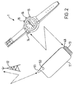
- the heat dissipation of the transmitter 45 might make it worthwhile to connect the wrist watch phone 1 through a short range radio link to a kind of booster 11 first, as it is shown in Fig. 2.
- the booster enables the cellular radio communication through antenna 51 with the cellular network, which is represented by base station 12.
- the booster 11 is equipped with a short-range radio interface 13 and transmits and receives data from and to the wristwatch phone through antenna 46.
- the booster 11 can be turned on and off by operating key button 50.
- the short-range radio interface can be for example a low power radio frequency link as it is for example developed by the so-called "Bluetooth" consortium.
- Transmitters according to the Bluetooth standard transmit with a much lower RF energy compared to cellular phone transceiver and this way heat dissipation of the transmitter 45 of the wrist watch phone 1 is drastically reduced.
- Fig. 2 furthermore a button 16, for setting the wrist watch time, and two control buttons 15 are presented at the wrist watch phone 1.
- the control buttons 15 can be used for controlling watch and phone functions, as it will be explained later on.
- Fig. 3 which can be understood in combination with Fig. 4, 5 and 9, shows a front view of the wrist watch phone 1.
- the input ring 8 is removed from the wristwatch phone 1.
- the rear-side of the input ring 8 of the wrist watch phone 1 is shown in Fig. 9.
- the input ring 8 has at its rear surface sections 18.
- the sections 18 reflect light, especially infrared (IR) light and the sections 17 are unable to reflect infrared light.
- the sections 17 can be for example painted black or the surface is scratched in order to disperse light.
- Below input ring 8, on the left lower corner of the wristwatch phone in Fig. 3, an infrared light emitting diode 19 and an IR light receiving diode 20 are placed below input ring 8, on the left lower corner of the wristwatch phone in Fig. 3, an infrared light emitting diode 19 and an IR light receiving diode 20 are placed.
- Fig. 4 shows the section view c-c of Fig.
- IR light transmitted by the diode 19 is not reflected while a not reflecting section 17 is above the IR diode 19 and the IR receiver 20.
- the IR diode 20 is coupled to the microprocessor 40.
- the microprocessor 40 recognises changes of the logical signals. If the user enters for example a telephone number as explained with reference to Fig. 1, the microprocessor changes a digit of the number, which is displayed, on display 4 in response to each level change. Without recognition of the rotation direction the microprocessor might only change the number to higher values. If the digit "4" is displayed but the digit "3" should be selected the user has to rotate the input ring 8 in any direction until the microprocessor has recognised nine signal level changes from IR receiver 20 and the digit "3" is displayed.
- FIG. 5 shows the section view b-b of Fig. 3.
- the input ring 8 is shown in its mounted position.
- a pin 21 is pressed by the force of the spring 22 against the rear surface of the input ring 8.
- the pin 21 projects substantially half out of the housing 7 and projects half into the housing.
- the pin 21 can furthermore cant over to the left and right side around the virtual axis 26.
- the spring 22 is mounted on a metal plate 14, which is connected to electrical ground. The metal plate can be shifted to the left and right side and responsive to the shifting direction the switch 25a or the switch 25b is closed.
- FIG. 6 An example when the ring is rotated anticlockwise is shown in Fig. 6.
- the arrow within input ring 8 in Fig. 6 represents the rotation direction.
- the upper tip of the pin 21 is pressed against the input ring and by the friction between the input ring 8 and the tip of pin 21, the tip of the pin is canted over to the right side.
- Due to the virtual axis 27 the lower part within the housing 7 is canted over to the left side now and this way the spring and thereby the metal plate 14 is shifted to the left side.
- the contact plates of switch 25b are connected to each other.
- the switch 25b is connected to the microprocessor 40 which now recognises that the input ring is rotated anti-clockwise.
- the microprocessor decreases the number on the display when also the IR detector senses a level change.
- Fig. 7 another advantageous embodiment of the wrist watch phone 1 is shown.
- the input ring 8 can be used as described before but additionally the input ring 8 can be translational displaced parallel to the plane of the ring.
- the translational displacement is sensed by key buttons 26a to 26d which are connected to the microprocessor 40.
- the entered digit of a telephone number can for example be selected by shifting the input ring to the left as presented by the arrows on the ring.
- key button 26c is operated and the microprocessor is informed that the last digit of the phone number is selected now. The next digit can be entered by rotating the ring 8 again.
- Shifting the ring 8 to the left can for example be the signal for the microprocessor 40 that the number, which was entered so far, should be corrected and jumps back to the previous digit in the phone number when switch 26a is closed.
- Shifting the ring 8 to the top i.e. closing key button 26d
- Shifting the ring 8 to the bottom i.e. closing key button 26b
- Shifting the ring 8 to the bottom can be the sign for the microprocessor to cancel the whole procedure.
- the key buttons 26a to 26d are located between the inner circle 8a of the input ring 8 and the bezel 28, which covers the clock face. They can also be hidden below the input ring 8, which is not shown here.
- the input ring 8 may be shifted in four direction (up, down, left, right) to control four different operations but it could also be possible to detect if two of the key buttons 26a to 26d are closed. If the ring 8 is for example shifted to the top and to the right the key buttons 26c and 26d are closed. This way eight different operations can be selected. Furthermore it may be possible to shift the ring in any direction and only one operation is performed when the ring is shifted in any direction.
- Fig. 8 shows the section view a-a of Fig. 13. This section view shows the input ring 8, which is mounted, between the housing 7 and the bezel 28.
- the input ring 8 is first laid on the phone 8 and then the bezel 28 is mounted on the housing 7 in a manner it is known to persons skilled in the art. If the input ring is mounted as shown in Fig. 8 no additional device is necessary to keep it in its position.
- Fig. 10 another alternative embodiment of the inventive concept is disclosed.
- the input ring 8 can be used as described in the foregoing description, i.e. it can be rotated clockwise and anti-clockwise for operating the wrist watch phone 1.
- the key buttons 15a and 15b are used as a tactile user interface for the wrist watch phone 1.
- the clock face 28 is completely occupied by electronic display, e.g. a full graphical LCD display.
- Full graphical LCD displays are known from mobile phones today.
- the Nokia mobile phone of the 6100 series might be taken as one example.
- Full graphical display means that each pixel of the display can be controlled by the microprocessor 40. It is possible to display any kind of information on any place of the display. In this example the time of day (15:45) is displayed on the left side of display 28 and a telephone number (01714650) which just might be selected by the user is displayed above the time of day.
- the functions which can be actually selected by the user with the key buttons 15a and 15b are displayed on the right side on the display within the display areas 29a and 29b.
- the function "MENU”, as it is displayed in field 29a, can be selected by pressing button key 15a and the function "DIAL" as it is displayed in field 29 b can actually be selected by pressing key button 15b.
- the key buttons 15a and 15b are operated the functions, which can be selected by pressing the keys, will change and the new available function is displayed in the field near to the key.
- This concept to change the functions of a key is also known from present mobile phones like the Nokia 6100 series.
- Fig. 11 presents a similar concept as explained with reference to Fig. 10, but the key buttons 15a and 15b are removed and instead key buttons 30a and 30b are placed below input ring 8 within the housing 7.
- the section view d-d of key buttons 30a is shown in Fig. 12 and Fig. 13.
- a pin 31 with a stop element 32 is arranged below the input ring 8 .
- a metal spring 33 By the force of a metal spring 33 the pin 31 is pressed out of the housing 7 until the stop elements 32 avoid further jut out.
- a contact plate 34 on a support member 35 e.g. a printed circuit board, is arranged below the metal spring.
- the metal spring 33 and the contact plate 34 are connected to the microprocessor 40 by the contact lines 36 and 37.
- the input ring 8 might need to be pushed up by the force of springs which are not shown in the drawings.
- the pins 31 can also be constructed in a way to push up the input ring 8 as long as it is not operated.
- the input ring 8 may also be pulled for triggering any operations instead of pushing it.
- Fig. 14 shows the wristwatch phone 1 in the form of a pocket watch. Instead of straps 5 and a locking mechanism 6 it comprises an eyelet 49 for keeping a watch chain 50. All other functions as presented in the foregoing description are also used by this pocket watch.
- FIG. 7 show various embodiments of the invention comprising an antenna 14 outside the housing 7. This antenna might also be placed within the housing 7 or within the wrist straps 5. Therefore the antenna is not shown in all drawings.
- the present invention may include any novel feature or combination of features disclosed herein either explicitly or implicitly or any generalisation thereof irrespective of whether or not it relates to the presently claimed invention or mitigates any or all of the problems addressed.
- any novel feature or combination of features disclosed herein either explicitly or implicitly or any generalisation thereof irrespective of whether or not it relates to the presently claimed invention or mitigates any or all of the problems addressed.
Landscapes
- Engineering & Computer Science (AREA)
- Computer Networks & Wireless Communication (AREA)
- Signal Processing (AREA)
- Physics & Mathematics (AREA)
- General Physics & Mathematics (AREA)
- Human Computer Interaction (AREA)
- Telephone Set Structure (AREA)
- Electric Clocks (AREA)
- Mobile Radio Communication Systems (AREA)
Abstract
Description
Claims (13)
- A radio communication device, sized for attachment to a wrist, comprising:transceiver means for transmitting and receiving radio signals comprising data,a display for displaying data,processor means including a memory for controlling the transceiver means and the displayuser input means, connected to the processor means, comprising a substantially circular ring surrounding the display and mounted for rotational movement about an axis passing substantially through the centre of the ring and substantially perpendicular to the plane of the ring
wherein the processor means is responsive to movement of the ring to control the transceiver and the display. - A communication device as claimed in claim 1 wherein the circular ring is mounted for translational displacement of the ring parallel to the plane of the ring.
- A communication device as claimed in claim 1 or 2 wherein the circular ring is mounted for translational displacement of the ring perpendicular to the plane of the ring.
- A communication device as claimed in any preceding claim comprising means for detecting clockwise and anti-clockwise rotation of the circular ring.
- A communication device as claimed in any preceding claim wherein dial information is entered by the movement of the ring for establishing radio communication through the transceiver means.
- A communication device as claimed in claim 5 wherein the dial information comprises digits or characters which are not graphically represented on the ring, and the communication device is arranged to present on the display a graphical representation of a digit or character for entering and is further arranged to vary the digit or character presented for entering on rotation of the ring.
- A communication device as claimed in claim 6 wherein the dial information is a telephone number consisting of digits and the telephone number is entered digit by digit by the movement of the ring.
- A communication device as claimed in claim 5 wherein the dial information is an entry from an electronic phonebook and by movement of the ring an entry from the phonebook is selected.
- A communication device as claimed in claim 1 to 4 wherein the movement of the ring is used for writing messages to be transmitted by the radio communication device.
- A communication device according to claim 1 whereby the rotational movement of the ring is converted to electrical signals by electro-optical conversion means.
- A communication device according to claim 10 whereby the electro-optical conversion means are an infrared diode and an infrared detector placed below the ring and the ring comprises light reflecting and non-light reflecting regions at its backside.
- A communication device according to claim 2 or 3 wherein the translational displacement of the ring is converted to electrical signals by push buttons.
- A communication device according to any preceding claim which is a part of a wristwatch.
Applications Claiming Priority (2)
| Application Number | Priority Date | Filing Date | Title |
|---|---|---|---|
| GB9912299 | 1999-05-26 | ||
| GB9912299A GB2350523B (en) | 1999-05-26 | 1999-05-26 | Communication device |
Publications (2)
| Publication Number | Publication Date |
|---|---|
| EP1056260A2 true EP1056260A2 (en) | 2000-11-29 |
| EP1056260A3 EP1056260A3 (en) | 2002-11-20 |
Family
ID=10854238
Family Applications (1)
| Application Number | Title | Priority Date | Filing Date |
|---|---|---|---|
| EP00304422A Withdrawn EP1056260A3 (en) | 1999-05-26 | 2000-05-24 | Radio communication device |
Country Status (3)
| Country | Link |
|---|---|
| US (2) | US6535461B1 (en) |
| EP (1) | EP1056260A3 (en) |
| GB (1) | GB2350523B (en) |
Cited By (13)
| Publication number | Priority date | Publication date | Assignee | Title |
|---|---|---|---|---|
| DE10044534A1 (en) * | 2000-09-05 | 2002-03-14 | Leon Rottwinkel | Image rendering system |
| WO2002067555A1 (en) * | 2001-02-19 | 2002-08-29 | Siemens Aktiengesellschaft | Miniaturized telecommunication device |
| WO2004066040A1 (en) * | 2003-01-08 | 2004-08-05 | Asulab S.A. | Telephone-watch with improved acoustics |
| WO2005078946A1 (en) * | 2004-02-12 | 2005-08-25 | Fernandez Martinez Jose Ignaci | Mobile telephone arrangement |
| WO2006007777A1 (en) | 2004-07-22 | 2006-01-26 | Huawei Technologies Co., Ltd. | A handset peripheral equipment and a communication method with handset and telecom network |
| EP1517569A3 (en) * | 2003-09-17 | 2008-04-02 | Nec Corporation | System and method for storing and managing personal information |
| EP2023217A3 (en) * | 2007-07-25 | 2010-03-31 | Electronics and Telecommunications Research Institute | Wristwatch-type mobile device |
| US8170633B2 (en) | 2007-11-05 | 2012-05-01 | Lg Electronics Inc. | Mobile terminal configured to be mounted on a user's wrist or forearm |
| EP2056482A3 (en) * | 2007-11-05 | 2012-07-04 | LG Electronics Inc. | Mobile terminal |
| EP2057824A4 (en) * | 2006-08-27 | 2015-07-29 | Miwatch Holdings Ltd | Gsm mobile watch phone |
| DE102014214586A1 (en) * | 2014-07-24 | 2016-01-28 | Siemens Aktiengesellschaft | operating device |
| CN105828239A (en) * | 2016-04-27 | 2016-08-03 | 黑龙江真美广播通讯器材有限公司 | Spherical broadcasting machine |
| EP3109750A1 (en) * | 2015-06-26 | 2016-12-28 | Polar Electro Oy | Rotating display |
Families Citing this family (135)
| Publication number | Priority date | Publication date | Assignee | Title |
|---|---|---|---|---|
| US7469381B2 (en) | 2007-01-07 | 2008-12-23 | Apple Inc. | List scrolling and document translation, scaling, and rotation on a touch-screen display |
| TW503344B (en) * | 2000-02-02 | 2002-09-21 | Asulab Sa | Crystal for a telephone watch |
| US6862454B1 (en) * | 2000-10-06 | 2005-03-01 | International Business Machines Corporation | Efficient communication with passive devices |
| JP3805990B2 (en) * | 2001-02-05 | 2006-08-09 | 富士通株式会社 | Communication control method for portable terminal device |
| US6806865B2 (en) * | 2001-02-05 | 2004-10-19 | Palm, Inc. | Integrated joypad for handheld computer |
| FI20010616A7 (en) * | 2001-03-26 | 2002-09-27 | Nokia Corp | Method and arrangement for finding a specific location in indexed memory |
| US20020142734A1 (en) * | 2001-04-03 | 2002-10-03 | James Wickstead | Miniaturized wrist phone |
| US6768899B2 (en) * | 2001-04-04 | 2004-07-27 | Motorola, Inc. | Rotational mechanism for a wireless communication device |
| DE60222772T2 (en) * | 2001-07-05 | 2008-07-17 | Eta Sa Manufacture Horlogère Suisse | ARMED ELECTRONIC DEVICE WITH ANTENNA |
| US6925315B2 (en) * | 2001-10-30 | 2005-08-02 | Fred Langford | Telephone handset with thumb-operated tactile keypad |
| US6934518B2 (en) * | 2001-11-05 | 2005-08-23 | Quanta Computer Inc. | Mobile phone with a hidden input device |
| US7091964B2 (en) * | 2001-11-30 | 2006-08-15 | Palm, Inc. | Electronic device with bezel feature for receiving input |
| AU150841S (en) | 2002-02-01 | 2003-02-26 | Swatch A G Swatch S A Swatch Ltd | Communication device |
| US6801476B2 (en) * | 2002-04-15 | 2004-10-05 | Daniel A. Gilmour | Wrist-worn phone and body-worn data storage device |
| US20040203503A1 (en) * | 2002-05-31 | 2004-10-14 | Rollins Thomas James | Portable electronic apparatus |
| US6968508B2 (en) * | 2002-07-30 | 2005-11-22 | Motorola, Inc. | Rotating user interface |
| US7050764B2 (en) * | 2002-09-27 | 2006-05-23 | Motorola, Inc. | Illuminated interchangeable bezel assembly for a cellular telephone |
| US7099701B2 (en) * | 2002-11-25 | 2006-08-29 | Giant Electronics Ltd. | Rotating LED display device receiving data via infrared transmission |
| US20040162028A1 (en) * | 2003-02-13 | 2004-08-19 | Glover Kenneth Matthew | Short range radio link telephony information display |
| US20040253989A1 (en) * | 2003-06-12 | 2004-12-16 | Tupler Amy M. | Radio communication device having a navigational wheel |
| US20050001821A1 (en) * | 2003-07-02 | 2005-01-06 | Low Tse How | Option selector and electronic device including such an option selector |
| NL1023969C2 (en) * | 2003-07-21 | 2005-01-24 | Heineken Tech Services | Assembly of beverage dispensing device and container provided with a pressure medium reservoir. |
| US20050091431A1 (en) * | 2003-10-23 | 2005-04-28 | Robert Olodort | Portable communication devices |
| US20050164750A1 (en) * | 2004-01-22 | 2005-07-28 | Arima Communication Corp. | Mobile communication device with battery strap |
| KR100651411B1 (en) * | 2004-05-11 | 2006-11-29 | 삼성전자주식회사 | Hinge device and watch type portable terminal having same |
| AU300645S (en) * | 2004-06-17 | 2005-02-09 | Swatch A G Swatch S A Swatch Ltd | Communication device |
| US7513019B2 (en) * | 2005-01-05 | 2009-04-07 | Microsoft Corporation | Fastening mechanisms maintaining electrical connections among fastened components |
| US20060154707A1 (en) * | 2005-01-07 | 2006-07-13 | Microsoft Corporation | Non-interfering wireless communication device fastener |
| US7210618B2 (en) * | 2005-03-03 | 2007-05-01 | Nokia Corporation | Mobile communication terminal |
| CN1832501A (en) * | 2005-03-11 | 2006-09-13 | 鸿富锦精密工业(深圳)有限公司 | Multifunction electronic device |
| US7509094B2 (en) * | 2005-06-30 | 2009-03-24 | Modu Ltd. | Wireless telecommunication device and uses thereof |
| US8099794B2 (en) * | 2005-12-19 | 2012-01-24 | Rusl, Llc | Body conforming textile holder for electronic device |
| DE102006036908A1 (en) * | 2006-08-04 | 2008-02-07 | Endress + Hauser Conducta Gesellschaft für Mess- und Regeltechnik mbH + Co. KG | Measuring instrument for automation technology with one-hand operation |
| US8511890B2 (en) * | 2006-08-27 | 2013-08-20 | Nike, Inc. | Rocking bezel control |
| US7874722B2 (en) * | 2006-08-27 | 2011-01-25 | Nike, Inc. | Watch casing integrally formed with watch band |
| USD568850S1 (en) * | 2006-11-28 | 2008-05-13 | Nokia Corporation | Handset |
| US8917894B2 (en) | 2007-01-22 | 2014-12-23 | Personics Holdings, LLC. | Method and device for acute sound detection and reproduction |
| WO2008095167A2 (en) | 2007-02-01 | 2008-08-07 | Personics Holdings Inc. | Method and device for audio recording |
| US7970433B2 (en) | 2007-06-08 | 2011-06-28 | Modu Ltd. | SD switch box in a cellular handset |
| US8391921B2 (en) | 2007-02-13 | 2013-03-05 | Google Inc. | Modular wireless communicator |
| US10027789B2 (en) | 2007-02-13 | 2018-07-17 | Google Llc | Modular wireless communicator |
| WO2008106760A1 (en) * | 2007-03-07 | 2008-09-12 | Medical Technologies (W.B.) Inc. | Display article customization system and method of use |
| KR100891774B1 (en) * | 2007-09-03 | 2009-04-07 | 삼성전자주식회사 | Mobile communication terminal and method for improving interface function |
| US11217237B2 (en) | 2008-04-14 | 2022-01-04 | Staton Techiya, Llc | Method and device for voice operated control |
| US11317202B2 (en) | 2007-04-13 | 2022-04-26 | Staton Techiya, Llc | Method and device for voice operated control |
| US20090088230A1 (en) * | 2007-10-01 | 2009-04-02 | John Jeong Park | Watch phone |
| US8538345B2 (en) * | 2007-10-09 | 2013-09-17 | Qualcomm Incorporated | Apparatus including housing incorporating a radiating element of an antenna |
| ES1066333Y (en) * | 2007-10-18 | 2008-04-01 | Gonzalez-Blanch Carm Villatoro | WRISTWATCH. |
| FI20085022A0 (en) * | 2008-01-11 | 2008-01-11 | Navigil Oy | computer Equipment |
| US8412226B2 (en) | 2008-06-24 | 2013-04-02 | Google Inc. | Mobile phone locator |
| US9129291B2 (en) | 2008-09-22 | 2015-09-08 | Personics Holdings, Llc | Personalized sound management and method |
| EP2199877B1 (en) * | 2008-11-05 | 2011-07-27 | The Swatch Group Research and Development Ltd. | Watch comprising a microphone built into the watch case |
| KR101602365B1 (en) * | 2009-08-03 | 2016-03-10 | 엘지전자 주식회사 | Portable terminal |
| US20110157022A1 (en) * | 2009-12-29 | 2011-06-30 | Tim Goldburt | Bracelets for wearing by a user |
| CN103443833A (en) * | 2010-08-19 | 2013-12-11 | 斐拉迪米尔·克兰兹 | Position determination of persons and alarm activation in dangerous situations |
| CN102063051B (en) * | 2010-11-12 | 2013-07-03 | 鸿富锦精密工业(深圳)有限公司 | Wrist strap type device |
| US10715380B2 (en) | 2011-05-23 | 2020-07-14 | Apple Inc. | Setting a reminder that is triggered by a target user device |
| US8971924B2 (en) | 2011-05-23 | 2015-03-03 | Apple Inc. | Identifying and locating users on a mobile network |
| US8249547B1 (en) | 2011-06-16 | 2012-08-21 | Albert Fellner | Emergency alert device with mobile phone |
| US8994827B2 (en) | 2012-11-20 | 2015-03-31 | Samsung Electronics Co., Ltd | Wearable electronic device |
| US11237719B2 (en) | 2012-11-20 | 2022-02-01 | Samsung Electronics Company, Ltd. | Controlling remote electronic device with wearable electronic device |
| US11372536B2 (en) | 2012-11-20 | 2022-06-28 | Samsung Electronics Company, Ltd. | Transition and interaction model for wearable electronic device |
| US10423214B2 (en) | 2012-11-20 | 2019-09-24 | Samsung Electronics Company, Ltd | Delegating processing from wearable electronic device |
| US11157436B2 (en) * | 2012-11-20 | 2021-10-26 | Samsung Electronics Company, Ltd. | Services associated with wearable electronic device |
| US10551928B2 (en) | 2012-11-20 | 2020-02-04 | Samsung Electronics Company, Ltd. | GUI transitions on wearable electronic device |
| US10185416B2 (en) | 2012-11-20 | 2019-01-22 | Samsung Electronics Co., Ltd. | User gesture input to wearable electronic device involving movement of device |
| US10691230B2 (en) | 2012-12-29 | 2020-06-23 | Apple Inc. | Crown input for a wearable electronic device |
| US10275117B2 (en) | 2012-12-29 | 2019-04-30 | Apple Inc. | User interface object manipulations in a user interface |
| US8989773B2 (en) | 2013-01-29 | 2015-03-24 | Apple Inc. | Sharing location information among devices |
| KR102138503B1 (en) | 2013-04-09 | 2020-07-28 | 엘지전자 주식회사 | Smart watch |
| US9167076B2 (en) * | 2013-07-01 | 2015-10-20 | Atmel Corporation | Ring accessory |
| JP1515093S (en) * | 2013-07-26 | 2017-12-25 | ||
| USD726675S1 (en) * | 2013-07-26 | 2015-04-14 | Lg Electronics Inc. | Mobile phone |
| USD717760S1 (en) * | 2013-07-26 | 2014-11-18 | Lg Electronics Inc. | Mobile phone |
| JP1515094S (en) * | 2013-07-26 | 2017-12-25 | ||
| JP1515096S (en) * | 2013-07-26 | 2017-12-25 | ||
| JP1515102S (en) * | 2013-08-05 | 2017-12-25 | ||
| CN110262677B (en) | 2013-09-03 | 2022-08-09 | 苹果公司 | Computer-implemented method, electronic device, and computer-readable storage medium |
| US11068128B2 (en) | 2013-09-03 | 2021-07-20 | Apple Inc. | User interface object manipulations in a user interface |
| US10001817B2 (en) | 2013-09-03 | 2018-06-19 | Apple Inc. | User interface for manipulating user interface objects with magnetic properties |
| US12287962B2 (en) | 2013-09-03 | 2025-04-29 | Apple Inc. | User interface for manipulating user interface objects |
| US10503388B2 (en) | 2013-09-03 | 2019-12-10 | Apple Inc. | Crown input for a wearable electronic device |
| US10545657B2 (en) | 2013-09-03 | 2020-01-28 | Apple Inc. | User interface for manipulating user interface objects |
| JP2015052543A (en) * | 2013-09-09 | 2015-03-19 | カシオ計算機株式会社 | Switch mechanism and timepiece |
| USD725073S1 (en) * | 2013-12-02 | 2015-03-24 | Lg Electronics Inc. | Mobile phone |
| USD719125S1 (en) * | 2013-12-02 | 2014-12-09 | Lg Electronics Inc. | Mobile phone |
| JP6141761B2 (en) * | 2013-12-24 | 2017-06-07 | 京セラ株式会社 | Portable electronic devices |
| USD727194S1 (en) | 2014-01-21 | 2015-04-21 | Wimo Labs LLC | Bracelet |
| JP1526346S (en) * | 2014-02-13 | 2018-06-04 | ||
| JP1526348S (en) * | 2014-02-19 | 2018-06-04 | ||
| US10691332B2 (en) | 2014-02-28 | 2020-06-23 | Samsung Electronics Company, Ltd. | Text input on an interactive display |
| USD746815S1 (en) * | 2014-03-31 | 2016-01-05 | Lg Electronics Inc. | Mobile phone |
| EP3654163B1 (en) | 2014-05-30 | 2023-12-13 | Apple Inc. | Transition from use of one device to another |
| US20150350141A1 (en) | 2014-05-31 | 2015-12-03 | Apple Inc. | Message user interfaces for capture and transmittal of media and location content |
| US10382378B2 (en) | 2014-05-31 | 2019-08-13 | Apple Inc. | Live location sharing |
| US9377762B2 (en) * | 2014-06-02 | 2016-06-28 | Google Technology Holdings LLC | Displaying notifications on a watchface |
| EP3147747A1 (en) | 2014-06-27 | 2017-03-29 | Apple Inc. | Manipulation of calendar application in device with touch screen |
| TWI647608B (en) | 2014-07-21 | 2019-01-11 | 美商蘋果公司 | Remote user interface |
| EP4160376A1 (en) | 2014-08-02 | 2023-04-05 | Apple Inc. | Method of editing a watch face user interface at a watch with a touch-sensitive display |
| CN114115459B (en) | 2014-08-06 | 2024-04-12 | 苹果公司 | Reduced size user interface for battery management |
| US20160062571A1 (en) | 2014-09-02 | 2016-03-03 | Apple Inc. | Reduced size user interface |
| EP4209872B1 (en) | 2014-09-02 | 2025-12-17 | Apple Inc. | Phone user interface |
| TWI676127B (en) | 2014-09-02 | 2019-11-01 | 美商蘋果公司 | Method, system, electronic device and computer-readable storage medium regarding electronic mail user interface |
| US10082892B2 (en) | 2014-09-02 | 2018-09-25 | Apple Inc. | Button functionality |
| CN106797493A (en) | 2014-09-02 | 2017-05-31 | 苹果公司 | Music user interface |
| DE202015006066U1 (en) | 2014-09-02 | 2015-12-14 | Apple Inc. | Smaller interfaces for handling notifications |
| US9785123B2 (en) * | 2014-09-26 | 2017-10-10 | Intel Corporation | Digital analog display with rotating bezel |
| US10163453B2 (en) | 2014-10-24 | 2018-12-25 | Staton Techiya, Llc | Robust voice activity detector system for use with an earphone |
| US10365807B2 (en) | 2015-03-02 | 2019-07-30 | Apple Inc. | Control of system zoom magnification using a rotatable input mechanism |
| US10055121B2 (en) | 2015-03-07 | 2018-08-21 | Apple Inc. | Activity based thresholds and feedbacks |
| US10003938B2 (en) | 2015-08-14 | 2018-06-19 | Apple Inc. | Easy location sharing |
| US20170357411A1 (en) | 2016-06-11 | 2017-12-14 | Apple Inc. | User interface for initiating a telephone call |
| DK201770423A1 (en) | 2016-06-11 | 2018-01-15 | Apple Inc | Activity and workout updates |
| CN113411860B (en) * | 2016-06-22 | 2023-06-06 | 华为技术有限公司 | Communication path changing method and equipment |
| TWI633467B (en) * | 2017-03-17 | 2018-08-21 | 巨擘科技股份有限公司 | Command device and manufacturing method thereof |
| US10276925B2 (en) | 2017-03-29 | 2019-04-30 | Garmin Switzerland Gmbh | Watch with slot antenna configuration |
| CN111343060B (en) | 2017-05-16 | 2022-02-11 | 苹果公司 | Method and interface for home media control |
| US12526361B2 (en) | 2017-05-16 | 2026-01-13 | Apple Inc. | Methods for outputting an audio output in accordance with a user being within a range of a device |
| US12621598B2 (en) | 2017-10-23 | 2026-05-05 | St Famtech, Llc | Automatic keyword pass-through system |
| US10271299B1 (en) * | 2018-01-05 | 2019-04-23 | Garmin Switzerland Gmbh | Conductive watch housing with slot antenna configuration |
| TWI687843B (en) * | 2018-05-07 | 2020-03-11 | 仁寶電腦工業股份有限公司 | Wearable device, and notification system and notification method thereof |
| US11435830B2 (en) | 2018-09-11 | 2022-09-06 | Apple Inc. | Content-based tactile outputs |
| DK179896B1 (en) | 2018-09-11 | 2019-08-30 | Apple Inc. | Indholds-baserede taktile outputs |
| US11620103B2 (en) | 2019-05-31 | 2023-04-04 | Apple Inc. | User interfaces for audio media control |
| DK201970533A1 (en) | 2019-05-31 | 2021-02-15 | Apple Inc | Methods and user interfaces for sharing audio |
| US11010121B2 (en) | 2019-05-31 | 2021-05-18 | Apple Inc. | User interfaces for audio media control |
| US11392291B2 (en) | 2020-09-25 | 2022-07-19 | Apple Inc. | Methods and interfaces for media control with dynamic feedback |
| US11020285B1 (en) * | 2020-11-13 | 2021-06-01 | Biolink Systems, Llc | Module-housing system and method |
| WO2022260876A1 (en) | 2021-06-06 | 2022-12-15 | Apple Inc. | User interfaces for audio routing |
| US11847378B2 (en) | 2021-06-06 | 2023-12-19 | Apple Inc. | User interfaces for audio routing |
| EP4105737B1 (en) * | 2021-06-18 | 2025-01-22 | Omega SA | Dewar device for timepiece comprising a pivoting bezel |
| US12563299B2 (en) | 2022-04-04 | 2026-02-24 | Apple Inc. | User interfaces for camera sharing |
| US12615491B2 (en) | 2022-09-06 | 2026-04-28 | Apple Inc. | Interfaces for device interactions |
| US12567415B2 (en) | 2023-05-09 | 2026-03-03 | Apple Inc. | Providing and controlling immersive three-dimensional environments |
| US12602154B2 (en) | 2024-01-18 | 2026-04-14 | Apple Inc. | User interfaces integrating hardware buttons |
Family Cites Families (13)
| Publication number | Priority date | Publication date | Assignee | Title |
|---|---|---|---|---|
| GB1391637A (en) * | 1971-12-27 | 1975-04-23 | Suwa Seikosha Kk | Electronic timepieces and electronic calculators |
| CH608323B (en) * | 1975-11-19 | Ebauches Sa | UNIVERSAL ELECTRONIC CLOCKWORK PART. | |
| GB1584159A (en) * | 1976-06-10 | 1981-02-04 | Sandstedt G | Data transfer and storage system |
| US4244044A (en) * | 1979-09-04 | 1981-01-06 | Olsson Mark S | Waterproof sport watch |
| JPS57147081A (en) * | 1981-03-06 | 1982-09-10 | Seiko Instr & Electronics Ltd | Electronic watch |
| JPH0648299B2 (en) * | 1985-02-14 | 1994-06-22 | セイコー電子工業株式会社 | Rotating switch for electronic clock |
| DE4294697T1 (en) * | 1992-01-21 | 1994-01-13 | Motorola Inc | Electronic device with buttonless control |
| CH685273B5 (en) * | 1992-10-05 | 1995-11-30 | Andreas Tschannen | PM, in particular wristwatch. |
| CA2108535C (en) | 1992-12-14 | 1999-12-14 | Satya Pal Khanna | Compact wrist telephone |
| FR2724081A1 (en) * | 1994-08-23 | 1996-03-01 | Ebauchesfabrik Eta Ag | TELEPHONE INCLUDING THE CALL NUMBER OF A WATCH-TYPE CROWN |
| WO1996007244A1 (en) * | 1994-08-31 | 1996-03-07 | Sony Corporation | Communication terminal |
| EP0782274A1 (en) * | 1995-12-29 | 1997-07-02 | Eta SA Fabriques d'Ebauches | Portable receiver comprising a manually actuable control device |
| FI111674B (en) | 1996-10-31 | 2003-08-29 | Nokia Corp | User Connection |
-
1999
- 1999-05-26 GB GB9912299A patent/GB2350523B/en not_active Expired - Fee Related
-
2000
- 2000-05-24 EP EP00304422A patent/EP1056260A3/en not_active Withdrawn
- 2000-05-25 US US09/577,672 patent/US6535461B1/en not_active Expired - Lifetime
-
2002
- 2002-12-06 US US10/310,820 patent/US6775206B2/en not_active Expired - Lifetime
Cited By (17)
| Publication number | Priority date | Publication date | Assignee | Title |
|---|---|---|---|---|
| DE10044534A1 (en) * | 2000-09-05 | 2002-03-14 | Leon Rottwinkel | Image rendering system |
| WO2002067555A1 (en) * | 2001-02-19 | 2002-08-29 | Siemens Aktiengesellschaft | Miniaturized telecommunication device |
| WO2004066040A1 (en) * | 2003-01-08 | 2004-08-05 | Asulab S.A. | Telephone-watch with improved acoustics |
| EP1517569A3 (en) * | 2003-09-17 | 2008-04-02 | Nec Corporation | System and method for storing and managing personal information |
| WO2005078946A1 (en) * | 2004-02-12 | 2005-08-25 | Fernandez Martinez Jose Ignaci | Mobile telephone arrangement |
| US9241061B2 (en) | 2004-07-22 | 2016-01-19 | Huawei Technologies Co., Ltd. | Cell phone peripheral device, communication terminal and method for a cell phone peripheral device communicating with a cell phone |
| EP1770976A4 (en) * | 2004-07-22 | 2009-07-01 | Huawei Tech Co Ltd | Communication method for a mobile telephone and telecom network |
| WO2006007777A1 (en) | 2004-07-22 | 2006-01-26 | Huawei Technologies Co., Ltd. | A handset peripheral equipment and a communication method with handset and telecom network |
| EP2057824A4 (en) * | 2006-08-27 | 2015-07-29 | Miwatch Holdings Ltd | Gsm mobile watch phone |
| EP2023217A3 (en) * | 2007-07-25 | 2010-03-31 | Electronics and Telecommunications Research Institute | Wristwatch-type mobile device |
| US8170633B2 (en) | 2007-11-05 | 2012-05-01 | Lg Electronics Inc. | Mobile terminal configured to be mounted on a user's wrist or forearm |
| EP2056483A3 (en) * | 2007-11-05 | 2012-07-04 | LG Electronics Inc. | Mobile terminal |
| EP2056482A3 (en) * | 2007-11-05 | 2012-07-04 | LG Electronics Inc. | Mobile terminal |
| DE102014214586A1 (en) * | 2014-07-24 | 2016-01-28 | Siemens Aktiengesellschaft | operating device |
| EP3109750A1 (en) * | 2015-06-26 | 2016-12-28 | Polar Electro Oy | Rotating display |
| US9892715B2 (en) | 2015-06-26 | 2018-02-13 | Polar Electro Oy | Rotating display |
| CN105828239A (en) * | 2016-04-27 | 2016-08-03 | 黑龙江真美广播通讯器材有限公司 | Spherical broadcasting machine |
Also Published As
| Publication number | Publication date |
|---|---|
| EP1056260A3 (en) | 2002-11-20 |
| GB2350523B (en) | 2003-11-26 |
| GB9912299D0 (en) | 1999-07-28 |
| US6535461B1 (en) | 2003-03-18 |
| US6775206B2 (en) | 2004-08-10 |
| US20030081506A1 (en) | 2003-05-01 |
| GB2350523A (en) | 2000-11-29 |
Similar Documents
| Publication | Publication Date | Title |
|---|---|---|
| US6775206B2 (en) | Communication device | |
| KR100754674B1 (en) | Method and device for selecting menu in mobile terminal | |
| US7050764B2 (en) | Illuminated interchangeable bezel assembly for a cellular telephone | |
| US6768899B2 (en) | Rotational mechanism for a wireless communication device | |
| JP3157796B2 (en) | Mobile phone | |
| JP3885234B2 (en) | Communication terminal device | |
| CN100478850C (en) | Electronic device and control element | |
| JPWO1996007244A1 (en) | communication terminal equipment | |
| KR20020012213A (en) | Selecting flip phone operating mode using flip position | |
| KR20020024817A (en) | Detection of flip closure state of a flip phone | |
| JP4147016B2 (en) | Mobile device | |
| EP0963090A2 (en) | A portable communication device and a control means | |
| KR20010021133A (en) | Information terminal | |
| KR20030046891A (en) | Folder type mobile communication terminal having touch screen and function key on the outside of upper folder | |
| JPH1090442A (en) | Key pad array of wrist watch type radiotelephon equipment | |
| US6952601B2 (en) | Display for a portable terminal | |
| US20030129976A1 (en) | Mobile telephone set capable of altering key layout thereof and mobile telephone system including the same | |
| US7705838B2 (en) | Movable user interface | |
| JP3688317B2 (en) | Portable wireless device | |
| JPH04290043A (en) | Automobile telephone set | |
| GB2363290A (en) | Wristwatch communication device | |
| EP2051149A2 (en) | Wristwatch. | |
| EP1276300A2 (en) | System and methods for illuminating a functional switch on a wireless communication device | |
| KR100769883B1 (en) | Button structure and personal mobile device including the same | |
| RU2197068C2 (en) | Microtelephone |
Legal Events
| Date | Code | Title | Description |
|---|---|---|---|
| PUAI | Public reference made under article 153(3) epc to a published international application that has entered the european phase |
Free format text: ORIGINAL CODE: 0009012 |
|
| AK | Designated contracting states |
Kind code of ref document: A2 Designated state(s): AT BE CH CY DE DK ES FI FR GB GR IE IT LI LU MC NL PT SE |
|
| AX | Request for extension of the european patent |
Free format text: AL;LT;LV;MK;RO;SI |
|
| RAP1 | Party data changed (applicant data changed or rights of an application transferred) |
Owner name: NOKIA CORPORATION |
|
| PUAL | Search report despatched |
Free format text: ORIGINAL CODE: 0009013 |
|
| AK | Designated contracting states |
Kind code of ref document: A3 Designated state(s): AT BE CH CY DE DK ES FI FR GB GR IE IT LI LU MC NL PT SE |
|
| AX | Request for extension of the european patent |
Free format text: AL;LT;LV;MK;RO;SI |
|
| 17P | Request for examination filed |
Effective date: 20030520 |
|
| AKX | Designation fees paid |
Designated state(s): DE FR IT NL |
|
| STAA | Information on the status of an ep patent application or granted ep patent |
Free format text: STATUS: THE APPLICATION IS DEEMED TO BE WITHDRAWN |
|
| 18D | Application deemed to be withdrawn |
Effective date: 20060120 |