EP1056238A2 - Error recovery method for improving throughput in a communication channel - Google Patents
Error recovery method for improving throughput in a communication channel Download PDFInfo
- Publication number
- EP1056238A2 EP1056238A2 EP00304059A EP00304059A EP1056238A2 EP 1056238 A2 EP1056238 A2 EP 1056238A2 EP 00304059 A EP00304059 A EP 00304059A EP 00304059 A EP00304059 A EP 00304059A EP 1056238 A2 EP1056238 A2 EP 1056238A2
- Authority
- EP
- European Patent Office
- Prior art keywords
- information
- frame
- equipment
- block
- transmitted
- Prior art date
- Legal status (The legal status is an assumption and is not a legal conclusion. Google has not performed a legal analysis and makes no representation as to the accuracy of the status listed.)
- Withdrawn
Links
Images


Classifications
-
- H—ELECTRICITY
- H04—ELECTRIC COMMUNICATION TECHNIQUE
- H04L—TRANSMISSION OF DIGITAL INFORMATION, e.g. TELEGRAPHIC COMMUNICATION
- H04L1/00—Arrangements for detecting or preventing errors in the information received
- H04L1/004—Arrangements for detecting or preventing errors in the information received by using forward error control
- H04L1/0056—Systems characterized by the type of code used
- H04L1/0067—Rate matching
- H04L1/0068—Rate matching by puncturing
-
- H—ELECTRICITY
- H04—ELECTRIC COMMUNICATION TECHNIQUE
- H04L—TRANSMISSION OF DIGITAL INFORMATION, e.g. TELEGRAPHIC COMMUNICATION
- H04L1/00—Arrangements for detecting or preventing errors in the information received
- H04L1/12—Arrangements for detecting or preventing errors in the information received by using return channel
- H04L1/16—Arrangements for detecting or preventing errors in the information received by using return channel in which the return channel carries supervisory signals, e.g. repetition request signals
- H04L1/1607—Details of the supervisory signal
- H04L1/1664—Details of the supervisory signal the supervisory signal being transmitted together with payload signals; piggybacking
-
- H—ELECTRICITY
- H04—ELECTRIC COMMUNICATION TECHNIQUE
- H04L—TRANSMISSION OF DIGITAL INFORMATION, e.g. TELEGRAPHIC COMMUNICATION
- H04L1/00—Arrangements for detecting or preventing errors in the information received
- H04L1/12—Arrangements for detecting or preventing errors in the information received by using return channel
- H04L1/16—Arrangements for detecting or preventing errors in the information received by using return channel in which the return channel carries supervisory signals, e.g. repetition request signals
- H04L1/1607—Details of the supervisory signal
- H04L1/1642—Formats specially adapted for sequence numbers
-
- H—ELECTRICITY
- H04—ELECTRIC COMMUNICATION TECHNIQUE
- H04L—TRANSMISSION OF DIGITAL INFORMATION, e.g. TELEGRAPHIC COMMUNICATION
- H04L1/00—Arrangements for detecting or preventing errors in the information received
- H04L1/12—Arrangements for detecting or preventing errors in the information received by using return channel
- H04L1/16—Arrangements for detecting or preventing errors in the information received by using return channel in which the return channel carries supervisory signals, e.g. repetition request signals
- H04L1/18—Automatic repetition systems, e.g. Van Duuren systems
- H04L1/1809—Selective-repeat protocols
Definitions
- the present invention generally relates to methods for error recovery of information conveyed though communication channels and in particular to an error recovery method for improving throughput.
- Communication systems comprise equipment that convey (i.e., transmit and receive) information via communication channels.
- the communication channels are implemented in well known fashions with the use of various types of media such as fiber optic cables, coaxial cables, copper wire pairs, air and any combination thereof.
- Many communication systems convey the information as blocks of information bits or symbols sometimes referred to as frames.
- the communication channels have distorting effects which cause errors to occur in the information being conveyed.
- the distorting effects are well known anomalies that exist in communication channels. Examples of distorting effects are multipath distortions, amplitude distortion, phase jitter and frequency translation.
- Many communication systems include, as part of their protocol, error recovery techniques that detect the occurrence of errors and cause any block of information determined to be erroneous to be retransmitted.
- a protocol is a set of rules that define how communication between users of a communication system and/or between equipment of a communication system is initiated, maintained and terminated. Protocols are often well established standards with which many communication systems comply.
- the throughput of the communication system is adversely effected particularly for communication systems with poor communication channels in which a relatively high percentage of the blocks of information are adversely affected.
- the throughput is defined as the amount of information successfully conveyed (i.e., errorless blocks of information) for a certain period of time.
- the throughput is a measure of the efficiency of a communication channel. For example, for a certain period of time 15 blocks of information we transmitted and 12 of the 15 blocks are actually successfully conveyed because the remaining 3 block then have to be retransmitted resulting in degraded throughput.
- FIG. 1 there is shown part of a wireless communication system comprising network equipment 100 and user equipment 106.
- the user equipment is commonly referred to as mobiles.
- Network equipment 100 comprises transmitter 101, receiver 103 both of which are coupled to processor 112 via communication link 110.
- Network equipment 100 and other network equipment are owned, operated and controlled by the service provider (owner of all network equipment that make up the communication system).
- network equipment 100 is often referred to as a base station.
- User equipment 106 comprises transmitter 107, receiver 109 and processor 111, all of which are coupled to user device (e.g., laptop computer, cellular phone, facsimile machine) 108 via communication link 113.
- user device e.g., laptop computer, cellular phone, facsimile machine
- the device 108 can be embedded in equipment 106.
- Equipment 106 is often called a mobile radio but equipment 106 can also represent stationary equipment.
- Network equipment 100 transmits communication signals-- typically in the form of Radio Frequency (RF) signals-- to user equipment 106 via communication channel 102 (also called a forward link).
- RF Radio Frequency
- Network equipment 100 receives communication signals (typically RF signals) from user equipment 106 via communication channel 104 (also called a reverse link).
- FIG. 1A and FIG. 2 The error recovery technique applied by communication systems such as the one described above is depicted in FIG. 1A and FIG. 2.
- a standard method for implementing error recovery procedures is the well known Automatic Retransmission reQuest (ARQ) which is described infra.
- ARQ Automatic Retransmission reQuest
- the portions of a protocol relating to transmission and/or reception of information are typically implemented using a layered architecture called a protocol stack.
- the protocol stack is a symbolic representation of network and user equipment where the functions performed by such equipment are represented as layers stacked on top of each other. For purposes of this invention the two bottom most layers will be discussed.
- the lowest layer commonly called the physical layer, deals with the processing of units of information (e.g., bits) and the control of the hardware (e.g., wires, cables, hardware interfaces) that interconnect network and/or user equipment.
- the next to lowest layer, the Link layer is concerned with the manipulation and/or processing of blocks of information; the manipulation and processing are typically done in accordance with the well known procedures and protocols.
- the error recovery technique is implemented with multiple layers.
- FIG. 1A shows the bottom two layers (called Physical layer and Link layer) of the stack for transmitter 101 of network equipment 100 and receiver 109 of user equipment 106 of a communication system which complies with the well known IS-95 standard for a CDMA system.
- the information is conveyed as blocks of information called frames.
- Information to be transmitted by transmitter 101 flows downwards from the upper layers and ultimately to physical layer 101a as the processing at the different layers of the stack is performed.
- Link layer 101b divides the information into blocks, assigns a sequence numbers to each of the blocks and passes the resulting blocks of information (along with the sequence numbers) to physical layer 101a.
- the sequence numbers are simply indicators of the proper ordering of the information blocks.
- Physical layer 101a performs the proper functions to prepare the information for transmission and to cause the information to be transmitted via forward link 102.
- One well known method for preparing information to be transmitted is to add Forward Error Correction codes (FEC) to such information.
- FEC Forward Error Correction codes
- Such a code adds redundant data to the information making such information better able to withstand the distorting effects of forward link 102.
- the transmitted information first enters physical layer 109a.
- the information flows upward at receiver 109 and is processed as it passes from layer to the next higher layer.
- the redundant data added to the transmitted information is used by physical layer 109a to correct errors caused by distorting effects of forward link 102.
- Physical layer 109a uses well known decoding procedures to decode the received information.
- Physical layer 109a then performs a CRC procedure to determine whether the integrity of the received information is such that the information has to be retransmitted. If the received information passes the CRC procedure, the received information is passed to Link layer 109b; otherwise the received information is not processed any further and is discarded.
- Link layer 109b uses the sequence numbers of the received information to determine when a retransmission is needed.
- Link layer 109b uses the sequence numbers of the frames it receives from Physical layer 109a to identify the loss of frames (i.e., discarded frames due to CRC failure) and ask for their retransmissions. For new frames, the loss is detected if a new frame with higher sequence number arrives. For example, if the receiver Link layer 109b received frames 1 through 7 and then receives frame numbered 10, it detects the loss of frames 8 and 9. Receiver 109 then sends a Negative Acknowledge (NAK) message indicating that the last block of information sent was erroneous and requesting that this information (frames 8 and 9) be retransmitted.
- NAK Negative Acknowledge
- the loss is detected if the number of new frames received since a NAK was sent exceeds a threshold.
- a threshold is typically of the order of a round trip time, i.e., the time it takes for a frame to be transmitted, received and processed and a responding frame to be sent back, received and processed.
- the frame loss detection times i.e., the time it takes to determine that a frame loss occurred
- the frame loss detection times can be relatively long when a relatively high number of frame are lost.
- Relatively long frame loss detection times in many cases trigger time-outs at the higher layers; these time-outs are typically used by the higher protocol layers as an indication of congestion in the network and hence result in their throttling the transmission rate at the source. This results in lower system throughputs.
- FIG. 2 there is shown an ARQ error recovery procedure used by the communication system depicted in FIG. 1.
- the communication system is again a Code Division Multiple Access (CDMA) wireless communication system in which information is conveyed in the form of frames all of which are transmitted at defined times and are substantially the same length.
- Frames 200, 202, 204, 206, 208, 210, 212 and so on are transmitted by transmitter 101 over forward link 102.
- Frames 201, 203, 205, 207, 209, 211 and so on are transmitted by transmitter 107 over reverse link 104.
- CDMA Code Division Multiple Access
- the frames in the reverse link need not be the same length as the frames in the forward link. It should further be noted that the frames in the reverse link can be aligned in time (i.e., synchronized) with the frames in the forward link. When the length of the frames in the reverse link is different from the length of the frames in the forward link, there is a one-to-one mapping of the information residing in the frames to ensure that all of the portions of the information are received in the proper order.
- Transmitter 101 begins to transmit frame 200 at time t 0 and transmitter 107 begins to transmit frame 201 at time t 1 . It is clear that at some point both transmitters (TX 107 and TX 101) are transmitting at the same time. Frame 200 is completely received at time t' 0 which is shown as occurring prior to time t 2 which is when the transmission of frame 203 starts. It should be noted that t' 0 can also occur after time t 2 .
- the processing equipment at each respective site perform the proper processing and decoding to retrieve the information.
- frame 200 is received by receiver 109, decoded and processed by PROC 111 at time t' 0 + T A where T A is the amount of time elapsed during the processing of frame 200 by PROC 111.
- the decoding and processing include error detection techniques performed by Link layer 109b of FIG. 1A.
- NAK Negative Acknowledge
- user equipment 106 at best could inform network equipment 100 that frame 200 was bad at time t 4 , i.e., at the beginning of the next available frame which is frame 207 since frame time 205 is used to process frame 202. Reception of frame 207 is completed at time t' 4 which is shown as occurring prior to time t 5 but can also occur after time t 5 ; t 5 is the time when TX 107 starts to transmit frame 209. After propagation delays and processing delays, network equipment 100 receives and decodes the NAK frame at time t' 4 + T B ; T B is the amount of time elapsed during the processing of frame 207.
- network equipment 100 retransmits the information (originally in frame 200) with frame 210. Therefore, after frame 200 was originally transmitted, the procedure allowed it (i.e., frame 200) to be retransmitted five frames later.
- the scenario described above is a best case scenario wherein a transmitter is able to transmit a NAK or an ACK message at the very next available frame. In many cases, the next available frame occurs many frame times later adding further delay in the retransmission. Also, many times network equipment such as that shown in FIG.
- Processor 112 for example, is not co-located with transmitter 101 and receiver 103 thus causing delays to occur as a result of signals being conveyed over communication link 110 (commonly called a back haul channel). Processing delays also occur simply from the length of time it takes to process incoming frames; such processing delays occur at both network equipment and user equipment. For frames that have to be retransmitted , the detection and retransmission delays may be more serious than the delays for new frames.
- the present invention provides a method for error recovery of information conveyed in a communication channel of a communication system.
- Network equipment or user equipment comprising a transmitter, receiver and processing equipment receive information typically in accordance with a protocol being followed by the communication system.
- the transmitted information contains feedback that indicates whether information previously received by an equipment was erroneous and that such information is to be retransmitted.
- a frame transmitted through a Forward link by network equipment contains higher layer data that is to be transmitted to the mobile as well as feedback or decode status data about a frame most recently decoded by the base-station.
- the feedback indicates to the transmitter whether or not the frame it transmitted N frames earlier is decoded correctly by the receiver.
- the transmitter needs to have a precise knowledge of N so it can interpret the feedback it receives.
- N is a function of the propagation and processing delays which can be either specified in the protocol being followed by the communication system or can be adaptively learned (through the used of well known adaptive algorithms) by the transmitter. If the feedback indicates that the previous frame was received incorrectly the equipment retransmits that previous frame.
- the equipment then decodes the rest of the received information and performs error detection operation (e.g., CRC operation) on the received information. Based on the result of the error detection operation, the equipment inserts decode status data (i.e., data puncture) into information currently being transmitted by the equipment or into the next block of information to be transmitted by the equipment.
- the decode status data indicate if the received information is correct or erroneous and is to be retransmitted. Because the equipment is able to generate a request for retransmission of the received information and transmits that request without having to wait for a next available block, the delay incurred in retransmitting the received information is decreased thus improving significantly the throughput of the communication channel through which information is conveyed.
- the feedback information is transmitted and processed at the Physical layer. This further reduces the detection delays compared to the current Link layer error recovery procedure.
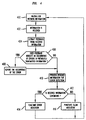
- the present invention provides a method for improving throughput of a communication system comprising: an equipment waiting for incoming information which information comprises feedback.
- the equipment receives the incoming information and extracts the feedback from the received information.
- the feedback is processed to determine whether there is an indication that information previously transmitted by the equipment is requested to be retransmitted. If so, the previous information is retransmitted by the equipment.
- the equipment then performs error detection operations on the received information to determine whether the received information is erroneous. Based on the result of the error detection operation, the equipment inserts decode status data (i.e., performs data puncture operation) into information that it is currently being transmitted by the equipment which decode status data indicate whether the received information is in error and is to be retransmitted.
- decode status data i.e., performs data puncture operation
- RX 109 of user equipment 106 receives information block 300 over forward link 102.
- Network equipment 100 begins to transmit information block 300 at time ⁇ 0 .
- At time ⁇ 1 user equipment 106 begins to transmit frame 301.
- Received information block 300 contains feedback or error correction data which is extracted by PROC 111 to determine if any previous information transmitted by user equipment 106 is to be retransmitted.
- PROC 111 processes information block 300 (i.e., performs error detection operations) to detect whether or not received information block 300 is erroneous.
- the appropriate decode status data is inserted into information currently being transmitted by user equipment 106 reducing the time it takes for information block 300 to be retransmitted thus improving the throughput of forward link 102.
- the insertion of decode status data into information being transmitted is called data puncture.
- the decode status data is interpreted as feedback by the equipment which receives the information being transmitted.
- the method of the present invention is described as being part of a CDMA wireless communication system complying with a Radio Link Protocol (RLP) that is part of the well known IS-707 standard. It will be readily obvious that the method of the present invention applies to other types of wireless communication systems such as Time Division Multiple Access (TDMA) systems.
- the present invention also applies to wireline communication systems such as Hybrid Fiber Coax (HFC) systems or copper wire telephony systems such as the well known Public Switched Telephone System (PSTN) or Synchronous Optical Network (SONET) systems that use a FEC technique.
- HFC Hybrid Fiber Coax
- PSTN Public Switched Telephone System
- SONET Synchronous Optical Network
- RX 109 receives information block 300 transmitted by TX 101.
- User equipment 106 transfers information block 300 to PROC 111 which processes the information block including decoding the information.
- Information block 300 contains information being conveyed between, for example, two users or between a user and network equipment.
- Information block 300 further contains feedback in accordance with the present invention. Feedback or error correction data is defined as information coded to indicate whether information previously transmitted by an equipment is erroneous. The previous information need not be the very last information block that was transmitted but, in general, can be the information transmitted N information blocks previously where N is an integer equal to or greater than 1.
- the feedback received by user equipment 106 indicate whether a block of information previously transmitted (N blocks earlier or 1 block earlier) by TX 107 was erroneous.
- Error correction data or feedback is represented in the form of a bit, a string of bits or in any other well known fashion.
- PROC 111 extracts the feedback from information block 300.
- the extraction of the feedback involves removing a portion of the information from a defined location within the received information block.
- a portion of the block is extracted.
- the extracted portion can be a bit, a string of bits or a block of data representing feedback.
- the location of the feedback within the received block of information can be defined, for example, by an accepted standard.
- the error correction data is located in a certain portion of a frame reserved for control information, i.e., information defined by an accepted standard for operating and controlling network equipment.
- step 406 the decoding of the feedback is performed by PROC 111 which then determines whether the decoded feedback indicate that user equipment 106 is to retransmit the last block (or N blocks earlier) of information it transmitted over reverse link 104. If the feedback indicate that an error occurred in the last block (or N blocks earlier) of information that was transmitted by user equipment 106, the occurrence of such an error is reported and acknowledged (from PROC 111 to TX 107) in step 408 and indeed the last block transmitted (or block transmitted N blocks earlier) by user equipment 106 is retransmitted at the proper time. In particular, PROC 111 causes TX 107 to retransmit the last block of information (i.e., information block 301) transmitted by user equipment 106 or block of information transmitted N blocks earlier.
- the last block of information i.e., information block 301
- step 410 user equipment 106 performs error detection operations on the received information block; that is, PROC 111 performs error detection operations on received information block 300.
- user equipment 106 completely receives information block 300 at time ⁇ ' 0 .
- ⁇ ' 0 is shown occurring prior to ⁇ 2 (i.e., start of transmission of frame 303), it can also occur after or at time ⁇ 2 .
- Error detection operations are well known detection techniques whose results are used by communication equipment to determine the integrity of received information after such information has been subjected to the distorting effects of a communication channel.
- One well known error detection technique is called Cyclic Redundancy Check (CRC).
- T' A represents the amount of time it takes for user equipment 106 (i.e., PROC 111) to process (i.e., decode and perform error detection operations) information block 300.
- PROC 111 determines whether the received block of information is erroneous based on the result of the error detection operation performed in step 410. If PROC 111 determines that the received information block is erroneous the method of the present invention moves to step 414 where PROC 111 performs a data puncture operation on information block 303.
- a data puncture operation is the insertion of decode status data into a block of information that is currently being transmitted or the very next block of information that is to be transmitted.
- PROC 111 inserts decode status data in information block 303 which decode status data is coded to be interpreted by network equipment 100 as a request for network equipment 100 to retransmit information block 300. The decode status data indicates whether or not the received information is in error.
- the location within a frame (or a block of information) of the decode status data is specifically reserved and defined, for example, by an accepted standard.
- the insertion of the decode status data can also be based on an algorithm that determines the actual location of such data within the frame being transmitted.
- the decode status data need not be inserted at the same location each time a data puncture operation is performed.
- Some communication systems use data puncture operations for other purposes such as power control.
- the method of the present invention can redefine part of an existing puncturing procedure to take advantage of a system architecture which already uses data puncturing. It should be noted that the decode status data is interpreted by network equipment 100 as feedback.
- network equipment 100 receives information block 303, decodes information block 303, extracts and decodes the feedback and retransmits (if so requested by the decoded feedback) the information (originally in frame 300) in information block 304.
- the inserted data i.e., decode status data
- the rest of the information or another possible technique is to insert the data at multiple locations. Therefore, comparing FIG. 3 to FIG.
- the method of the present invention allows an erroneous block of information to be retransmitted with a one block delay (instead of after five or more block delays) significantly improving the throughput of the communication channels (e.g., forward link 102, reverse link 104 of FIG. 1) and thus the throughput of the communication system.
- the present invention moves to step 416 where PROC 111 inserts "clear" decode status data in information block 303 indicating that the received information is not erroneous.
- the decoded information is transferred to user device 108 (e.g,. laptop computer, cellular phone, facsimile machine) and the method of the present invention returns to step 400 and waits for the next incoming information block.
Landscapes
- Engineering & Computer Science (AREA)
- Computer Networks & Wireless Communication (AREA)
- Signal Processing (AREA)
- Detection And Prevention Of Errors In Transmission (AREA)
- Communication Control (AREA)
- Mobile Radio Communication Systems (AREA)
Abstract
Description
Claims (1)
Applications Claiming Priority (2)
| Application Number | Priority Date | Filing Date | Title |
|---|---|---|---|
| US31865399A | 1999-05-25 | 1999-05-25 | |
| US318653 | 1999-05-25 |
Publications (2)
| Publication Number | Publication Date |
|---|---|
| EP1056238A2 true EP1056238A2 (en) | 2000-11-29 |
| EP1056238A3 EP1056238A3 (en) | 2001-10-24 |
Family
ID=23239060
Family Applications (1)
| Application Number | Title | Priority Date | Filing Date |
|---|---|---|---|
| EP00304059A Withdrawn EP1056238A3 (en) | 1999-05-25 | 2000-05-15 | Error recovery method for improving throughput in a communication channel |
Country Status (7)
| Country | Link |
|---|---|
| EP (1) | EP1056238A3 (en) |
| JP (1) | JP2001007789A (en) |
| KR (1) | KR20010007109A (en) |
| CN (1) | CN1275007A (en) |
| AU (1) | AU3403800A (en) |
| BR (1) | BR0001754A (en) |
| CA (1) | CA2308983A1 (en) |
Cited By (1)
| Publication number | Priority date | Publication date | Assignee | Title |
|---|---|---|---|---|
| RU2349043C2 (en) * | 2003-08-12 | 2009-03-10 | Мацусита Электрик Индастриал Ко., Лтд. | Device of radio communication and method of pilot-symbol transmission |
Families Citing this family (4)
| Publication number | Priority date | Publication date | Assignee | Title |
|---|---|---|---|---|
| CN1625861A (en) * | 2002-05-29 | 2005-06-08 | 三菱电机株式会社 | Data error control method |
| JP3845822B2 (en) * | 2003-01-23 | 2006-11-15 | ソニー・エリクソン・モバイルコミュニケーションズ株式会社 | Data receiving method and apparatus |
| JP7399944B2 (en) * | 2018-08-21 | 2023-12-18 | オッポ広東移動通信有限公司 | Wireless communication device and wireless communication method |
| CN110093990B (en) * | 2019-05-10 | 2021-03-19 | 刘亚江 | A environmental protection vacuum acoustic celotex board for fitment |
Family Cites Families (1)
| Publication number | Priority date | Publication date | Assignee | Title |
|---|---|---|---|---|
| CA1220830A (en) * | 1984-12-28 | 1987-04-21 | David S. Drynan | Transmitting sequence numbers of information in a packet data transmission system |
-
2000
- 2000-05-11 AU AU34038/00A patent/AU3403800A/en not_active Abandoned
- 2000-05-15 BR BR0001754-0A patent/BR0001754A/en not_active Application Discontinuation
- 2000-05-15 EP EP00304059A patent/EP1056238A3/en not_active Withdrawn
- 2000-05-16 CA CA 2308983 patent/CA2308983A1/en not_active Abandoned
- 2000-05-23 KR KR1020000027688A patent/KR20010007109A/en not_active Withdrawn
- 2000-05-24 JP JP2000153294A patent/JP2001007789A/en active Pending
- 2000-05-24 CN CN 00108969 patent/CN1275007A/en active Pending
Cited By (1)
| Publication number | Priority date | Publication date | Assignee | Title |
|---|---|---|---|---|
| RU2349043C2 (en) * | 2003-08-12 | 2009-03-10 | Мацусита Электрик Индастриал Ко., Лтд. | Device of radio communication and method of pilot-symbol transmission |
Also Published As
| Publication number | Publication date |
|---|---|
| EP1056238A3 (en) | 2001-10-24 |
| BR0001754A (en) | 2001-03-13 |
| JP2001007789A (en) | 2001-01-12 |
| KR20010007109A (en) | 2001-01-26 |
| CN1275007A (en) | 2000-11-29 |
| AU3403800A (en) | 2000-11-30 |
| CA2308983A1 (en) | 2000-11-25 |
Similar Documents
| Publication | Publication Date | Title |
|---|---|---|
| US7206280B1 (en) | Method and apparatus for asynchronous incremental redundancy reception in a communication system | |
| US9356739B2 (en) | Method and system for providing autonomous retransmissions in a wireless communication system | |
| US8930785B2 (en) | Method for transmitting a data block in radio communication system | |
| EP1157497B1 (en) | Data retransmission method in a voice-over-data communication system | |
| KR100871009B1 (en) | Packet transmission apparatus and packet transmission method | |
| US20070177630A1 (en) | Apparatus, method and computer program product providing retransmission utilizing multiple ARQ mechanisms | |
| US20060034285A1 (en) | WCDMA uplink HARQ operation during the reconfiguration of the TTI length | |
| KR101705768B1 (en) | Apparatus and method for operating duplication harq in mobile communication system | |
| EP1852996A2 (en) | Error detection and retransmission methods and devices for communication systems | |
| KR20020001173A (en) | Method for transferring data and data information by asynchronous wireless communication system | |
| KR20070108801A (en) | Efficient Retransmission Device and Method for High-Speed Data Processing | |
| CA2308983A1 (en) | Error recovery method for improving throughput in a communication channel | |
| KR20020019334A (en) | Method of application hybrid ARQ type Ⅱ/Ⅲ and error handling method for improvement in performence on asynchronous wireless telecommunication system | |
| WO2007022792A1 (en) | Data unit transmission method | |
| CN101296059A (en) | Error detection method for communication system, communication station and communication apparatus | |
| US20030177436A1 (en) | Transmission of encoded data packets with determination of the coding through explicit signalling by the receiver | |
| EP1745583B1 (en) | Method, system and station for communicating data packets using arq | |
| KR100709028B1 (en) | Selective retransmission of data | |
| CN1914824B (en) | Transmission power control device and method in wireless communication system | |
| CN102882664B (en) | For providing the method and system of autonomous retransmissions in a wireless communication system | |
| JP2008227666A (en) | Mobile radio equipment | |
| JP2023121408A (en) | Radio transmission system | |
| KR20070020071A (en) | Method and system for providing autonomous retransmission in wireless communication system |
Legal Events
| Date | Code | Title | Description |
|---|---|---|---|
| PUAI | Public reference made under article 153(3) epc to a published international application that has entered the european phase |
Free format text: ORIGINAL CODE: 0009012 |
|
| AK | Designated contracting states |
Kind code of ref document: A2 Designated state(s): AT BE CH CY DE DK ES FI FR GB GR IE IT LI LU MC NL PT SE Kind code of ref document: A2 Designated state(s): DE FI FR GB SE |
|
| AX | Request for extension of the european patent |
Free format text: AL;LT;LV;MK;RO;SI |
|
| PUAL | Search report despatched |
Free format text: ORIGINAL CODE: 0009013 |
|
| AK | Designated contracting states |
Kind code of ref document: A3 Designated state(s): AT BE CH CY DE DK ES FI FR GB GR IE IT LI LU MC NL PT SE |
|
| AX | Request for extension of the european patent |
Free format text: AL;LT;LV;MK;RO;SI |
|
| 17P | Request for examination filed |
Effective date: 20020412 |
|
| AKX | Designation fees paid |
Free format text: DE FI FR GB SE |
|
| 17Q | First examination report despatched |
Effective date: 20020806 |
|
| GRAP | Despatch of communication of intention to grant a patent |
Free format text: ORIGINAL CODE: EPIDOSNIGR1 |
|
| STAA | Information on the status of an ep patent application or granted ep patent |
Free format text: STATUS: THE APPLICATION IS DEEMED TO BE WITHDRAWN |
|
| 18D | Application deemed to be withdrawn |
Effective date: 20051021 |