EP1056017A1 - Computer bus extension cable - Google Patents
Computer bus extension cable Download PDFInfo
- Publication number
- EP1056017A1 EP1056017A1 EP00250143A EP00250143A EP1056017A1 EP 1056017 A1 EP1056017 A1 EP 1056017A1 EP 00250143 A EP00250143 A EP 00250143A EP 00250143 A EP00250143 A EP 00250143A EP 1056017 A1 EP1056017 A1 EP 1056017A1
- Authority
- EP
- European Patent Office
- Prior art keywords
- cable
- phy
- repeater
- extension cable
- bus extension
- Prior art date
- Legal status (The legal status is an assumption and is not a legal conclusion. Google has not performed a legal analysis and makes no representation as to the accuracy of the status listed.)
- Granted
Links
Images
Classifications
-
- G—PHYSICS
- G06—COMPUTING OR CALCULATING; COUNTING
- G06F—ELECTRIC DIGITAL DATA PROCESSING
- G06F13/00—Interconnection of, or transfer of information or other signals between, memories, input/output devices or central processing units
- G06F13/38—Information transfer, e.g. on bus
- G06F13/40—Bus structure
- G06F13/4063—Device-to-bus coupling
- G06F13/409—Mechanical coupling
-
- G—PHYSICS
- G06—COMPUTING OR CALCULATING; COUNTING
- G06F—ELECTRIC DIGITAL DATA PROCESSING
- G06F13/00—Interconnection of, or transfer of information or other signals between, memories, input/output devices or central processing units
- G06F13/38—Information transfer, e.g. on bus
- G06F13/40—Bus structure
- G06F13/4004—Coupling between buses
Definitions
- the invention relates to a bus extension cable, which connects physically two devices.
- the cable environment is a network of nodes connected by point-to-point links called physical connections.
- the physical connection consists of a port on each node's Physical Layer (PHY) and the cable between them.
- PHY Physical Layer
- a PHY can have multiple ports, which allows a branching multihop.
- the primary restriction is that nodes must be connected together as an acyclic graph, no loops.
- the cable PHY translates this physical point-to-point topology into the virtual broadcast bus expected by higher layers. The cable PHY does this by taking all data received on one port, resynchronizing it to a local clock, and repeating it on all of its other ports.
- Cable assemblies consist of two identical plug connectors joined by a length of cable material.
- the suggested maximum length is 4.5 m. This is to assure that a maximally-configured cable environment does not exceed the length over which the end-to-end signal propagation delay would exceed the allowed time. Longer cable lengths are possible if special consideration is given to the actual Serial Bus system topology to be used. In some applications, longer cable length are possible with slightly thicker cables.
- All multiple port nodes present on a Serial Bus in the cable environment are, by definition, repeater nodes. This is the minimum capability required and consists of an active physical layer.
- the PHY may be powered from the bus (via the power/ground pair in the Serial Bus cable) or from some other source.
- Repeater nodes shall:
- An extension cable with a female and a male IEEE 1394 6-pin connector is formed.
- An IEEE 1394 Physical Layer circuit is placed in the box of the female or male connector or close to it.
- For carrying this IEEE 1394 Physical Layer circuit the box of that connector is chosen, which is distant from the device to be plugged in. This circuit is powered by the power available through the cable and behaves like a repeater. By concatenating several of these "active" cables even longer distances could be managed.
- a repeater helps bridging longer distances and where power is available through the cable this invention can be used. If only very little power is required and power is not available through the cable, a battery can be mounted in the repeater box.
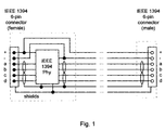
- Fig. 1 shows a bus extension cable.
- the extension cable is formed with a female and a male IEEE 1394 6-pin connector.
- An IEEE 1394 Physical Layer (PHY) circuit is placed in a box of the female connector or close to it. This circuit is powered by the power available through the cable and behaves like a repeater.
- the physical layer IC serves as a repeater in those devices, which are powered off and do not actively communicate with the other devices. In these cases the physical layer IC is powered by the power lines in the cable.
- the dashed lines indicate the housings of the connectors.
- an IEEE1394 6-pin connector there are two pins dedicated to the power supply lines Vcc and GND. The other four pins are dedicated to the data communication. There are two twisted pair transmission lines for signaling in the cable. One pair is dedicated to the data signal. The other pair is dedicated to strobe signals, which means to a specific clock signal (data strobe encoding) for synchronous serial data transfer. Also, there is an overall shield in the cable.
- the repeater can be extern of the housing but integrated in the cable and near the housing of the connector.
- its not required that the repeater is at the female connector side of the cable. It can alternatively be at the male connector side.
- IEEE 1394 Physical Layer circuits can be placed within one cable at certain distances, powered by the power available through the cable.
- the IEEE 1394 Physical Layer circuit can be powered by an external source.
- the repeater can be extern of the housing but connected to the housing/shielding of the connector.
Landscapes
- Engineering & Computer Science (AREA)
- General Engineering & Computer Science (AREA)
- Theoretical Computer Science (AREA)
- Computer Hardware Design (AREA)
- Physics & Mathematics (AREA)
- General Physics & Mathematics (AREA)
- Small-Scale Networks (AREA)
- Details Of Connecting Devices For Male And Female Coupling (AREA)
Abstract
Description
- The invention relates to a bus extension cable, which connects physically two devices.
- In the IEEE 1394 standard a cable environment is described. The cable environment is a network of nodes connected by point-to-point links called physical connections. The physical connection consists of a port on each node's Physical Layer (PHY) and the cable between them. A PHY can have multiple ports, which allows a branching multihop. The primary restriction is that nodes must be connected together as an acyclic graph, no loops. The cable PHY translates this physical point-to-point topology into the virtual broadcast bus expected by higher layers. The cable PHY does this by taking all data received on one port, resynchronizing it to a local clock, and repeating it on all of its other ports.
- Cable assemblies consist of two identical plug connectors joined by a length of cable material. The suggested maximum length is 4.5 m. This is to assure that a maximally-configured cable environment does not exceed the length over which the end-to-end signal propagation delay would exceed the allowed time. Longer cable lengths are possible if special consideration is given to the actual Serial Bus system topology to be used. In some applications, longer cable length are possible with slightly thicker cables.
- All multiple port nodes present on a Serial Bus in the cable environment are, by definition, repeater nodes. This is the minimum capability required and consists of an active physical layer. The PHY may be powered from the bus (via the power/ground pair in the Serial Bus cable) or from some other source. Repeater nodes shall:
- a) have an active physical layer, and
- b) function as an accurate signal repeater to propagate the signal state from the PHY port conditioned for reception to all other PHY ports conditioned for transmission, and
- c) participate in the cable initialization and normal arbitration phases, and be capable of functioning as the root of a Serial Bus, and
- d) reconfigure their operational characteristics in response to PHY configuration packets.
-
- It is an object of the present invention to disclose a device, that allows connections between two devices having a larger distance from each other than recommended by the standard.
- According to the invention, this object is achieved by means of the features specified in independent claim 1. Advantageous designs and developments are specified in the dependent claims.
- An extension cable with a female and a male IEEE 1394 6-pin connector is formed. An IEEE 1394 Physical Layer circuit is placed in the box of the female or male connector or close to it. For carrying this IEEE 1394 Physical Layer circuit the box of that connector is chosen, which is distant from the device to be plugged in. This circuit is powered by the power available through the cable and behaves like a repeater. By concatenating several of these "active" cables even longer distances could be managed.
- Longer cable lengths are possible compared to the specified recommended maximum IEEE 1394 6-pin cable length. Not only duplication of the cable length is possible, even multiples of the allowed length are possible. Easy handling - due to a female and a male connector the repeater is always at the right place - and simplicity of production - only one type of extension cable (if desired) - are further advantages.
- Wherever a repeater helps bridging longer distances and where power is available through the cable this invention can be used. If only very little power is required and power is not available through the cable, a battery can be mounted in the repeater box.
- Embodiments of the invention are described with reference to the accompanying drawing, which show in:
- Fig. 1
- a bus extension cable.
- Exemplary embodiments of the invention are explained in more detail in the following description.
- Fig. 1 shows a bus extension cable. The extension cable is formed with a female and a male IEEE 1394 6-pin connector. An IEEE 1394 Physical Layer (PHY) circuit is placed in a box of the female connector or close to it. This circuit is powered by the power available through the cable and behaves like a repeater. The physical layer IC serves as a repeater in those devices, which are powered off and do not actively communicate with the other devices. In these cases the physical layer IC is powered by the power lines in the cable. The dashed lines indicate the housings of the connectors.
- Within an IEEE1394 6-pin connector there are two pins dedicated to the power supply lines Vcc and GND. The other four pins are dedicated to the data communication. There are two twisted pair transmission lines for signaling in the cable. One pair is dedicated to the data signal. The other pair is dedicated to strobe signals, which means to a specific clock signal (data strobe encoding) for synchronous serial data transfer. Also, there is an overall shield in the cable.
- In an alternative embodiment, the repeater can be extern of the housing but integrated in the cable and near the housing of the connector. Of course, its not required that the repeater is at the female connector side of the cable. It can alternatively be at the male connector side.
- By concatenating several of these "active" cables even longer distances could be managed. Alternatively, more than one IEEE 1394 Physical Layer circuits can be placed within one cable at certain distances, powered by the power available through the cable.
- In a further embodiment the IEEE 1394 Physical Layer circuit can be powered by an external source.
- In another embodiment, the repeater can be extern of the housing but connected to the housing/shielding of the connector.
Claims (6)
- Bus extension cable with a female and a male connector, having data lines as well as power supply lines, characterized in, that the bus extension cable includes a repeater (PHY), which is connected to one of the connectors.
- Bus extension cable according to claim 1, wherein the repeater (PHY) is placed in the housing of the connector.
- Bus extension cable according to claim 1, wherein the repeater (PHY) is placed nearby the housing of the connector and is protected by the isolation of the cable.
- Bus extension cable according to claim 1, wherein the repeater (PHY) is connected to the shielding of the connector.
- Bus extension cable according to claim 1, wherein more than one repeater (PHY) is incorporated within the cable.
- Bus extension cable according to claim 1, wherein the repeater (PHY) is powered by an external source.
Priority Applications (1)
| Application Number | Priority Date | Filing Date | Title |
|---|---|---|---|
| EP20000250143 EP1056017B1 (en) | 1999-05-27 | 2000-05-13 | Computer bus extension cable |
Applications Claiming Priority (3)
| Application Number | Priority Date | Filing Date | Title |
|---|---|---|---|
| EP99110325A EP1056019A1 (en) | 1999-05-27 | 1999-05-27 | Computer bus extension cable |
| EP99110325 | 1999-05-27 | ||
| EP20000250143 EP1056017B1 (en) | 1999-05-27 | 2000-05-13 | Computer bus extension cable |
Publications (2)
| Publication Number | Publication Date |
|---|---|
| EP1056017A1 true EP1056017A1 (en) | 2000-11-29 |
| EP1056017B1 EP1056017B1 (en) | 2008-11-05 |
Family
ID=26072941
Family Applications (1)
| Application Number | Title | Priority Date | Filing Date |
|---|---|---|---|
| EP20000250143 Expired - Lifetime EP1056017B1 (en) | 1999-05-27 | 2000-05-13 | Computer bus extension cable |
Country Status (1)
| Country | Link |
|---|---|
| EP (1) | EP1056017B1 (en) |
Cited By (1)
| Publication number | Priority date | Publication date | Assignee | Title |
|---|---|---|---|---|
| EP2541786A1 (en) * | 2011-06-29 | 2013-01-02 | Tyco Electronics Belgium EC BVBA | Data transmission cable with integrated repeater unit and cable assembly comprising such a cable |
Citations (3)
| Publication number | Priority date | Publication date | Assignee | Title |
|---|---|---|---|---|
| US4154978A (en) * | 1977-12-08 | 1979-05-15 | Operating Systems, Inc. | Self-contained bidirectional amplifying repeater |
| US4966562A (en) * | 1988-09-06 | 1990-10-30 | The Ohio Bell Telephone Company | Single slot repeater mounting |
| WO1997006514A1 (en) * | 1995-08-10 | 1997-02-20 | Genrad Limited | Electronic diagnostic system |
-
2000
- 2000-05-13 EP EP20000250143 patent/EP1056017B1/en not_active Expired - Lifetime
Patent Citations (3)
| Publication number | Priority date | Publication date | Assignee | Title |
|---|---|---|---|---|
| US4154978A (en) * | 1977-12-08 | 1979-05-15 | Operating Systems, Inc. | Self-contained bidirectional amplifying repeater |
| US4966562A (en) * | 1988-09-06 | 1990-10-30 | The Ohio Bell Telephone Company | Single slot repeater mounting |
| WO1997006514A1 (en) * | 1995-08-10 | 1997-02-20 | Genrad Limited | Electronic diagnostic system |
Cited By (1)
| Publication number | Priority date | Publication date | Assignee | Title |
|---|---|---|---|---|
| EP2541786A1 (en) * | 2011-06-29 | 2013-01-02 | Tyco Electronics Belgium EC BVBA | Data transmission cable with integrated repeater unit and cable assembly comprising such a cable |
Also Published As
| Publication number | Publication date |
|---|---|
| EP1056017B1 (en) | 2008-11-05 |
Similar Documents
| Publication | Publication Date | Title |
|---|---|---|
| US6793539B1 (en) | Linking apparatus for stackable network devices | |
| US4951280A (en) | Method and apparatus for configuring data paths within a supernet station | |
| US5836785A (en) | Apparatus and method to uniquely identify similarly connected electrical devices | |
| JPH01173214A (en) | Optical back plane | |
| US20020144159A1 (en) | HomePNA device with the function of transmitting power over a network wire | |
| US6457091B1 (en) | PCI bridge configuration having physically separate parts | |
| US6244881B1 (en) | Connector, data processing apparatus, and network apparatus | |
| US8176224B2 (en) | Apparatus for non-disruptively disconnecting a peripheral device | |
| CN112866071A (en) | ARINC429 bus transceiving multiplexing design method | |
| EP1056017B1 (en) | Computer bus extension cable | |
| EP1056019A1 (en) | Computer bus extension cable | |
| US6091739A (en) | High speed databus utilizing point to multi-point interconnect non-contact coupler technology achieving a multi-point to multi-point interconnect | |
| JP2991081B2 (en) | Asynchronous serial communication network | |
| US6925077B1 (en) | System and method for interfacing between a media access controller and a number of physical layer devices using time division multiplexing | |
| Bracknell | Introduction to the Mil-Std-1553B serial multiplex data bus | |
| US20050068987A1 (en) | Highly configurable radar module link | |
| US6647537B1 (en) | IEEE 1394 cable connector with short circuit switch | |
| CN109804711B (en) | Modular communication device | |
| CN120321211B (en) | Multi-channel network port expansion system of communication chip and communication chip | |
| US20090122725A1 (en) | Robust networks for non-disruptively disconnecting peripheral devices | |
| KR0162760B1 (en) | How to configure interconnection network of large parallel computer | |
| CN110275848B (en) | Adapter card | |
| EP1622037B1 (en) | Integrated branching network system and joint connector | |
| Belforte et al. | Specification of the XTRP, SVT, and Level 2 Interfaces | |
| JPS6225528A (en) | Signal transmission system |
Legal Events
| Date | Code | Title | Description |
|---|---|---|---|
| PUAI | Public reference made under article 153(3) epc to a published international application that has entered the european phase |
Free format text: ORIGINAL CODE: 0009012 |
|
| AK | Designated contracting states |
Kind code of ref document: A1 Designated state(s): AT BE CH CY DE DK ES FI FR GB GR IE IT LI LU MC NL PT SE |
|
| AX | Request for extension of the european patent |
Free format text: AL;LT;LV;MK;RO;SI |
|
| 17P | Request for examination filed |
Effective date: 20010414 |
|
| AKX | Designation fees paid |
Free format text: AT BE CH CY DE DK ES FI FR GB GR IE IT LI LU MC NL PT SE |
|
| RAP1 | Party data changed (applicant data changed or rights of an application transferred) |
Owner name: THOMSON LICENSING |
|
| GRAP | Despatch of communication of intention to grant a patent |
Free format text: ORIGINAL CODE: EPIDOSNIGR1 |
|
| GRAS | Grant fee paid |
Free format text: ORIGINAL CODE: EPIDOSNIGR3 |
|
| GRAA | (expected) grant |
Free format text: ORIGINAL CODE: 0009210 |
|
| AK | Designated contracting states |
Kind code of ref document: B1 Designated state(s): AT BE CH CY DE DK ES FI FR GB GR IE IT LI LU MC NL PT SE |
|
| REG | Reference to a national code |
Ref country code: GB Ref legal event code: FG4D |
|
| REG | Reference to a national code |
Ref country code: CH Ref legal event code: EP |
|
| REG | Reference to a national code |
Ref country code: IE Ref legal event code: FG4D |
|
| REF | Corresponds to: |
Ref document number: 60040709 Country of ref document: DE Date of ref document: 20081218 Kind code of ref document: P |
|
| REG | Reference to a national code |
Ref country code: ES Ref legal event code: FG2A Ref document number: 2316337 Country of ref document: ES Kind code of ref document: T3 |
|
| PG25 | Lapsed in a contracting state [announced via postgrant information from national office to epo] |
Ref country code: AT Free format text: LAPSE BECAUSE OF FAILURE TO SUBMIT A TRANSLATION OF THE DESCRIPTION OR TO PAY THE FEE WITHIN THE PRESCRIBED TIME-LIMIT Effective date: 20081105 |
|
| PG25 | Lapsed in a contracting state [announced via postgrant information from national office to epo] |
Ref country code: FI Free format text: LAPSE BECAUSE OF FAILURE TO SUBMIT A TRANSLATION OF THE DESCRIPTION OR TO PAY THE FEE WITHIN THE PRESCRIBED TIME-LIMIT Effective date: 20081105 |
|
| PG25 | Lapsed in a contracting state [announced via postgrant information from national office to epo] |
Ref country code: DK Free format text: LAPSE BECAUSE OF FAILURE TO SUBMIT A TRANSLATION OF THE DESCRIPTION OR TO PAY THE FEE WITHIN THE PRESCRIBED TIME-LIMIT Effective date: 20081105 Ref country code: BE Free format text: LAPSE BECAUSE OF FAILURE TO SUBMIT A TRANSLATION OF THE DESCRIPTION OR TO PAY THE FEE WITHIN THE PRESCRIBED TIME-LIMIT Effective date: 20081105 |
|
| PG25 | Lapsed in a contracting state [announced via postgrant information from national office to epo] |
Ref country code: SE Free format text: LAPSE BECAUSE OF FAILURE TO SUBMIT A TRANSLATION OF THE DESCRIPTION OR TO PAY THE FEE WITHIN THE PRESCRIBED TIME-LIMIT Effective date: 20090205 Ref country code: PT Free format text: LAPSE BECAUSE OF FAILURE TO SUBMIT A TRANSLATION OF THE DESCRIPTION OR TO PAY THE FEE WITHIN THE PRESCRIBED TIME-LIMIT Effective date: 20090406 |
|
| PLBE | No opposition filed within time limit |
Free format text: ORIGINAL CODE: 0009261 |
|
| STAA | Information on the status of an ep patent application or granted ep patent |
Free format text: STATUS: NO OPPOSITION FILED WITHIN TIME LIMIT |
|
| 26N | No opposition filed |
Effective date: 20090806 |
|
| PG25 | Lapsed in a contracting state [announced via postgrant information from national office to epo] |
Ref country code: MC Free format text: LAPSE BECAUSE OF NON-PAYMENT OF DUE FEES Effective date: 20090531 |
|
| REG | Reference to a national code |
Ref country code: CH Ref legal event code: PL |
|
| PG25 | Lapsed in a contracting state [announced via postgrant information from national office to epo] |
Ref country code: CH Free format text: LAPSE BECAUSE OF NON-PAYMENT OF DUE FEES Effective date: 20090531 Ref country code: LI Free format text: LAPSE BECAUSE OF NON-PAYMENT OF DUE FEES Effective date: 20090531 |
|
| PG25 | Lapsed in a contracting state [announced via postgrant information from national office to epo] |
Ref country code: IE Free format text: LAPSE BECAUSE OF NON-PAYMENT OF DUE FEES Effective date: 20090513 |
|
| PG25 | Lapsed in a contracting state [announced via postgrant information from national office to epo] |
Ref country code: GR Free format text: LAPSE BECAUSE OF FAILURE TO SUBMIT A TRANSLATION OF THE DESCRIPTION OR TO PAY THE FEE WITHIN THE PRESCRIBED TIME-LIMIT Effective date: 20090206 |
|
| PG25 | Lapsed in a contracting state [announced via postgrant information from national office to epo] |
Ref country code: LU Free format text: LAPSE BECAUSE OF NON-PAYMENT OF DUE FEES Effective date: 20090513 |
|
| PG25 | Lapsed in a contracting state [announced via postgrant information from national office to epo] |
Ref country code: CY Free format text: LAPSE BECAUSE OF FAILURE TO SUBMIT A TRANSLATION OF THE DESCRIPTION OR TO PAY THE FEE WITHIN THE PRESCRIBED TIME-LIMIT Effective date: 20081105 |
|
| REG | Reference to a national code |
Ref country code: FR Ref legal event code: PLFP Year of fee payment: 17 |
|
| PGFP | Annual fee paid to national office [announced via postgrant information from national office to epo] |
Ref country code: ES Payment date: 20160414 Year of fee payment: 17 |
|
| REG | Reference to a national code |
Ref country code: FR Ref legal event code: PLFP Year of fee payment: 18 |
|
| REG | Reference to a national code |
Ref country code: DE Ref legal event code: R082 Ref document number: 60040709 Country of ref document: DE Representative=s name: DEHNS, DE Ref country code: DE Ref legal event code: R082 Ref document number: 60040709 Country of ref document: DE Representative=s name: HOFSTETTER, SCHURACK & PARTNER PATENT- UND REC, DE |
|
| REG | Reference to a national code |
Ref country code: FR Ref legal event code: PLFP Year of fee payment: 19 |
|
| REG | Reference to a national code |
Ref country code: ES Ref legal event code: FD2A Effective date: 20180703 |
|
| PG25 | Lapsed in a contracting state [announced via postgrant information from national office to epo] |
Ref country code: ES Free format text: LAPSE BECAUSE OF NON-PAYMENT OF DUE FEES Effective date: 20170514 |
|
| REG | Reference to a national code |
Ref country code: DE Ref legal event code: R082 Ref document number: 60040709 Country of ref document: DE Representative=s name: DEHNS, DE Ref country code: DE Ref legal event code: R081 Ref document number: 60040709 Country of ref document: DE Owner name: INTERDIGITAL CE PATENT HOLDINGS SAS, FR Free format text: FORMER OWNER: THOMSON LICENSING, BOULOGNE-BILLANCOURT, FR |
|
| PGFP | Annual fee paid to national office [announced via postgrant information from national office to epo] |
Ref country code: NL Payment date: 20190426 Year of fee payment: 20 |
|
| PGFP | Annual fee paid to national office [announced via postgrant information from national office to epo] |
Ref country code: DE Payment date: 20190418 Year of fee payment: 20 Ref country code: IT Payment date: 20190418 Year of fee payment: 20 |
|
| PGFP | Annual fee paid to national office [announced via postgrant information from national office to epo] |
Ref country code: FR Payment date: 20190419 Year of fee payment: 20 |
|
| REG | Reference to a national code |
Ref country code: NL Ref legal event code: PD Owner name: INTERDIGITAL CE PATENT HOLDINGS; FR Free format text: DETAILS ASSIGNMENT: CHANGE OF OWNER(S), ASSIGNMENT; FORMER OWNER NAME: THOMSON LICENSING S.A. Effective date: 20190903 |
|
| REG | Reference to a national code |
Ref country code: GB Ref legal event code: 732E Free format text: REGISTERED BETWEEN 20190912 AND 20190918 |
|
| PGFP | Annual fee paid to national office [announced via postgrant information from national office to epo] |
Ref country code: GB Payment date: 20190423 Year of fee payment: 20 |
|
| REG | Reference to a national code |
Ref country code: NL Ref legal event code: MK Effective date: 20200512 |
|
| REG | Reference to a national code |
Ref country code: GB Ref legal event code: PE20 Expiry date: 20200512 |
|
| PG25 | Lapsed in a contracting state [announced via postgrant information from national office to epo] |
Ref country code: GB Free format text: LAPSE BECAUSE OF EXPIRATION OF PROTECTION Effective date: 20200512 |