EP1055992A2 - Method and device for power consumption management for display unit - Google Patents
Method and device for power consumption management for display unit Download PDFInfo
- Publication number
- EP1055992A2 EP1055992A2 EP00302141A EP00302141A EP1055992A2 EP 1055992 A2 EP1055992 A2 EP 1055992A2 EP 00302141 A EP00302141 A EP 00302141A EP 00302141 A EP00302141 A EP 00302141A EP 1055992 A2 EP1055992 A2 EP 1055992A2
- Authority
- EP
- European Patent Office
- Prior art keywords
- sync signal
- signal
- display unit
- peripheral device
- power supply
- Prior art date
- Legal status (The legal status is an assumption and is not a legal conclusion. Google has not performed a legal analysis and makes no representation as to the accuracy of the status listed.)
- Withdrawn
Links
Images


Classifications
-
- G—PHYSICS
- G09—EDUCATION; CRYPTOGRAPHY; DISPLAY; ADVERTISING; SEALS
- G09G—ARRANGEMENTS OR CIRCUITS FOR CONTROL OF INDICATING DEVICES USING STATIC MEANS TO PRESENT VARIABLE INFORMATION
- G09G5/00—Control arrangements or circuits for visual indicators common to cathode-ray tube indicators and other visual indicators
- G09G5/003—Details of a display terminal, the details relating to the control arrangement of the display terminal and to the interfaces thereto
-
- G—PHYSICS
- G06—COMPUTING OR CALCULATING; COUNTING
- G06F—ELECTRIC DIGITAL DATA PROCESSING
- G06F1/00—Details not covered by groups G06F3/00 - G06F13/00 and G06F21/00
- G06F1/26—Power supply means, e.g. regulation thereof
- G06F1/32—Means for saving power
- G06F1/3203—Power management, i.e. event-based initiation of a power-saving mode
- G06F1/3206—Monitoring of events, devices or parameters that trigger a change in power modality
- G06F1/3215—Monitoring of peripheral devices
- G06F1/3218—Monitoring of peripheral devices of display devices
-
- G—PHYSICS
- G09—EDUCATION; CRYPTOGRAPHY; DISPLAY; ADVERTISING; SEALS
- G09G—ARRANGEMENTS OR CIRCUITS FOR CONTROL OF INDICATING DEVICES USING STATIC MEANS TO PRESENT VARIABLE INFORMATION
- G09G2330/00—Aspects of power supply; Aspects of display protection and defect management
- G09G2330/02—Details of power systems and of start or stop of display operation
- G09G2330/021—Power management, e.g. power saving
- G09G2330/022—Power management, e.g. power saving in absence of operation, e.g. no data being entered during a predetermined time
-
- G—PHYSICS
- G09—EDUCATION; CRYPTOGRAPHY; DISPLAY; ADVERTISING; SEALS
- G09G—ARRANGEMENTS OR CIRCUITS FOR CONTROL OF INDICATING DEVICES USING STATIC MEANS TO PRESENT VARIABLE INFORMATION
- G09G2370/00—Aspects of data communication
- G09G2370/04—Exchange of auxiliary data, i.e. other than image data, between monitor and graphics controller
- G09G2370/045—Exchange of auxiliary data, i.e. other than image data, between monitor and graphics controller using multiple communication channels, e.g. parallel and serial
Definitions
- the present invention relates to a method and a device for power management in a display unit.
- a display unit such as a PC monitor which uses a CRT for information display.
- the electrical energy consumed by a video display is mostly, if not completely, convened into heat energy that warms up the room in which the display device is placed.
- the conversion of electrical energy into heat energy in this way is indeed wasteful, especially when the video display is not being used to provide any visual information.
- PC monitors are generally provided with a power saving scheme such that when the PC is not in use after a certain period of time, the power supply in the monitor will be switched from a regular "ON" mode to a suspend mode or a stand-by mode to save energy.
- DPMS VESA Display Power Management Signaling
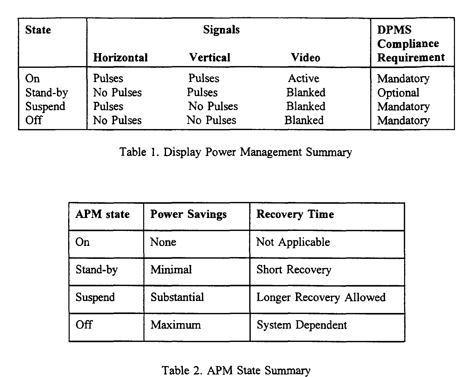
- the video display is put into different energy-saving states by means of a coded message, based on the presence of the vertical sync and horizontal sync signals, as shown in Table 1. With the presence or absence of the video sync signals, there are four possible power levels to be set. The ON state is referred to when the display is in full operation, being used to show an image.
- Integrated display units in addition to the video display, some audio-visual components such as audio amplifier, speakers, microphone, camera and telephone handset may also be included. Integrated display units are also referred to as "multimedia terminals". Like the CRT, the added-on components require adequate electrical power to function properly. Currently, audio components and the camera in an integrated display unit draw power from separate power supplies. These extra power supplies not only increase the cost of an integrated display unit, but also require more space and more power outlets. Therefore, it is desirable to allow these added-on peripheral devices to share a power supply with the CRT. With these added-on components, however, it may not be adequate to switch the power supply to different power saving states based solely on the presence or absence of the video sync signals.
- the PC may be completely inactive for a long period of time while the camera is still taking pictures of the conference participants and the audio components are still processing the conversation of the participants.
- the power supply in the integrated display unit should not be caused to enter a low power output state that may render the camera and the audio components non-operational.
- USB Universal Serial Bus
- the power supply in the integrated display unit should be controlled differently.
- the video display in an integrated display unit is also used to display the images acquired by an added-on camera, the image signals from the camera should also be considered as part of the video sync signals.
- embodiments of the present invention provide a method and a device to reduce the consumption of electrical power by a display unit and to make power management more practical.
- Embodiments of the invention achieve the foregoing by reducing the number of power supplies in an integrated display unit, preferably to one, and by providing a power management strategy based on the signals associated with the peripheral devices as well as the video sync signals.
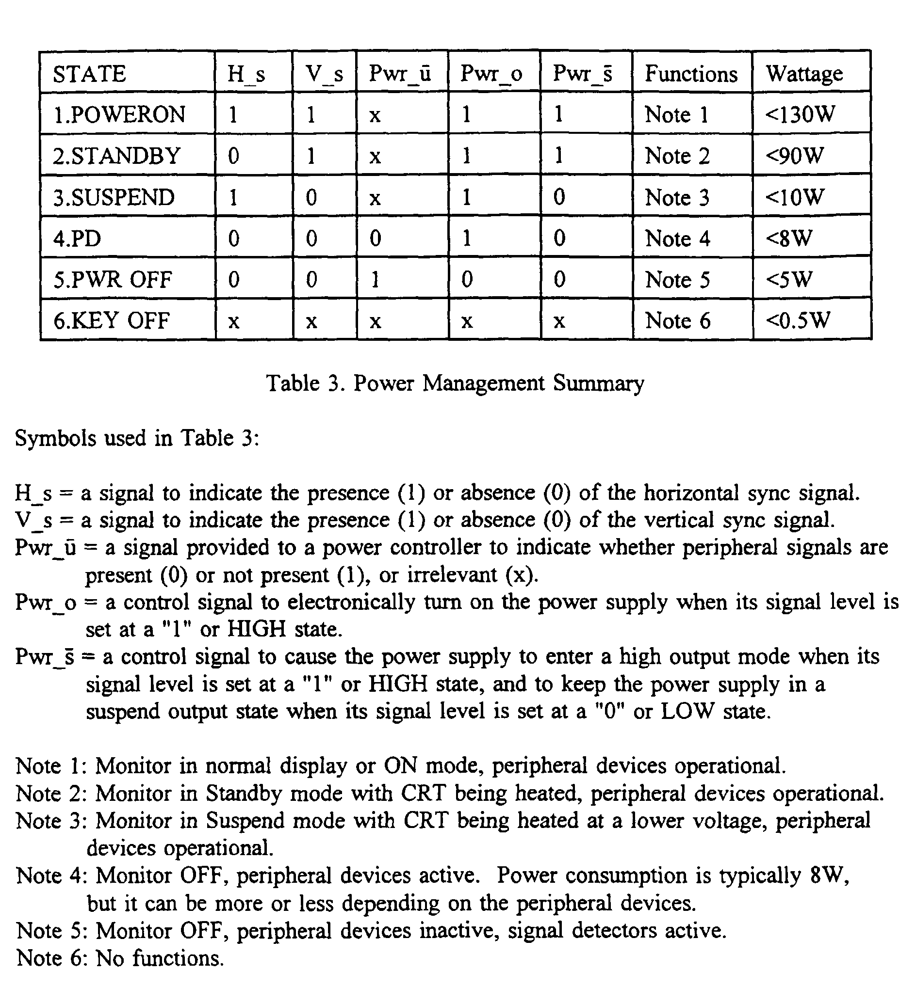
- the power management strategy is in compliance with the VESA DPMS Standard, as summarised in Table 3.
- the implementation of different power consumption states is determined by the presence of the various signals sensed by a plurality of signal detectors in the integrated display unit as described below:
- the POWER ON state is implemented when both the horizontal sync signal and the vertical sync signal are present. In this state, video images are shown on the display and the power consumption for example which follows is about 130W.
- the STANDBY state is implemented when the vertical sync signal is present but the horizontal sync signal is not present. Even though no video image is shown, the CRT remains heated for quick recovery.
- the power consumption is reduced to about 90W by switching video power amplifier off thereby blanking video output.
- the SUSPEND state is implemented when the horizontal sync signal is present but the vertical sync signal is not present. No video image is shown.
- the CRT is heated at a much lower voltage level to save energy and deflection is tuned off. The total power consumption is thereby further reduced to about 10 W.
- the PD state is implemented when signals associated with one or more peripheral devices, including a USB signal, are present but both the horizontal sync signal and the vertical sync signal are absent.
- the CRT is not heated.
- Power consumption is typically 8W, but it can be more or less depending on the peripherals in the integrated display unit.
- the PWR OFF state is implemented when no incoming signals are present.
- the power consumption of about 5W is mainly for keeping signal detectors active. If there is an audio preamplifier in the integrated display unit, it is preferable to keep the preamplifier operational. However, generally this is not required.
- the power supply is caused to enter different output modes.
- the output modes include at least a high-output mode and a suspend output mode.
- the power supply is in the high-output mode when the power consumption level is either at the POWER ON or the STANDBY state.
- the power supply is in the suspend output mode when the power consumption level is either at the SUSPEND or the PD state.
- the power supply is caused to enter different output modes based on the presence of various signals as described in the following:
- the power supply is caused to enter the high output mode whenever the vertical sync signal is present
- control signals are produced by a variety of signal detectors which sense the presence of the video sync signals and the peripheral signals.
- the Pwr_ u signal is set at a "0" or LOW state when any peripheral signal is present, and at a "1" or HIGH state when no peripheral signals are present.
- the Pwr_o signal is set at a "1" or HIGH state when any of the horizontal sync signal, the vertical sync signal and the peripheral signal is present, and at a "0" or LOW state when none of these signals are present.
- the Pwr_o signal is set at a "1" or HIGH state only when the vertical sync signal is present
- the Pwr_ s signal is set at a "1" or HIGH state only when the vertical sync signal is present
- Figure 1 illustrates a block diagram showing some electronic components for detecting incoming signals and controlling a power supply.
- a number of peripheral detectors being used to detect or sense the presence of different peripheral signals.
- an audio detector 10 is used to detect audio signals 110 and to provide a signal 112 to a logic circuit 40 , indicating whether audio signals are present.
- a digital signal detector 20 is used to detect a signal 120 which indicates whether a USB cable or other digital communication means is connected to the CPU or the integrated display unit. The digital signal detector 20 provides a signal 122 to the logic circuit 40 accordingly.
- one or more PD detectors 30 may be used to detect the presence of other peripheral signals 132 associated with other peripheral devices, such as cameras and telephones, and to provide a signal 132 to the logic circuit 40 .
- the logic circuit 40 "notifies” a micro-controller 50 the presence of such signals by means of a Pwr_ u signal 142 .
- the Pwr_ u signal is set at a "0" or LOW state when peripheral signals are present and at a "1" or HIGH state otherwise.
- the micro-controller 50 Based on the status of the Pwr_ u signal 142 and the video sync signals 144 and 146 which are provided through a VGA connector 11 , the micro-controller 50 provides different Pwr_o signal 150 and Pwr_ s signal 152 to the power supply 60 .
- the Pwr_o signal 150 is used to electronically turn the power supply 60 on or off.
- the Pwr_o signal 150 turns on the power supply 60 when it is set at a "1" or HIGH state, indicating that one or more signals associated with the peripheral devices and the video display are present.
- the Pwr_ s signal 152 is used to cause the power supply 60 to enter different output modes.
- the Pwr_ s signal 152 being set a "1" or HIGH state only when the vertical sync signal is present, causes the power supply to enter a high-output mode. Otherwise, the power supply is in a suspend output mode. This output mode is implemented even when no images are shown on the monitor. However, background music may be playing, for example. In that case, a certain level of power is needed to supply electrical power to the speakers on the integrated display and, therefore, the power supply must be turned on.
- the power supply After the power supply has been electronically turned on, it can be caused to enter the high-output mode or in the suspend output mode, depending on the power saving scheme.
- Table 3 whenever the vertical sync signal is present, the power consumption is either at the POWER ON state or the STANDBY state and the power supply must be caused to enter the high-output mode in order to heat up the CRT properly.
- the V_s is "1" or HIGH
- the Pwr_ s signal 152 is always HIGH, causing the power supply to enter the high-output mode.
- the SUSPEND power consumption state is implemented to save more energy. The same is true when only the peripheral signals are present. When no incoming signals are present, the power supply is electronically turned off.
- Connector 21 can be a USB connector, for example.
- the micro-controller 50 receives power management commands from the PC or CPU.
- the power management commands can be sent to an integrated display unit in the form of digital data via USB BUS and/or other digital communication means to implement the power consumption states. Therefore, there may not be necessary to send the video sync signals to the micro-controller 50 and the VGA connector 11 can be removed, if so desired.
- audio signals 110 can be also conveyed to the integrated display unit via USB BUS through USB connector 21 .
- the audio detector 10 is no longer needed for detecting incoming audio signals.
- the Pwr_ u signal can be generated by the micro-controller 50, or by the logic circuit 40 when the +5V voltage level associated with the USB connection is detected by the digital signal detector 20 .
- FIG. 2 illustrates a schematic diagram of a power supply that may be caused to enter different output modes.
- the power supply 60 shown in Figure 2 is a flyback-type switched mode power supply, also known as a switching power supply.
- a filter/rectifier unit 62 to convert an AC line voltage 160 ( MAIN IN ) into a DC component.
- a Pulsed Width Modulation (PWM) stage 66 is used to provide chopped voltage signals to a transformer/power stage 64 which produces an isolated voltage output 162 ( POWER OUT ).
- a voltage divider R1 , R2
- R1 , R2 is used to provide a feedback signal to an isolation feedback unit 68 , which is used to control the pulse width of the PWM stage 66 .
- the output voltage 162 is controllable by the feedback voltage.
- the power supply there are two transistor switches SW1 and SW2 to control the power output.
- SW1 is closed to electronically turn on the power supply when the Pwr_o signal 150 is set at a "1" or HIGH state. At this state, when both SW1 and SW2 are closed, the power supply is caused to enter the high-output mode and the voltage output 162 is typically 180V, for example.
- the power supply When SW1 is closed but SW2 is open, the power supply is caused to enter the suspend output mode and the voltage output 162 is substantially equal to 140V, for example. At this mode, the output voltage is set at a low level but is sufficient to preheat the CRT and to allow the peripheral devices to function properly. But when the vertical sync signal is present, it is required that either the POWER ON or STANDBY power consumption state be implemented.
- V_s When V_s is HIGH, Pwr_ s is also HIGH, causing switch SW2 to be closed.
- the feedback voltage via voltage divider R1 and R2 , provided to the isolation feedback unit 68 is reduced. Consequently, the power supply "assumes" that the output voltage 162 is too low, and the isolation feedback unit 68 causes the PWM stage 66 to increase the pulse width or the voltage chopping rate, thereby raising the output voltage 162 .
- both Pwr_o signal 150 and the Pwr_ s signal 152 are LOW, keeping both SW1 and SW2 open. In that case, the power supply is electronically turned off, and the output voltage 162 is dropped substantially to 20V, for example. The power consumption is now in the PWR OFF state. Some power is still needed to keep all the peripheral detectors 10 , 20 , 30 , the logic circuit 40 and the micro-controller 50 active so as to allow these components to sense the incoming signals.
- the voltage output 162 is 0V when the power key is turned off (the KEY OFF state in Table 3).
- FIG 3 illustrates a simplistic representation of audio signals.
- Audio signals mainly carry voice or music.
- audio signals 110 are LOW when voice or music is present.
- the signal level is HIGH for a relatively long period of time, it is safe to assume that there are no incoming audio signals.
- music and conversation have silent periods and it may not be desirable to switch off the power supply whenever audio signals are absent. It is, therefore, preferable to allow the power supply to be kept on for a certain period of time, from a few seconds to 1 minute, to cover the silent period.
- FIG. 4 illustrates a representative circuit for detecting peripheral signals.
- an audio detector 10 and a USB detector 20 .
- capacitor C1 in block 41 (which is equivalent to the logic circuit 40 in Figure 1) is charged up to +5V.
- the Pwr_ u signal 142 is set at a "1" or HIGH state. If a USB cable is now connected to the integrated display and a +5V signal level, or Vcc from an upstream port, is present as signal 120, the signal level 122 at the output of transistor T4 drops substantially to 0V, discharging capacitor C1 and setting the Pwr_ u signal 142 at a "0" or LOW state. Consequently, the power supply is electronically turned on.
- the audio detector 10 when audio signals are present as signal 110 , the audio detector 10 is biased via resistors R10 and R12 .
- the audio signals, as amplified by transistors T1 are provided to transistor T2 which is biased to rectify audio signals.
- Transistor T3 makes current gain, effectively grounding signal 112 and causing C1 to discharge.
- the output stages of audio detector 10 and the USB detector 20 are open collector type ( T3 , T4 , etc). It is possible to connect several detectors in parallel using the same pull-up resistor R14 in block 41 .
Landscapes
- Engineering & Computer Science (AREA)
- Theoretical Computer Science (AREA)
- Physics & Mathematics (AREA)
- General Physics & Mathematics (AREA)
- Computer Hardware Design (AREA)
- General Engineering & Computer Science (AREA)
- Controls And Circuits For Display Device (AREA)
- Power Sources (AREA)
Abstract
Description
Claims (26)
- In a display unit having a video display for displaying images, at least one peripheral device having a first signal associated therewith, and a power supply to supply electrical power to the video display and said at least one peripheral device, wherein the video display uses a horizontal sync signal and a vertical sync signal for the synchronization of the displayed images, a method for reducing the power consumption of the integrated display unit by implementing a plurality of power consumption states, each state having a different level of power consumption, said method comprising the steps of:sensing the presence of the horizontal sync signal, the vertical sync signal and the first signal; anddetermining the power consumption state to be implemented based on the presence of the horizontal sync signal, the vertical sync signal and the first signal.
- The method of claim 1 wherein the power consumption states includes a first state, a second state, a third state, a fourth state and a fifth state in the order of the power consumption level wherein the fifth state has the lowest level of power consumption, and whereinthe first state is implemented when both the horizontal sync signal and the vertical sync signal are present;the second state is implemented when the vertical sync signal is present and the horizontal sync signal is not present;the third state is implemented when the horizontal sync signal is present and the vertical sync signal is not present;the fourth state is implemented when the first signal is present but both the horizontal sync signal and the vertical sync signal are not present; andthe fifth state is implemented when none of the horizontal sync signal, and vertical sync signal and the first signal are present.
- The method of claim 1 or 2, wherein said at least one peripheral device comprises an audio device and said first signal comprises audio signals.
- The method of any preceding claim, wherein said at least one peripheral device comprises a USB connection means and said first signal comprises a voltage level associated with the USB connection means.
- The method of any preceding claim, wherein at least one peripheral device comprises a USB connection means, and the power consumption state to be implemented is signalled via said USB connection means to the integrated display unit.
- The method any preceding claim, wherein the power consumption states are associated with at least two output modes of the power supply, said output modes including a high output mode and a suspend output mode and wherein the power supply is caused to enter the high output mode when the vertical sync signal is present; and the power supply is caused to enter the suspend output mode when the vertical sync signal is not present but either or both of the horizontal sync signal and the first signal are present.
- The method any preceding claim, wherein the presence of vertical sync signal and/or horizontal sync signal is signalled to the integrated display unit via a USB connection means.
- The method of claim 3, wherein said audio signals are provided to the display unit via a USB connection means.
- In a display unit having a video display for displaying images, at least one peripheral device, and a power supply to supply electrical power to the video display and said at least one peripheral device, wherein the video display uses a horizontal sync signal and a vertical sync signal for the synchronization of the displayed images and wherein said at least one peripheral device uses a first signal to carry out a function associated with said peripheral device, a method for reducing the power consumption of the integrated display unit by causing the power supply to enter different output modes comprising the steps of:sensing the presence of the horizontal sync signal, the vertical sync signal and the first signal;causing the power supply to enter different output modes based on the presence of the horizontal sync signal, the vertical sync signal and the first signal.
- The method of claim 9 wherein said at least one peripheral device comprises a USB connection means, and the presence of the horizontal sync signal and the vertical sync signal is signaled to the integrated display unit via said USB connection means.
- The method of claim 9 or 10, wherein the power supply is caused to enter a high output mode when the vertical sync signal is present and the power supply is caused to enter a suspend output mode when the vertical sync signal is are not present but either or both of the horizontal sync signal and the first signal are present.
- In a display unit having a video display for displaying images, at least one peripheral device, and a power supply to supply electrical power to the video display and said at least one peripheral device, wherein the display uses a horizontal sync signal and a vertical sync signal for the synchronization of the displayed images and wherein said at least one peripheral device has a first signal associated with said peripheral device, wherein the power supply is caused to enter different output modes for reducing power consumption of the integrated display unit, a device for effecting the reduction of the power consumption comprising:means for sensing the presence of the horizontal sync signal, the vertical sync signal and the first signal; andan electronic circuit to determine the output modes based on the presence of the horizontal sync signal, the vertical sync signal and the first signal.
- The device of claim 12 wherein the power supply is caused to enter a high output mode when the vertical sync signal is present and the power supply is caused to enter a suspend output mode when the vertical sync signal is not present but either or both of the horizontal sync signal and the first signal are present.
- The device of claim 12 or 13, wherein said sensing means comprises a micro-controller.
- The device of any one of claims 12 to 14, wherein said at least one peripheral device comprises an audio device and said first signal comprises audio signals, and said sensing means comprises an audio signal detector.
- The device of any one of claims 12 to 15, wherein said at least one peripheral device comprises a USB connection means and said first signal comprises a voltage level associated with the USB connection means, and said sensing means comprises a USB detector.
- The device of any one of claims 12 to 16, wherein said at least one peripheral device comprises a USB connection means and the output modes are effected by a signal provided via said USB connection means to the integrated display unit.
- A display unit having a video display for displaying images, wherein the display uses a horizontal sync signal and a vertical sync signal for the synchronisation of the displayed images, said display unit comprising:a power supply which is caused to enter different output modes for reducing power consumption of the display unit; anda digital communication means for signalling the presence of sync signals or data indicating power save states to cause the power supply to enter different output modes.
- The display unit of claim 18, further comprising at least one peripheral device having a first signal associated therewith.
- The display unit of claim 19, wherein said at least one peripheral device comprises an audio device and said first signal comprises audio signals.
- The display unit of claim 20,wherein said audio signals are provided to the display unit via said digital communication means.
- The display unit of any one of claims 18 to 21, further comprising a micro-controller to receive signals for said digital communication means.
- The display unit of any one of claims 18 to 22, wherein said digital communication means comprises a USB connection means.
- A method according to any one of claims 1 to 11, said display unit comprising an integrated display unit.
- A device according to any one of claims 12 to 17, said display unit comprising an integrated display unit.
- A display unit according to any one of claims 18 to 23, comprising an integrated display unit.
Applications Claiming Priority (2)
| Application Number | Priority Date | Filing Date | Title |
|---|---|---|---|
| US09/320,618 US6473078B1 (en) | 1999-05-26 | 1999-05-26 | Method and device for power consumption management of an integrated display unit |
| US320618 | 1999-05-26 |
Publications (2)
| Publication Number | Publication Date |
|---|---|
| EP1055992A2 true EP1055992A2 (en) | 2000-11-29 |
| EP1055992A3 EP1055992A3 (en) | 2002-01-09 |
Family
ID=23247207
Family Applications (1)
| Application Number | Title | Priority Date | Filing Date |
|---|---|---|---|
| EP00302141A Withdrawn EP1055992A3 (en) | 1999-05-26 | 2000-03-16 | Method and device for power consumption management for display unit |
Country Status (2)
| Country | Link |
|---|---|
| US (1) | US6473078B1 (en) |
| EP (1) | EP1055992A3 (en) |
Cited By (2)
| Publication number | Priority date | Publication date | Assignee | Title |
|---|---|---|---|---|
| EP1653371A3 (en) * | 2004-11-02 | 2007-10-31 | GILARDONI S.p.A. | Electronic system for the transfer of digital data strictly in real time |
| EP2006833A1 (en) * | 2007-06-05 | 2008-12-24 | Samsung Electronics Co., Ltd. | Display apparatus and method for notifying user of state of external device |
Families Citing this family (31)
| Publication number | Priority date | Publication date | Assignee | Title |
|---|---|---|---|---|
| CN1187669C (en) * | 1999-09-22 | 2005-02-02 | 索尼公司 | Information processor, display control method, and recorded medium |
| KR100753089B1 (en) * | 1999-12-20 | 2007-08-31 | 삼성전자주식회사 | Control Method of Image Display Equipment with Multiple Signal Sources |
| JP2002072990A (en) * | 2000-06-12 | 2002-03-12 | Sharp Corp | Image display system and display device |
| JP2002026801A (en) * | 2000-07-05 | 2002-01-25 | Toshiba Corp | Wireless communication terminal |
| KR100366309B1 (en) * | 2000-09-29 | 2002-12-31 | 삼성전자 주식회사 | A power-saving circuit in a digital video signal display system |
| TW553431U (en) * | 2001-09-28 | 2003-09-11 | Animation Technologies Inc | Expansion back clamp having image input and output function |
| US7496357B2 (en) * | 2002-03-04 | 2009-02-24 | At&T Intellectual Property I, L.P. | Automated telephone assistant device and associated methods |
| JP3795442B2 (en) * | 2002-09-11 | 2006-07-12 | Necディスプレイソリューションズ株式会社 | Image display system |
| US7245272B2 (en) * | 2002-10-19 | 2007-07-17 | Via Technologies, Inc. | Continuous graphics display for dual display devices during the processor non-responding period |
| US7786988B2 (en) | 2003-07-16 | 2010-08-31 | Honeywood Technologies, Llc | Window information preservation for spatially varying power conservation |
| US7580033B2 (en) * | 2003-07-16 | 2009-08-25 | Honeywood Technologies, Llc | Spatial-based power savings |
| US7602388B2 (en) * | 2003-07-16 | 2009-10-13 | Honeywood Technologies, Llc | Edge preservation for spatially varying power conservation |
| US7663597B2 (en) | 2003-07-16 | 2010-02-16 | Honeywood Technologies, Llc | LCD plateau power conservation |
| US20060020906A1 (en) * | 2003-07-16 | 2006-01-26 | Plut William J | Graphics preservation for spatially varying display device power conversation |
| US7583260B2 (en) | 2003-07-16 | 2009-09-01 | Honeywood Technologies, Llc | Color preservation for spatially varying power conservation |
| US7714831B2 (en) | 2003-07-16 | 2010-05-11 | Honeywood Technologies, Llc | Background plateau manipulation for display device power conservation |
| TWI240559B (en) * | 2004-04-16 | 2005-09-21 | Realtek Semiconductor Corp | Signal transmitter and driving method thereof |
| US20050249699A1 (en) * | 2004-05-05 | 2005-11-10 | Stoff Jesse A | Immunodynamic complexes and methods for using and preparing such complexes |
| US20060080461A1 (en) * | 2004-06-02 | 2006-04-13 | Wilcox Jeffrey R | Packet exchange for controlling system power modes |
| WO2006030702A1 (en) * | 2004-09-15 | 2006-03-23 | Sharp Kabushiki Kaisha | Display, viewing angle controller and electronic apparatus |
| US7571313B2 (en) * | 2004-12-28 | 2009-08-04 | Motorola, Inc. | Authentication for Ad Hoc network setup |
| TWI249350B (en) * | 2004-12-30 | 2006-02-11 | Tatung Co Ltd | Control circuit and method thereof for reducing power consumption of a display device |
| US7760210B2 (en) * | 2005-05-04 | 2010-07-20 | Honeywood Technologies, Llc | White-based power savings |
| US7602408B2 (en) | 2005-05-04 | 2009-10-13 | Honeywood Technologies, Llc | Luminance suppression power conservation |
| KR100763948B1 (en) * | 2005-07-12 | 2007-10-05 | 삼성전자주식회사 | Display device with USB hub |
| JP4339319B2 (en) * | 2005-09-29 | 2009-10-07 | シャープ株式会社 | Display device and electronic device |
| KR20080047811A (en) * | 2006-11-27 | 2008-05-30 | 삼성전자주식회사 | Display system including image processing apparatus, Display apparatus and display method connected to image processing apparatus |
| DE202007018449U1 (en) * | 2007-11-02 | 2008-10-02 | Fujitsu Siemens Computers Gmbh | Electronic device, computer and arrangement |
| US10437761B2 (en) * | 2015-04-17 | 2019-10-08 | Hewlett-Packard Development Company, L.P. | Universal serial bus management |
| US10504204B2 (en) | 2016-07-13 | 2019-12-10 | Semiconductor Energy Laboratory Co., Ltd. | Electronic device |
| KR102486450B1 (en) * | 2021-08-30 | 2023-01-06 | (주)드림어스컴퍼니 | Method and Apparatus for Outputting Sound Source to Minimize Power Consumption |
Family Cites Families (15)
| Publication number | Priority date | Publication date | Assignee | Title |
|---|---|---|---|---|
| US5396635A (en) * | 1990-06-01 | 1995-03-07 | Vadem Corporation | Power conservation apparatus having multiple power reduction levels dependent upon the activity of the computer system |
| US5821924A (en) | 1992-09-04 | 1998-10-13 | Elonex I.P. Holdings, Ltd. | Computer peripherals low-power-consumption standby system |
| US5389952A (en) | 1992-12-02 | 1995-02-14 | Cordata Inc. | Low-power-consumption monitor standby system |
| KR950010897B1 (en) * | 1993-08-06 | 1995-09-25 | 삼성전자주식회사 | Method and control device for generating power management signal of computer peripheral device in computer system |
| KR100214381B1 (en) | 1996-04-16 | 1999-08-02 | 구자홍 | BNC, D-SUB signal automatic switching circuit of monitor |
| KR100189781B1 (en) | 1996-05-07 | 1999-06-01 | 윤종용 | Display device and its power supply control method |
| KR100193737B1 (en) * | 1996-07-19 | 1999-06-15 | 윤종용 | Display device and its power supply control method |
| KR100225057B1 (en) * | 1996-07-23 | 1999-10-15 | 윤종용 | Control apparatus and method for power supply of monitor having audio system |
| KR100224085B1 (en) | 1996-08-14 | 1999-10-15 | 윤종용 | Power saving display device and method for controlling power thereof |
| KR100283572B1 (en) | 1997-02-24 | 2001-03-02 | 윤종용 | How to Display DPMS on Display Device Using OSD |
| US5919264A (en) * | 1997-03-03 | 1999-07-06 | Microsoft Corporation | System and method for using data structures to share a plurality of power resources among a plurality of devices |
| KR100303078B1 (en) * | 1997-05-12 | 2001-11-30 | 윤종용 | Power Management Device and Method at Power Off |
| KR19980066384U (en) * | 1997-05-16 | 1998-12-05 | 윤종용 | Low power circuit using electronic switch of display monitor |
| EP0901062A1 (en) | 1997-06-11 | 1999-03-10 | Compaq Computer Corporation | Blinking bezel led from firmware when CPU is in sleep mode |
| KR100281529B1 (en) * | 1998-04-11 | 2001-02-15 | 윤종용 | Power supply control circuit of display device with universal serial bus device |
-
1999
- 1999-05-26 US US09/320,618 patent/US6473078B1/en not_active Expired - Lifetime
-
2000
- 2000-03-16 EP EP00302141A patent/EP1055992A3/en not_active Withdrawn
Cited By (2)
| Publication number | Priority date | Publication date | Assignee | Title |
|---|---|---|---|---|
| EP1653371A3 (en) * | 2004-11-02 | 2007-10-31 | GILARDONI S.p.A. | Electronic system for the transfer of digital data strictly in real time |
| EP2006833A1 (en) * | 2007-06-05 | 2008-12-24 | Samsung Electronics Co., Ltd. | Display apparatus and method for notifying user of state of external device |
Also Published As
| Publication number | Publication date |
|---|---|
| EP1055992A3 (en) | 2002-01-09 |
| US6473078B1 (en) | 2002-10-29 |
Similar Documents
| Publication | Publication Date | Title |
|---|---|---|
| US6473078B1 (en) | Method and device for power consumption management of an integrated display unit | |
| USRE45979E1 (en) | Power-saving circuit and method for a digital video display device | |
| US5938770A (en) | Display apparatus for computer system | |
| US9152186B2 (en) | Notebook computer and cell phone assembly | |
| CN109831700B (en) | A standby mode switching method, device, electronic device and storage medium | |
| CN100483329C (en) | Method for controlling video display apparatus having multiple signal sources | |
| US7000127B2 (en) | Power saving circuit for display system | |
| US7050049B2 (en) | Display device and method of controlling the same | |
| JP2010511367A (en) | Power supply control device | |
| US7478254B2 (en) | Switching power supply device with power on from standby sequence that includes reconnecting dummy resistor to large load power supply line | |
| KR20060063731A (en) | Standby power cut-off device and multi-outlet using the same | |
| US6424875B1 (en) | Method and circuit for controlling power of audio processor in monitor | |
| KR102051949B1 (en) | A controling method of monitor apparatus for saving the power by controling Sync signals | |
| US7595847B2 (en) | Audio/video playback control system of liquid crystal display television | |
| US8782715B2 (en) | Communication apparatus | |
| US11783786B2 (en) | Electronic apparatus | |
| MXPA00004693A (en) | Image displaying device. | |
| CN213638004U (en) | Multimedia intelligent conference machine control system | |
| JP2007274065A (en) | Video output device | |
| US6769070B1 (en) | Standby circuit for digital display monitor | |
| US12190760B2 (en) | Display system and power-saving method thereof | |
| KR100306643B1 (en) | power control circuit of display system | |
| KR19990003854A (en) | Minimizing power of display device and device using same | |
| JPH11265235A (en) | Computer system and power supply control device | |
| JP2009032351A (en) | Recording and reproducing device |
Legal Events
| Date | Code | Title | Description |
|---|---|---|---|
| PUAI | Public reference made under article 153(3) epc to a published international application that has entered the european phase |
Free format text: ORIGINAL CODE: 0009012 |
|
| AK | Designated contracting states |
Kind code of ref document: A2 Designated state(s): AT BE CH CY DE DK ES FI FR GB GR IE IT LI LU MC NL PT SE Kind code of ref document: A2 Designated state(s): DE FR GB IT |
|
| AX | Request for extension of the european patent |
Free format text: AL;LT;LV;MK;RO;SI |
|
| PUAL | Search report despatched |
Free format text: ORIGINAL CODE: 0009013 |
|
| AK | Designated contracting states |
Kind code of ref document: A3 Designated state(s): AT BE CH CY DE DK ES FI FR GB GR IE IT LI LU MC NL PT SE |
|
| AX | Request for extension of the european patent |
Free format text: AL;LT;LV;MK;RO;SI |
|
| 17P | Request for examination filed |
Effective date: 20020618 |
|
| AKX | Designation fees paid |
Free format text: DE FR GB IT |
|
| 17Q | First examination report despatched |
Effective date: 20040303 |
|
| STAA | Information on the status of an ep patent application or granted ep patent |
Free format text: STATUS: THE APPLICATION HAS BEEN WITHDRAWN |
|
| 18W | Application withdrawn |
Effective date: 20130116 |