EP1055574A2 - Brake control system - Google Patents
Brake control system Download PDFInfo
- Publication number
- EP1055574A2 EP1055574A2 EP00111180A EP00111180A EP1055574A2 EP 1055574 A2 EP1055574 A2 EP 1055574A2 EP 00111180 A EP00111180 A EP 00111180A EP 00111180 A EP00111180 A EP 00111180A EP 1055574 A2 EP1055574 A2 EP 1055574A2
- Authority
- EP
- European Patent Office
- Prior art keywords
- wheel
- speed
- abnormal
- abnormality
- vehicle body
- Prior art date
- Legal status (The legal status is an assumption and is not a legal conclusion. Google has not performed a legal analysis and makes no representation as to the accuracy of the status listed.)
- Granted
Links
Images




Classifications
-
- B—PERFORMING OPERATIONS; TRANSPORTING
- B60—VEHICLES IN GENERAL
- B60T—VEHICLE BRAKE CONTROL SYSTEMS OR PARTS THEREOF; BRAKE CONTROL SYSTEMS OR PARTS THEREOF, IN GENERAL; ARRANGEMENT OF BRAKING ELEMENTS ON VEHICLES IN GENERAL; PORTABLE DEVICES FOR PREVENTING UNWANTED MOVEMENT OF VEHICLES; VEHICLE MODIFICATIONS TO FACILITATE COOLING OF BRAKES
- B60T8/00—Arrangements for adjusting wheel-braking force to meet varying vehicular or ground-surface conditions, e.g. limiting or varying distribution of braking force
- B60T8/17—Using electrical or electronic regulation means to control braking
- B60T8/173—Eliminating or reducing the effect of unwanted signals, e.g. due to vibrations or electrical noise
-
- B—PERFORMING OPERATIONS; TRANSPORTING
- B60—VEHICLES IN GENERAL
- B60T—VEHICLE BRAKE CONTROL SYSTEMS OR PARTS THEREOF; BRAKE CONTROL SYSTEMS OR PARTS THEREOF, IN GENERAL; ARRANGEMENT OF BRAKING ELEMENTS ON VEHICLES IN GENERAL; PORTABLE DEVICES FOR PREVENTING UNWANTED MOVEMENT OF VEHICLES; VEHICLE MODIFICATIONS TO FACILITATE COOLING OF BRAKES
- B60T8/00—Arrangements for adjusting wheel-braking force to meet varying vehicular or ground-surface conditions, e.g. limiting or varying distribution of braking force
- B60T8/17—Using electrical or electronic regulation means to control braking
- B60T8/172—Determining control parameters used in the regulation, e.g. by calculations involving measured or detected parameters
-
- B—PERFORMING OPERATIONS; TRANSPORTING
- B60—VEHICLES IN GENERAL
- B60T—VEHICLE BRAKE CONTROL SYSTEMS OR PARTS THEREOF; BRAKE CONTROL SYSTEMS OR PARTS THEREOF, IN GENERAL; ARRANGEMENT OF BRAKING ELEMENTS ON VEHICLES IN GENERAL; PORTABLE DEVICES FOR PREVENTING UNWANTED MOVEMENT OF VEHICLES; VEHICLE MODIFICATIONS TO FACILITATE COOLING OF BRAKES
- B60T2250/00—Monitoring, detecting, estimating vehicle conditions
- B60T2250/04—Vehicle reference speed; Vehicle body speed
Definitions
- the present invention relates to a brake control system which carries out the so-called ABS control, that is, the brake pressure is controlled so as to prevent wheels from being locked upon braking, and in particular, to a brake control system incorporating a processing function for coping with an abnormality due to disturbance caused by noise imposed on an output from a wheel speed sensor or by inferior installation.
- a brake control system which carries out ABS control, in which a pseudo vehicle body speed is estimated from wheel speeds of wheels, and the brake hydraulic pressure is decreased, held or increased in accordance with the pseudo vehicle speed and the wheel speed so as to prevent any of the wheels from being locked upon braking, in order to allow ensuring of steering ability and running stability to consist with shortening of braking distance.
- Such a conventional brake control device is disclosed in Japanese Laid-Open Patent Publication No. H10-147232.
- the above-mentioned conventional device includes an abnormality detecting means for detecting an abnormality in each of wheel speed sensors for wheels, and accordingly, if any abnormality is detected, an estimated vehicle speed calculating means calculates an estimated vehicle body speed from wheel speeds of those of the wheels which exclude a wheel as to which the abnormality is detected, and this abnormality detecting means is adapted to determine that a wheel speed calculated in the present control cycle for a given wheel is abnormal, if the vehicle speed calculated in the present control cycle becomes higher than a vehicle speed calculated in a previous control cycle for one and the same wheel, by a value exceeding a set value ⁇ , and if it becomes higher than the estimated vehicle body speed by a value exceeding a set value ⁇ .
- this conventional brake control device even though noise is continuously imposed on an output from a wheel speed sensor, the estimated vehicle body speed does not exceed an actual vehicle body speed, and accordingly, it is possible to eliminate occurrence of such disadvantages that unnecessary ABS control is carried out so as to effect unwanted pressure decrease, that erroneous determination is made, that is, an abnormality is determined when a vehicle speed is recovered from a large skid, thereby it is possible to prevent occurrence of pressure decrease caused by unwanted ABS control.
- the present invention is devised in view of the above-mentioned problems, and accordingly an object of the present invention is to provide an arrangement capable of detecting an abnormality properly in the case of an abnormality caused by noise imposed on an output from a wheel speed sensor, and discriminating, from such an abnormality, a condition of drive wheel spin, thereby enhancing the control quality.
- a brake control system comprises: a brake unit for reducing brake hydraulic pressures in wheel cylinders for braking wheels of a vehicle, independent from one another; wheel speed sensors for detecting wheels speeds of the wheels, respectively; pseudo vehicle body speed producing means for determining a pseudo vehicle body speed in accordance with outputs of the wheel speed sensors; ABS control means for carrying out ABS control to prevent wheel locking on braking by decreasing a brake hydraulic pressure with the brake unit in accordance with a difference between the pseudo vehicle body speed and each of the wheel speeds; and abnormality determining means for detecting an abnormality in the outputs of the wheel speed sensors, and for causing the pseudo vehicle body speed producing means to determine the pseudo vehicle body speed in accordance with the outputs from the wheel speed sensors, excepting the output of the wheel speed sensor if an abnormality is detected therein.
- the abnormality determining means comprises an abnormal wheel discriminating means for determining whether an abnormal wheel is a drive wheel or not, to differentiate conditions for resetting the determination of abnormality in dependence on whether the abnormal wheel is a drive wheel or
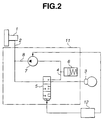
- a master brake cylinder 1 which is adapted to produce a hydraulic pressure when a driver which is not shown in the drawing depresses a brake pedal.
- the master cylinder 1 is connected to a wheel cylinder 3 through a hydraulic brake circuit 2.
- the brake circuit 2 incorporates therein a selector valve 5 which is changed over among a pressure increasing (boost-up) condition in which the upstream side (the master cylinder 1 side) of the brake circuit 2 is communicated with the downstream side (the wheel cylinder side) of the hydraulic circuit 2, a pressure decreasing (or reducing) condition in which brake fluid is relieved from the wheel cylinder into a drain circuit 4, and a pressure holding condition in which the brake circuit 2 is shut-off so as to hold a brake hydraulic pressure in the wheel cylinder 3.
- the hydraulic pressure in the wheel cylinder 2 can be optionally controlled by changing over the selector valve 5.
- drain circuit 4 is incorporated therein with a reservoir 6 for reserving therein brake fluid.
- a flowing (or circulating) circuit 8 is provided, connecting the reservoir 6 with the brake circuit 2 at a position upstream of the selector valve 5, and a pump 7 for feeding the brake fluid reserved in the reservoir 6 into the brake circuit 2 is provided in the flowing circuit 8.
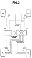
- An arrangement in a zone surrounded by a one-dot chain line in Fig. 2, corresponds to an integral brake unit 11. It is noted that although the arrangement having only one wheel is shown in Fig. 1, the entire arrangement is, as shown in Fig. 3, such that the brake unit 11 can control brake pressures in wheel cylinders 3 (which is not shown in Fig. 3) for four wheels FR, FL, RR, RL, respectively.
- a vehicle in which the present embodiment is applied is a rear wheel drive vehicle in which the rear wheels RR, RL are drive wheels.
- control unit 12 which is connected with four wheel speed sensors 13, as input means, for detecting rotational speeds of the wheels FR, FL, RR and RL.
- the brake control in this embodiment is adapted to carry out the so-called ABS control for controlling brake hydraulic pressure for each wheel in order to prevent the wheels from being locked upon braking.
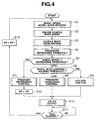
- Fig. 4 shows a flow-chart for the ABS control.
- the present brake control is carried out with a 10 msec cycle period.
- a sensor frequency is obtained from a number ND of sensor pulses and a period TD from each wheel speed sensor 13, which are generated in every 10 msec. cycle period, and then a wheel speed Vw and a wheel acceleration ⁇ Vw are calculated for each wheel.
- FR, FL, RR or RL is attached to the rear side of the reference mark Vw, it denotes a wheel speed of a particular one of the wheels FR, FL, RR, RL.
- step S2 a pseudo vehicle body speed Vi is calculated.
- This step S2 corresponds to a pseudo vehicle speed producing means. The calculation of the pseudo vehicle speed will be detailed later.
- a vehicle body deceleration ⁇ V is calculated from a rate of change of the pseudo vehicle speed Vi.
- a computation is carried out for obtaining a pressure decreasing (or reducing) threshold value ⁇ 1.
- the pressure reduction is carried when the wheel speed Vw becomes lower than this threshold value ⁇ 1.
- step S5 whether the wheel speed Vw is lower than the pressure reducing threshold value ⁇ 1 or not is determined. If it is lower than the pressure reducing threshold value ⁇ 1, control is transferred to step S7, at which the selector valve 5 is switched into the pressure reducing condition so as to carry out pressure reducing control for reducing the pressure in the wheel cylinder. Then, next at step S12, a timer AS for delivering an On-ABS control signal which indicates that the ABS control is in operation, is set at 150, for example. It is noted that in this pressure reducing control, the control signal is actually delivered to the selector valve 5 in a valve output process at step S10.
- step S5 determines whether the wheel acceleration ⁇ Vw is equal to or smaller than a preset holding threshold value or not. If the wheel acceleration ⁇ Vw is greater than the holding threshold value, it is estimated that the vehicle speed is recovered, and accordingly, at step S8, the pressure increase (boost-up) control is carried out (the selector valve 5 is changed over into the boost-up condition). Meanwhile, if the wheel acceleration ⁇ Vw is not greater than the holding threshold value, control is transferred to step 9, and the holding control (the selector valve 5 is turned into the holding condition) is carried out. An output operation to the selector valve 5 in either the boost-up control at step 8 or the holding control at step 9 is performed at step 10.
- step 11 whether 10 msec. elapses or not is determined. If 10 msec. has elapsed, control is transferred to step S13, at which the count of the timer AS for the On-ABS control signal is decremented (or decreased by one).
- the program section of step 101 to step 108 corresponds to an abnormal wheel determining means.
- step 109 shown in Fig. 6 it is determined whether the maximum wheel speed maxVw is greater than the pseudo vehicle speed Vi by a value exceeding a preset abnormality determining speed difference x, or not. If the answer is YES, that is, maxVw > Vi + x, the control unit 12 increments (or increase by one) on the count of the counter TCNT at step 110. If the answer of step 109 is NO, that is maxVw ⁇ Vi + x, the counter TCNT is cleared at step 111. Thus, steps 109 ⁇ S111 are designed to measure how long the abnormal condition, that is, maxVw > Vi + x, is continued, by counting with the counter TCNT.
- step 112 whether the count on the counter TCNT exceeds a preset abnormal determining time Y or not is determined. If the count is greater than Y (TCNT > Y), , that is, if the abnormal condition of the sensor continues for a time exceeding the abnormal determining time Y, control is transferred to step 113, the value of the abnormal wheel flag VMAX_AB is set to an abnormality concluding signal SVW_AB.
- the program section of steps 109 to 113 corresponds to an abnormality determining means.
- step 114 whether the abnormal concluding signal SVW_AB is produced or not is determined (SVW_AB ⁇ 0). If SVW_AB is not equal to zero (in the case that an abnormal wheel speed is present), the control unit 12 proceeds from step 114 to step 115, and sets the select wheel speed Vfs to a third values 3rdVw among the four wheel speeds. That is, the select wheel speed Vfs is set equal to the highest one among the three wheel speeds Vw except the wheel which is abnormal. If no abnormality concluding signal SVW_AB is produced, the control unit 12 proceeds to step 116, as a normal course, and sets the select wheel speed Vfs to the maximum (or highest) value maxVw among the four wheel speeds.
- step 117 shown in Fig. 7 whether or not the abnormality concluding signal SVW_AB was not produced at the previous control timing but it is produced at the current control timing, is determined.
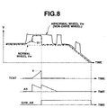
- Fig. 8 shows such a condition that a wheel speed Vw of the non-drive (driven) wheel becomes high due to imposed noise during braking from a constant speed running condition.
- the select wheel speed VFs is obtained from the highest one Vw among the wheel speeds of the four wheels through the steps 114 to 116, that is, it is obtained from the wheel speed Vw of an abnormal wheel until the count value on the counter TCNT exceeds the abnormality determining time through the steps 109 to 110.
- the pseudo vehicle body speed Vi is once increased following the wheel speed of the abnormal wheel.
- the wheel speeds Vw of the normal wheels are decreased to be smaller than the pseudo vehicle speed Vi by a large degree, and as a result, the pressure reducing control is executed for the normal wheels so as to produce the On-ABS control signal AS. It is noted that the driver does not carry out braking at this time, and accordingly, since the pressure in the wheel cylinders is still maintained to be the atmospheric pressure, and accordingly, the running condition will not vary.
- the abnormality concluding signal SVW_AB is set to 1 or 2 by the flow through steps 112 to 113, and the select wheel speed Vfs is obtained from the third higher wheel speed Vw, that is, a wheel speed Vw which is highest among the normal wheels.
- the select wheel speed Vfs is obtained from the third higher wheel speed Vw, that is, a wheel speed Vw which is highest among the normal wheels.
- the pseudo vehicle body speed Vi is still obtained from the third wheel speed Vw, and as shown, even though the wheel speed Vw of the abnormal wheel is abruptly increased, no ABS control is carried out.
- the abnormality concluding signal SVW_AS is set to 3 or 4.
- the flow is through the steps 122, 123 and 125, and at the time when AS becomes equal to 0, the abnormality concluding signal SVW_AB becomes equal to zero.
- Fig. 9 shows such a case that the wheel speed Vw of a drive wheel is abruptly increased during ABS control.
- the execution of the ABS control is started, and as the pressure is reduced, the wheel speed Vw of the drive wheel is sharply increased after the delivery of the On-ABS control signals AS is initiated.
- the select wheel speed Vfs is obtained from the maximum value among the four wheels, and as a result, as shown, the pseudo vehicle speed Vi is increased.
- the abnormality concluding signal SVW_AB becomes 3 or 4 which indicates a drive wheel, and as a result, the steps 114 to 115 are carried out so that the select wheel speed Vfs is determined by the maximum wheel speed 3rdVw among the normal three wheels. Accordingly, the pseudo vehicle speed Vi is determined from the select wheel speed Vfs by the flow through the steps 117 to 118, and as a result, the pseudo vehicle body speed Vi is lowered to a level equal to the normal wheel speed Vw.
- the pseudo vehicle body speed is determined from the wheel speeds of the wheels excluding the abnormal wheel, and accordingly, a difference between the pseudo vehicle body speed Vi and the normal wheel speed Vw becomes smaller, thus no pressure reduction is made.
- the abnormality concluding signal SVW_AB is set to be zero at step 125.
- the drive wheel slip is ended, and accordingly, since the abnormality concluding signal SVW_AB becomes zero, at step 116, the pseudo vehicle body speed Vi can be normally obtained even though the process of obtaining the pseudo vehicle speed Vi from the four normal wheels is resumed.
- the abnormality concluding signal SVW_AB is held to be not zero. If, on the other hand, the abnormal wheel is one of the drive wheels, the abnormality concluding signal VSW_AB is changed over into zero as the On-ABS control signal SVW_AB becomes zero.
- the abnormality concluding signal VSW_AB is again set to zero when a predetermined value (150) is counted after the final pressure reduction is started.
- the pressure in the wheel cylinder 3 is reduced, and held and increased by using only one selector valve 5.
- the selector valve 5 shown in Fig. 2 it is optional to employ a normally open two-position inflow valve which can be changed over between two position, and which can open and close the brake circuit 2, and a normally closed two-position outflow valve which can open and close the drain circuit 4.
- the control system can enhance the control quality without causing erroneous determination due to a spin of a drive wheel, and erroneous control due to this erroneous determination.
- a brake control system includes sections as shown in Fig. 1.
- a brake unit 100b is a section for decreasing a brake hydraulic pressure in at least one of wheel cylinders 100a.
- Wheel speed sensors 100c are devices for detecting rotational speeds of the wheels.
- a pseudo vehicle body speed producing section 100d is a section for determining a pseudo vehicle body speed in accordance with outputs from the wheel speed sensors 100c.
- An ABS control section 100e is a section for carrying out the ABS control to decrease the brake hydraulic pressure according to the need with the brake unit 100b in accordance with a difference between the pseudo vehicle body speed and each of the wheel speeds so as to prevent wheel locking upon braking.
- An abnormality determining section 100f is a section for causing the pseudo vehicle speed producing means 100d to determine the pseudo vehicle body speed in accordance with outputs from those of the vehicle speed sensors which exclude the one for a wheel with which an abnormality occurs.
- the abnormality determining section 100f includes at least an abnormal wheel discriminating section 100g for determining whether the wheel that is determined as being abnormal is a drive wheel or a driven wheel.
- the abnormality determining section 100f is arranged to differentiate the term for resetting determination of an abnormality depending upon whether the abnormal wheel is a drive wheel or a driven wheel.
Landscapes
- Engineering & Computer Science (AREA)
- Transportation (AREA)
- Mechanical Engineering (AREA)
- Regulating Braking Force (AREA)
Abstract
Description
Claims (8)
- A brake control system comprising:a brake unit for reducing brake hydraulic pressures in wheel cylinders for braking wheels of a vehicle, independent from one another;wheel speed sensors for detecting wheels speeds of the wheels, respectively;pseudo vehicle body speed producing means for determining a pseudo vehicle body speed in accordance with outputs of the wheel speed sensors;ABS control means for carrying out ABS control to prevent wheel locking on braking by decreasing a brake hydraulic pressure with the brake unit in accordance with a difference between the pseudo vehicle body speed and each of the wheel speeds; andabnormality determining means for detecting an abnormality in the outputs of the wheel speed sensors, and for causing the pseudo vehicle body speed producing means to determine the pseudo vehicle body speed in accordance with the outputs from the wheel speed sensors, excepting the output of the wheel speed sensor if an abnormality is detected therein;the abnormality determining means comprising an abnormal wheel discriminating means for determining whether an abnormal wheel is a drive wheel or not, to differentiate conditions for resetting the determination of abnormality in dependence on whether the abnormal wheel is a drive wheel or a non-drive wheel.
- A brake control system as set forth in claim 1, wherein said abnormality determining means resets the determination of abnormality on completion of the ABS control if the abnormal wheel is a drive wheel.
- A brake control system as set forth in claim 1, wherein, if the abnormal wheel is a non-drive wheel, said abnormality determining means resets the determination of abnormality when first and second conditions are satisfied, the first condition being satisfied when the ABS control is completed, the second condition being satisfied when the pseudo vehicle body speed is equal to 0 Km/h.
- A brake control system as set forth in claim 1, wherein the ABS control means terminates the ABS control when an elapsed time from the execution of a final pressure reducing operation exceeds a predetermined time.
- A brake control system as set forth claim 1, wherein said pseudo vehicle speed producing means selects, as a select wheel speed, a highest wheel speed among the wheel speeds of the four wheels and determines the pseudo vehicle body speed in accordance with the select wheel speed when an abnormality is not detected, and said pseudo vehicle speed producing means selects, as the select wheel speed, a highest wheel speed among the wheel speeds of the wheels excluding the abnormal wheel which is a wheel determined as being abnormal and determines the pseudo vehicle body speed in accordance with the select wheel speed when an abnormality is detected.
- A brake control system as set forth in claim 1, wherein said abnormality determining means determines that there is an abnormality when one of the wheel speeds becomes greater than the pseudo vehicle body speed by an amount exceeding a predetermined value.
- A brake system for a vehicle, comprising: a brake unit for decreasing brake fluid pressures to wheel cylinders for wheels of the vehicle individually;wheel speed sensors for sensing wheel speeds of the wheels of the vehicle; and a controllercalculating a pseudo vehicle body speed in accordance with the wheel speeds,decreasing the bake fluid pressure for each wheel in accordance with a difference between the pseudo vehicle body speed and the wheel speed of that wheel to prevent wheel locking during deceleration,judging one of the sensed wheel speed to be an abnormal wheel speed if the one of the sensed wheel speeds satisfies a predetermined condition to discriminate an abnormality,calculating the pseudo vehicle body speed by excepting the abnormal wheel speed if one of the sensed wheel speeds is judged to be the abnormal wheel speed,determining whether the wheel whose speed is judged to be the abnormal wheel speed is a drive wheel or a non-drive wheel of the vehicle, andresetting the judgment of judging the abnormal wheel speed under a first condition if the wheel whose speed is judged to be the abnormal wheel speed is a drive wheel, and under a second condition if the wheel whose speed is judged to be the abnormal wheel speed is a non-drive wheel.
- A brake control process for a vehicle, comprising:judging one of sensed wheel speeds to be an abnormal wheel speed if the one of the sensed wheel speeds satisfies a predetermined condition to discriminate an abnormality,calculating the pseudo vehicle body speed by excepting the abnormal wheel speed if one of the sensed wheel speeds is judged to be the abnormal wheel speed,determining whether the wheel whose speed is judged to be the abnormal wheel speed is a drive wheel or a non-drive wheel of the vehicle, andresetting the judgment of judging the abnormal wheel speed under a first condition if the wheel whose speed is judged to be the abnormal wheel speed is a drive wheel, and under a second condition distinct from the first condition if the wheel whose speed is judged to be the abnormal wheel speed is a non-drive wheel.
Applications Claiming Priority (2)
| Application Number | Priority Date | Filing Date | Title |
|---|---|---|---|
| JP14521999 | 1999-05-25 | ||
| JP11145219A JP2000335393A (en) | 1999-05-25 | 1999-05-25 | Brake control device |
Publications (3)
| Publication Number | Publication Date |
|---|---|
| EP1055574A2 true EP1055574A2 (en) | 2000-11-29 |
| EP1055574A3 EP1055574A3 (en) | 2003-03-19 |
| EP1055574B1 EP1055574B1 (en) | 2005-12-14 |
Family
ID=15380126
Family Applications (1)
| Application Number | Title | Priority Date | Filing Date |
|---|---|---|---|
| EP00111180A Expired - Lifetime EP1055574B1 (en) | 1999-05-25 | 2000-05-24 | Brake control system |
Country Status (4)
| Country | Link |
|---|---|
| US (1) | US6382739B1 (en) |
| EP (1) | EP1055574B1 (en) |
| JP (1) | JP2000335393A (en) |
| DE (1) | DE60024712T2 (en) |
Cited By (1)
| Publication number | Priority date | Publication date | Assignee | Title |
|---|---|---|---|---|
| WO2009031017A3 (en) * | 2007-09-06 | 2009-06-18 | Toyota Motor Co Ltd | Vehicle control device and method of controlling vehicle |
Families Citing this family (7)
| Publication number | Priority date | Publication date | Assignee | Title |
|---|---|---|---|---|
| JP2004322843A (en) * | 2003-04-24 | 2004-11-18 | Advics:Kk | Vehicle braking device |
| JP4706235B2 (en) * | 2004-11-12 | 2011-06-22 | トヨタ自動車株式会社 | Wheel speed sensor abnormality detection device and automobile equipped with the same |
| JP5060219B2 (en) | 2007-09-06 | 2012-10-31 | トヨタ自動車株式会社 | Vehicle control device |
| WO2009141923A1 (en) * | 2008-05-23 | 2009-11-26 | ボッシュ株式会社 | Vehicle abs control device with internal parameter auto-calibration function |
| JP2010101899A (en) * | 2009-12-04 | 2010-05-06 | Advics Co Ltd | Vehicle speed computing device |
| KR101846678B1 (en) * | 2016-06-08 | 2018-04-06 | 현대자동차주식회사 | Lane keeping assist method for vehicle |
| KR20250010907A (en) * | 2023-07-13 | 2025-01-21 | 에이치엘만도 주식회사 | System and method for electronic stability control of vehicle |
Family Cites Families (11)
| Publication number | Priority date | Publication date | Assignee | Title |
|---|---|---|---|---|
| JPH0351376U (en) * | 1989-09-27 | 1991-05-20 | ||
| JPH0516788A (en) * | 1991-07-11 | 1993-01-26 | Sumitomo Electric Ind Ltd | Estimated vehicle speed detection device for vehicle |
| US5510707A (en) * | 1992-09-10 | 1996-04-23 | Eaton Corporation | Wheel speed sensor input circuit with sensor status detection employing a resistor biased compensator |
| WO1995003964A1 (en) * | 1993-07-30 | 1995-02-09 | Kelsey-Hayes Company | Reduced brake switch dependence control method and system for vehicle anti-lock brake system |
| DE19511162A1 (en) * | 1995-03-27 | 1996-10-02 | Bosch Gmbh Robert | Brake system for a motor vehicle |
| DE19511161A1 (en) * | 1995-03-27 | 1996-10-02 | Bosch Gmbh Robert | Brake system for a motor vehicle |
| US5757641A (en) * | 1995-07-03 | 1998-05-26 | General Electric Company | Triplex control system with sensor failure compensation |
| DE19622462B4 (en) * | 1996-06-05 | 2004-12-09 | Robert Bosch Gmbh | Fault detection method and device |
| JP3290359B2 (en) * | 1996-07-22 | 2002-06-10 | 三菱電機株式会社 | Anti-lock brake control device |
| JPH10147232A (en) * | 1996-11-18 | 1998-06-02 | Sumitomo Electric Ind Ltd | Anti-lock control device |
| DE19705619A1 (en) * | 1997-02-14 | 1998-08-20 | Bosch Gmbh Robert | Method and device for controlling the brake force distribution in a motor vehicle |
-
1999
- 1999-05-25 JP JP11145219A patent/JP2000335393A/en active Pending
-
2000
- 2000-05-24 DE DE60024712T patent/DE60024712T2/en not_active Expired - Fee Related
- 2000-05-24 EP EP00111180A patent/EP1055574B1/en not_active Expired - Lifetime
- 2000-05-25 US US09/577,666 patent/US6382739B1/en not_active Expired - Fee Related
Cited By (3)
| Publication number | Priority date | Publication date | Assignee | Title |
|---|---|---|---|---|
| WO2009031017A3 (en) * | 2007-09-06 | 2009-06-18 | Toyota Motor Co Ltd | Vehicle control device and method of controlling vehicle |
| US8510010B2 (en) | 2007-09-06 | 2013-08-13 | Toyota Jidosha Kabushiki Kaisha | Vehicle control device and method of controlling vehicle |
| CN101795920B (en) * | 2007-09-06 | 2013-11-06 | 丰田自动车株式会社 | Vehicle control device and method of controlling vehicle |
Also Published As
| Publication number | Publication date |
|---|---|
| DE60024712T2 (en) | 2006-07-13 |
| EP1055574B1 (en) | 2005-12-14 |
| DE60024712D1 (en) | 2006-01-19 |
| US6382739B1 (en) | 2002-05-07 |
| EP1055574A3 (en) | 2003-03-19 |
| JP2000335393A (en) | 2000-12-05 |
Similar Documents
| Publication | Publication Date | Title |
|---|---|---|
| US4566737A (en) | Antiskid control with wheel-speed difference compensation | |
| EP0270092B1 (en) | Wheel spin control apparatus | |
| GB2326007A (en) | Vehicle tyre pressure monitoring system | |
| EP1055574B1 (en) | Brake control system | |
| US20030028308A1 (en) | Anti-skid brake control | |
| JPH0986377A (en) | Hydraulic pressure control device | |
| JPH06320923A (en) | Tire pressure detection method | |
| JP3490308B2 (en) | Anti-skid control method for motorcycle | |
| EP1055575B1 (en) | Automotive brake control system | |
| JPH1148938A (en) | Anti-skid control device | |
| JP3486078B2 (en) | Anti-lock brake control device for vehicle | |
| US5150952A (en) | Anti-skid control system for an automotive vehicle | |
| JP3984419B2 (en) | Anti-skid control device | |
| JP3508210B2 (en) | Anti-skid control device | |
| US5803557A (en) | Anti-lock brake control system for vehicle | |
| JP3629889B2 (en) | Anti-lock brake control device | |
| JPH10332720A (en) | Abnormality detection device for rotation speed sensor | |
| JPH09249110A (en) | Vehicle control device | |
| JPH11334568A (en) | Step determining device for vehicle running road surface | |
| JPH1178845A (en) | Anti-skid control device | |
| JP3509395B2 (en) | Anti-lock brake control device for vehicles | |
| JP2670784B2 (en) | Anti-lock brake control device | |
| JPH07174787A (en) | Abnormality detector for acceleration sensor | |
| JPH068959Y2 (en) | Brake device for vehicle | |
| JP3473072B2 (en) | Anti-skid control device |
Legal Events
| Date | Code | Title | Description |
|---|---|---|---|
| PUAI | Public reference made under article 153(3) epc to a published international application that has entered the european phase |
Free format text: ORIGINAL CODE: 0009012 |
|
| 17P | Request for examination filed |
Effective date: 20000524 |
|
| AK | Designated contracting states |
Kind code of ref document: A2 Designated state(s): AT BE CH CY DE DK ES FI FR GB GR IE IT LI LU MC NL PT SE |
|
| AX | Request for extension of the european patent |
Free format text: AL;LT;LV;MK;RO;SI |
|
| PUAL | Search report despatched |
Free format text: ORIGINAL CODE: 0009013 |
|
| AK | Designated contracting states |
Kind code of ref document: A3 Designated state(s): AT BE CH CY DE DK ES FI FR GB GR IE IT LI LU MC NL PT SE Designated state(s): AT BE CH CY DE DK ES FI FR GB GR IE IT LI LU MC NL PT SE |
|
| AX | Request for extension of the european patent |
Extension state: AL LT LV MK RO SI |
|
| AKX | Designation fees paid |
Designated state(s): DE GB |
|
| 17Q | First examination report despatched |
Effective date: 20040105 |
|
| RAP1 | Party data changed (applicant data changed or rights of an application transferred) |
Owner name: NISSAN MOTOR COMPANY, LIMITED Owner name: HITACHI, LTD. |
|
| GRAP | Despatch of communication of intention to grant a patent |
Free format text: ORIGINAL CODE: EPIDOSNIGR1 |
|
| GRAS | Grant fee paid |
Free format text: ORIGINAL CODE: EPIDOSNIGR3 |
|
| GRAA | (expected) grant |
Free format text: ORIGINAL CODE: 0009210 |
|
| AK | Designated contracting states |
Kind code of ref document: B1 Designated state(s): DE GB |
|
| REG | Reference to a national code |
Ref country code: GB Ref legal event code: FG4D |
|
| REF | Corresponds to: |
Ref document number: 60024712 Country of ref document: DE Date of ref document: 20060119 Kind code of ref document: P |
|
| PG25 | Lapsed in a contracting state [announced via postgrant information from national office to epo] |
Ref country code: GB Free format text: LAPSE BECAUSE OF NON-PAYMENT OF DUE FEES Effective date: 20060524 |
|
| PLBE | No opposition filed within time limit |
Free format text: ORIGINAL CODE: 0009261 |
|
| STAA | Information on the status of an ep patent application or granted ep patent |
Free format text: STATUS: NO OPPOSITION FILED WITHIN TIME LIMIT |
|
| 26N | No opposition filed |
Effective date: 20060915 |
|
| PG25 | Lapsed in a contracting state [announced via postgrant information from national office to epo] |
Ref country code: DE Free format text: LAPSE BECAUSE OF NON-PAYMENT OF DUE FEES Effective date: 20061201 |
|
| GBPC | Gb: european patent ceased through non-payment of renewal fee |
Effective date: 20060524 |